Airport Beacon
A rotating beacon system that identifies the airport location from the air, typically producing alternating green and white flashes. Serves as the primary visual landmark for pilots to locate the airfield during night and low‑visibility operations, with a distinctive colour sequence that distinguishes land airports (green/white) from water airports (yellow/white) and heliports (green/yellow/white).
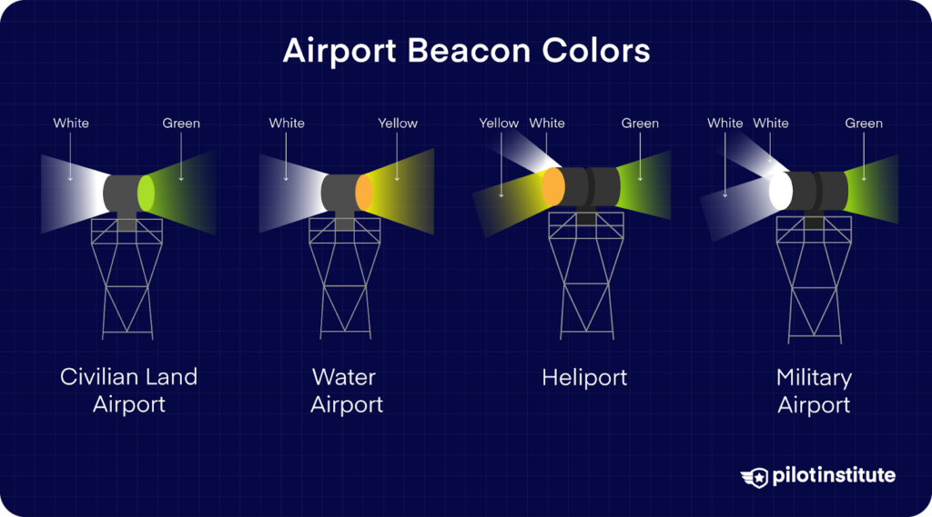
Image disclaimer: For identification and illustration only. It may show a product by another manufacturer and may not depict the exact item described; it is not a statement of any product’s quality, approval or performance. Third-party image and trademark rights belong to their owners. See full notice.
What Is It?
An Airport Beacon is a rotating aviation light system installed at airports to provide a visual identification signal to aircraft. The beacon produces alternating flashes of green and white light (for land airports) or yellow and white (for water airports), with a specific flash pattern (typically 24–30 flashes per minute). The rotating assembly ensures the light is visible from all directions. The beacon is mounted on a tall structure (control tower, hangar, or dedicated mast) and is visible from up to 30–40 nautical miles in clear conditions. It is one of the most critical visual aids for pilots approaching an airport at night, providing unambiguous identification of the airfield location.
Purpose & Function
The airport beacon exists to answer the most basic question a pilot faces on a night approach before any other lighting system becomes relevant: where is the airport, and is this the correct one? Visible from up to 30–40 nautical miles, it functions as a long-range locating signal rather than a precision guidance aid, giving the pilot a confirmed heading to fly toward long before the runway's own lighting system is close enough to be useful. The green/white versus yellow/white colour distinction exists specifically so a pilot can distinguish a land airport from a water airport at that same long range, preventing a costly misidentification before the pilot has committed to an approach, which is why the beacon's colour coding is treated as safety-critical rather than merely decorative.
Where Is It Used?
Installed at all civil and military airports that support night operations or low‑visibility approaches. Typically mounted on the control tower, a hangar roof, or a dedicated beacon tower at an elevated position to ensure maximum visibility. Used at land airports (green/white), water airports (yellow/white), and heliports (green/yellow/white). The beacon is often supplemented by secondary beacons at satellite terminals or remote aprons. It is one of the first lights pilots look for when locating an airfield.
Installation & Location
Fixtures are set out at the highest practical point on the control tower, hangar roof, or a dedicated beacon tower, chosen so the rotating beam has an unobstructed 360° sweep with no nearby structures, antennas, or terrain intruding on the horizon. The mounting platform is engineered to carry the beacon's static weight plus wind and vibration loading from the rotating assembly, with a service platform or hatch built in for lamp changes and gearbox maintenance. Power and control cabling runs from the beacon controller (housed in the tower or an adjacent equipment room) up to the beacon head, with lightning protection and surge suppression fitted given the beacon's exposed, elevated position. Where a dedicated mast is used rather than an existing building, the mast is sited clear of the runway's obstacle-limitation surfaces and sized to keep the beacon above surrounding rooftops and terrain within its designed visibility radius.
How Does It Work?
The airport beacon consists of a rotating optical assembly with two or more lamps (or LED arrays) that produce alternating colours. A motor rotates the assembly at a precise speed (typically 12–15 RPM) to produce the required flash rate. The light sources are high‑intensity halogen lamps or LED modules, with coloured filters (green and white) or dichroic lenses. The beacon is powered from the airport's electrical supply, with a backup generator or UPS to ensure continuous operation during power outages. Modern beacons use LED technology for longer life, lower power consumption, and instant‑on capability. The control system includes a photocell to turn the beacon on at dusk and off at dawn, or it may be manually controlled by ATC.
System Architecture & Control Logic
The beacon fixture is the visible output of a small closed system, not a standalone circuit — the actual decision-making happens one level up, in the Beacon Controller. A photocell, timer, or ATC command decides when the beacon should run (dusk-to-dawn, or a manual override for testing). That decision reaches the controller, which is the system's single control node: it sets the drive motor's rotation speed and independently sequences the lamp or LED colours and intensity. The Drive Motor turns the optical assembly at a fixed rate to produce the required flash cadence, while the lamp path handles colour and brightness — the two outputs run in parallel but are both timed off the same controller. If mains power fails, supply to the controller transfers automatically to a UPS or standby generator, so the flash cycle continues without an interruption a pilot would notice. Fault detection runs the opposite direction: motor current draw and lamp circuit health are both monitored by the controller, and any anomaly — a stalled motor, a failed lamp, loss of rotation — is reported upstream as a fault alarm to the ALCMS rather than corrected automatically at the beacon itself.
Command Source → Beacon Controller → Drive Motor + Lamp/LED Driver → Optical Assembly → Flash Output
What the Colour Pair Tells the Pilot
Green / White — this page's standard configuration, 24–30 flashes per minute.
Yellow / White — identifies a seaplane base rather than a land runway.
Green / Yellow / White — signals a helipad, not a fixed-wing airfield.
Because pilots often spot a beacon before anything else on the ground at night, the colour pair alone has to disambiguate the site — a green/white flash means "land here," while yellow or all-white pairings mean this beacon marks something else entirely.
Physical Construction
The beacon housing is a rotating drum or fixed-optic weatherproof enclosure, typically die-cast aluminium or corrosion-resistant alloy, mounted atop a fixed pedestal or tower structure to achieve the elevation needed for 360° visibility. Twin (or single) parabolic reflector-and-lens assemblies are mounted on a precision-balanced turntable driven by the beacon motor through a gear reduction stage, with slip rings or rotary couplings carrying power and control signals across the rotating joint. The enclosure is gasket-sealed and vented to prevent condensation while achieving an IP66/IP67 weather-resistant rating, with a toughened, UV-stabilised dome or window protecting the optics from wind-driven debris and precipitation. The base structure includes lightning protection bonding, a lockable access hatch for lamp and motor servicing, and cable entry glands sealed against moisture ingress. Stainless-steel and corrosion-resistant fasteners are used throughout, given the beacon's typically exposed, elevated mounting position.
Technical Parameters
| Parameter | Typical Value |
|---|---|
| Light Source | LED array or 200W–400W halogen / xenon |
| Colour Sequence | Green/White (land), Yellow/White (water), Green/Yellow/White (heliport) |
| Flash Rate | 24–30 flashes per minute (12–15 RPM rotation) |
| Intensity | Up to 50,000 cd (effective) |
| Beam Coverage | Omnidirectional (360° horizontal) |
| Mounting Height | Typically 15–50 m AGL (elevated for visibility) |
| Protection Class | IP66 / IP67, weather‑resistant |
| Power Supply | 230V AC with UPS / generator backup |
Electrical Requirements
| Requirement | Typical Value |
|---|---|
| Circuit Type | Dedicated mains-fed beacon circuit, independent of the airfield series lighting circuit |
| Supply Voltage | 230V AC ±10%, single-phase (drive motor and lamp/LED loads) |
| Backup Supply | UPS or standby generator with automatic changeover, maintaining continuous rotation and flash on mains loss |
| Control Input | Photocell/astronomical clock and Beacon Controller regulate colour sequence, flash rate, and day/night intensity |
| Cable Type | Heavy multicore power and control cable routed up the tower/mast to the elevated beacon head |
| Insulation Resistance | ≥ 50 MΩ (megger test, cable-to-ground) |
| Earthing/Grounding | Beacon housing, drive assembly, and tower structure bonded to the airfield earth grid, with lightning protection at the elevated mounting point |
| Fault Protection | Motor overload, lamp/LED failure, and loss-of-rotation-sync detection at the Beacon Controller |
Photometric Requirements
| Parameter | Typical Value |
|---|---|
| Colour Sequence | Alternating white and green (civil land airport) flashes per revolution |
| Rotation Speed | 12–15 RPM, producing 24–30 flashes per minute |
| Peak Beam Intensity | ≥ 2,000 cd per colour, per ICAO Annex 14 / FAA AC 150/5345-12 |
| Vertical Beam Spread | Narrow vertical beam (~2°–3°) for maximum range at the horizon |
| Horizontal Coverage | 360° visibility as the beam sweeps continuously with rotation |
| Chromaticity | White and green (or green/yellow/white for heliports) within ICAO Annex 14 colour boundaries |
| Day/Night Intensity Control | Photocell/astronomical clock-selected day and night intensity steps |
| Rotation Speed Tolerance | ± 1% of rated RPM to maintain a consistent flash rate |
| Test Method | Rotation speed and flash-rate verification at commissioning and semi-annual maintenance |
Applicable Standards
ICAO Annex 14
Airport beacon colour, intensity, and flash pattern requirements
FAA AC 150/5345-12
Specification for airport rotating beacons
IES LM-79 / LM-80
LED luminaire photometric/electrical testing and lumen maintenance (LED beacon performance)
Installation Requirements
Tower/Pedestal Structural Check
CivilConfirm the supporting tower or pedestal is rated for the beacon's weight, wind loading, and vibration before mounting, with the access hatch and cabling route accounted for in the design.
Turntable Levelling & Alignment
MechanicalSet the beacon base plumb and level on its mount so the rotating turntable tracks true, avoiding bearing wear or beam wobble from an out-of-level installation.
Lightning Protection Bonding
ElectricalBond the beacon housing and support structure to the site's lightning protection system, given the beacon's typically elevated, exposed mounting position.
Power & Standby Supply Termination
ElectricalTerminate the 230V AC supply and confirm the UPS/generator standby feed is wired and set to transfer automatically on mains failure before energisation.
Slip Ring / Rotary Coupling Wiring
ElectricalTerminate power and control wiring at the slip ring or rotary coupling per manufacturer procedure, checking free rotation is not fouled by cable slack or routing.
Cable Entry & Enclosure Sealing
MechanicalSeal cable entry glands and confirm the enclosure gasket and dome/window seat correctly to achieve the rated IP66/IP67 protection before closing the access hatch.
Colour Pair Configuration
ConfigurationConfirm the correct colour sequence (green/white, yellow/white, or green/yellow/white) is fitted for the site type before commissioning, since this identifies the facility to arriving pilots.
Pre-Energisation Sign-off
DocumentationRecord mounting height, bonding, cable termination, and colour pair configuration as-built before the tower or pedestal access is closed out.
Testing & Commissioning
Insulation Resistance Test
Pre-EnergisationMegger-test the beacon's supply cable and motor windings before energisation, confirming insulation resistance clears the acceptable minimum.
Rotation Direction & Free-Spin Check
Pre-EnergisationManually rotate the turntable to confirm free, unobstructed movement and correct rotational direction before the drive motor is powered.
Photocell / Timer Threshold Verification
EnergisationConfirm the beacon switches on and off at the correct ambient light threshold, simulating dusk and dawn conditions or applying a manual override.
Colour Sequence Verification
EnergisationConfirm the correct alternating colour pair (green/white for land, yellow/white for water, or the applicable heliport pair) as the turntable completes a full sweep.
Rotation Speed & Flash Rate Verification
EnergisationTime the turntable rotation to confirm 12–15 RPM, producing the required 24–30 flashes per minute at the design colour sequence.
Photometric Intensity Test
Final AcceptanceMeasure beam intensity and colour with a calibrated photometer against ICAO/FAA thresholds prior to operational handover.
Backup Power / UPS Transfer Test
Final AcceptanceSimulate a mains failure and confirm the beacon transfers to backup power without an extended outage or loss of rotation.
Mounting & 360° Sightline Clearance Check
Final AcceptanceConfirm the beacon's elevated position gives an unobstructed 360° sweep with no nearby structures, antennas, or terrain intruding on the beam.
Documentation & As-Built Sign-off
Final AcceptanceRecord insulation, rotation speed, colour sequence, and photometric readings alongside as-built position in the commissioning dossier for handover.
Inspection & Maintenance
Photometric Intensity Check
AnnualVerify effective intensity for both colours in the sequence against ICAO / FAA thresholds using a calibrated photometer; degraded output usually points to filter fade or lamp aging.
Rotation Speed Verification
Semi-annualConfirm the beacon rotates at the correct RPM to deliver the required 24-30 flashes per minute, since drive wear can slow rotation over time.
Motor Bearing Inspection
AnnualCheck for noise, vibration, or drag in the rotating mechanism, and lubricate or replace bearings on schedule (typically every 5-7 years) before they seize.
Colour Filter Inspection
AnnualCheck green and yellow filters for UV fade or discoloration and replace on schedule to keep the colour sequence within the required chromaticity boundary.
Lens Seal & Desiccant Check
Semi-annualInspect seals around the rotating lens for degradation and refresh desiccant packs to prevent moisture ingress and internal fogging of the optics.
Power Supply & Backup Test
AnnualTest UPS and generator backup transfer to confirm the beacon stays operational through a mains power loss, since continuous operation is safety-critical after dark.
Housing & Mounting Inspection
AnnualCheck the tower or rooftop mounting structure, weatherproofing, and cable entries for corrosion or wear given the beacon's typically elevated exposure.
Common Field Issues
Motor Bearing Wear
The rotating mechanism is subject to continuous wear. Bearing failure can cause erratic rotation, reduced flash rate, or complete stoppage. Regular lubrication and replacement of bearings (every 5–7 years) is essential.
Colour Filter Degradation
Green and yellow filters fade over time due to UV exposure and heat, altering the colour sequence. Annual photometric inspection and filter replacement is required to maintain the correct colour identification.
Moisture Ingress in Lens Assembly
Seals around the rotating lens can fail, allowing moisture to enter and fog the optics. Regular seal inspection and replacement, along with desiccant maintenance, is critical for optical clarity.
Troubleshooting Guide
Beacon Not Rotating
Erratic or Inconsistent Rotation Speed
One Colour Beam Weak, Missing, or Wrong Hue
Beacon Completely Dark
Fogged, Hazy, or Discoloured Optics
Failure Modes & Root Causes
Drive Motor / Bearing Seizure
Beacon Controller Fault
Colour Filter / Lens Degradation
Weatherseal / Gasket Failure
Lamp / LED Source End-of-Life
Safety & Operational Notes
Elevated Access
Fall ProtectionThe beacon is mounted on a control tower, hangar roof, or dedicated mast; use fall-arrest equipment and follow the facility's rooftop or tower-access permit before approaching the unit.
Electrical Isolation
Electrical SafetyDe-energise and lock out the beacon supply at the controller before opening the lens housing or drive assembly, and verify zero energy before touching motor or lamp connections.
Rotating Assembly Pinch Points
MechanicalKeep hands and tools clear of the turntable and drive train until it is confirmed stationary and electrically isolated; never attempt to manually check rotation speed on an energised unit.
Direct Beam Viewing
Personnel SafetyAvoid looking directly into the beam at close range when the beacon is under test with the lens installed; the focused output is intense enough to cause temporary glare or discomfort.
ATC / Airfield Coordination
OperationalNotify ATC and raise a NOTAM before any planned outage, since the airport beacon is a primary night-identification aid and its loss affects arriving traffic beyond the immediate airfield.
PPE
Personnel SafetyWear cut-resistant gloves when handling the colour filter/lens segments and insulated tools for electrical work, and use fall-protection PPE appropriate to the mounting height.
Restore to Compliant State
ComplianceConfirm correct flash rate, colour sequence, and photometric output before closing out the work and cancelling the associated NOTAM.
Engineering & Expert Notes
Check the Green Beam First, Not the White
InspectionThe dyed green filter is almost always the first colour to visibly fade under UV, so a periodic chromaticity check should target the green segment before the white beam even shows a symptom. Waiting for a pilot report of a "weak green" means the filter has already drifted well past the point a photometric check would have caught it.
Time the Rotation, Don't Just Watch It
DiagnosticsA beacon can look like it's rotating normally to the eye while running measurably off the rated RPM, which throws the flash rate out of the 24–30 flashes-per-minute window without ever stopping. Clock actual rotations against a stopwatch during routine inspection rather than relying on a visual "looks fine" check.
Desiccant Condition Predicts the Next Fogging Event
ReliabilityLens fogging on a rotating beacon is rarely the seal failing outright; it's usually exhausted desiccant that stopped absorbing the small amount of moisture a "good" seal still lets through over years. Track desiccant colour/saturation as a leading indicator at every inspection, not just as a line item after fogging is already reported.
Re-Survey the Sweep After Any Nearby Construction
SitingA beacon sited correctly at commissioning can lose part of its 360° sweep years later if a crane, new hangar, or antenna goes up nearby. Re-verify unobstructed line-of-sight around the tower whenever new structures appear on the airfield, rather than assuming the original siting survey still holds.
Rule Out the Controller Before Replacing the Motor
TroubleshootingErratic rotation speed is diagnosed as a motor/bearing problem by default, but a controller with a drifting speed-regulation circuit produces the identical symptom on a mechanically healthy motor. Confirm the controller's output is a stable, correctly regulated supply before committing to a motor or bearing replacement.
Surge Protection Earns Its Keep on This Fixture
ElectricalBecause the beacon sits at the highest point on the tower or mast, it takes the brunt of any lightning-induced transient reaching the site. Verify surge suppression at both the controller and the beacon head at every major service, since a degraded arrester often shows no symptom until the next strike takes the controller with it.
Frequently Asked Questions
Short answers about airport beacons: colour sequence, flash rate, visibility, power, standards, maintenance and common faults.
Q1What is an airport beacon?
An airport beacon is a rotating aviation light installed at an airport to give pilots a visual identification signal. It sweeps alternating flashes through 360° so the airfield can be located from a long distance at night, well before the runway lighting is close enough to be useful.
Q2What colours does an airport beacon show?
A civil land airport beacon alternates green and white flashes. A water airport beacon alternates yellow and white, and a heliport beacon uses a green, yellow and white sequence.
Q3What is the flash rate of an airport beacon?
The beacon produces 24–30 flashes per minute, achieved by rotating the optical assembly at 12–15 RPM with two flashes per revolution. Rotation speed is typically held within ±1% so the flash rate stays consistent.
Q4How far can an airport beacon be seen?
In clear conditions an airport beacon is visible from about 30–40 nautical miles. Effective intensity can reach up to 50,000 cd, with a narrow vertical beam of roughly 2°–3° to maximise range at the horizon.
Q5Where is an airport beacon installed?
It is mounted at the highest practical point, such as the control tower, a hangar roof or a dedicated beacon tower, typically 15–50 m above ground level. The site must give an unobstructed 360° sweep, with no structures, antennas or terrain intruding on the horizon.
Q6What power supply does an airport beacon use?
It runs on a dedicated mains-fed circuit, typically 230 V AC single-phase, independent of the airfield series lighting circuit. A UPS or standby generator with automatic changeover keeps rotation and flashing going during a mains failure, and a photocell or astronomical clock with the Beacon Controller sets day and night intensity.
Q7Which standards apply to airport beacons?
The main references are ICAO Annex 14 (colour, intensity and flash pattern), FAA AC 150/5345-12 (specification for airport rotating beacons) and IES LM-79 / LM-80 for LED photometric testing and lumen maintenance. Always verify the current edition and your aerodrome's approved requirements.
Q8What are the photometric requirements for an airport beacon?
Peak beam intensity is typically at least 2,000 cd per colour, per ICAO Annex 14 and FAA AC 150/5345-12. Chromaticity must stay within the ICAO Annex 14 boundaries for white and green (or yellow), and rotation speed tolerance is about ±1% of rated RPM.
Q9How often should an airport beacon be inspected and maintained?
Typical intervals are annual for photometric intensity, motor bearing and colour filter checks, and semi-annual for rotation speed verification and lens seal and desiccant checks. Bearings are typically replaced every 5–7 years. Your airport's approved maintenance programme takes precedence.
Q10Why is an airport beacon not rotating?
The usual causes are seized or worn drive motor bearings, a failed drive motor, or an open circuit in the motor supply from the beacon controller. Check for supply voltage at the motor terminals, turn the head by hand with power off to feel for binding, and test winding continuity and insulation resistance. Confirm the correct RPM before returning the beacon to service.
Related Components
Go Beyond the Component. Understand the Complete AGL System.
You have explored the component. Now understand how it works within the complete Airfield Ground Lighting system.
Learn AGL from fundamentals to design, installation, testing, photometry, commissioning, maintenance and troubleshooting through structured technical training at Precision AGL Academy.
Build practical knowledge. Understand the circuit. Read the standards. Troubleshoot with confidence.
Your next step in AGL starts here.
Need expert guidance on airport beacon selection or installation?
Precision AGL Academy provides advice on colour coding, rotation speed, and compliance for airport identification beacons.
Follow the Academy
Important Notice, Disclaimer & Limitation of Liability
Please read before relying on any content on this page.
- Purpose and intended users. This page on Airport Beacon is an independent educational and informational reference for competent, suitably trained and authorised airfield ground lighting (AGL) and aerodrome electrical personnel. It is not professional engineering, legal or regulatory advice, and using it does not create any professional or client relationship.
- Safety. Work on series circuits, constant current regulators (CCRs), isolating transformers, cables, connectors and lighting equipment can be fatal. Always apply the aerodrome’s permit-to-work and isolation/LOTO procedures, prove dead, use correctly rated instruments and PPE, and follow the manufacturer’s instructions. Nothing here authorises work on live equipment or the bypassing of any safety device or interlock.
- Aviation operations. Nothing here authorises installation, modification, energisation, adjustment, return to service, a change of operating category (CAT I/II/III), a NOTAM or any aerodrome certification or approval decision. These rest with the aerodrome operator, the air navigation service provider and the competent regulator.
- Specifications, ratings and typical values. Descriptions, parameters, ratings, dimensions, photometric values, wattages, service lives, maintenance tasks and intervals, failure modes, certifications (for example CE, FCC, UL or IEC marks) and part or type designations are general, typical and indicative. They may not match any particular product, make, model or version, and they are not a datasheet, design, specification, selection, sizing, procurement or acceptance criterion. The manufacturer’s current documents, the approved design and the project specification prevail.
- Standards and regulations. References to ICAO, FAA, IEC, IEEE, ISO, BIS, DGCA and other standards are paraphrased summaries for orientation only. They may be incomplete or out of date, and standards are revised from time to time. Consult the current official editions. Following this content does not guarantee compliance with any law, standard or regulatory approval, and the regulator’s requirements always prevail.
- No warranty. Content is provided “as is” and “as available”, without warranty of any kind, express or implied, including accuracy, completeness, currency or fitness for a particular purpose. Real installations differ in design, equipment make and model, age and condition.
- Limitation of liability. To the fullest extent permitted by applicable law, Precision AGL Academy, Precision AGL Solutions and their owners, authors and contributors are not liable for any injury, death, loss, damage, downtime, penalty or regulatory consequence, whether direct or indirect, arising from the use of, reliance on, or inability to use this content. Nothing in this notice excludes or limits any liability that cannot lawfully be excluded or limited.
- Independence, brands and no endorsement. This is an independent publication. It is not affiliated with, sponsored by or endorsed by ICAO, the FAA, the IEC, DGCA, AAI, any airport, regulator, supplier or equipment manufacturer. Third-party names, product designations, standard designations and trademarks (including Megger®, Siemens, Eaton, Crouse-Hinds, ADB SAFEGATE, Fluke, ABB and Honeywell) belong to their respective owners and are used only for identification and description. Mention of a brand, product or supplier is not a recommendation, and we do not sell, supply or quote for any component described.
- Images and third-party content. Images and illustrations are shown to help identify the type of component. They may show products of various manufacturers, may not depict the exact item described, and are not a statement about any product’s quality, approval or performance. Copyright and trademarks in third-party images, logos and photographs belong to their respective owners and are not claimed as ours. If you are a rights holder and want an image removed, replaced or credited, email precisionaglsolutions@gmail.com with the page address and we will act promptly.
- Training and services. Mentions of training, courses, consultation, advice, selection, installation, calibration or other support, including the “Learn…Certify” pathway, describe learning stages and are not an offer, quotation, tender or promise of any result. Contacting us or our replying creates no engagement or duty of care; an engagement exists only under a written agreement. We are not a regulator or certification body, and completing any course or reading this content is not a certification, accreditation or authorisation to work on any aerodrome.
- Copyright, privacy and corrections. © 2026 Precision AGL Academy. All rights reserved. Text, structure, compilations and diagrams may be viewed for personal reference and internal training only; any other copying, republication or commercial use needs our written permission. If you email, telephone or message us, we use your details only to respond and handle your matter, in line with applicable Indian law including the Digital Personal Data Protection Act, 2023; please do not send confidential or security-sensitive information. To display this page your browser requests fonts, icons and images from third-party servers, which receive your IP address and browser details under their own policies. Content is reviewed periodically with no obligation to update. To report an error, safety concern or rights issue, write to precisionaglsolutions@gmail.com.