ALSF‑2
A high‑intensity approach lighting system for Category II and III precision approaches, featuring a full 731m (2,400 ft) – or 914m (3,000 ft) – configuration of barrettes, sequenced flashing lights, and additional red side‑row bars. The ALSF‑2 provides exceptional visual guidance for low‑visibility operations down to 200m RVR, enabling safe landings in the most demanding weather conditions.
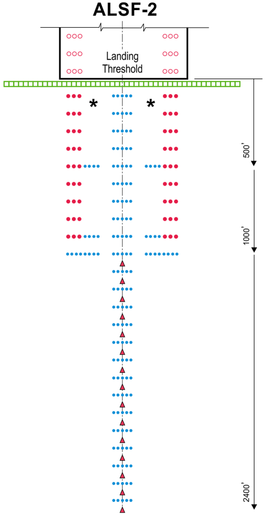
Image disclaimer: For identification and illustration only. It may show a product by another manufacturer and may not depict the exact item described; it is not a statement of any product’s quality, approval or performance. Third-party image and trademark rights belong to their owners. See full notice.
What Is It?
The ALSF‑2 (Approach Lighting System with Sequenced Flashing lights – Category II/III) is a high‑intensity precision approach lighting system designed for the most demanding low‑visibility operations. It extends 731 metres (2,400 ft) – or 914 metres (3,000 ft) on shallow-slope sites – from the runway threshold and includes all the features of the ALSF‑1 plus additional red side‑row bars and enhanced intensity. The system provides pilots with both horizontal and vertical guidance during CAT II and CAT III approaches, with decision heights as low as 100ft (CAT II) and 50ft or less (CAT III), and RVR down to 200m or lower. The ALSF‑2 is essential for airports that operate in regions with frequent fog, rain, or snow.
Purpose & Function
ALSF-2 exists to extend the ALSF-1 foundation specifically to the point where CAT II and CAT III minimums become achievable, adding red side-row bars and enhanced intensity precisely because the lower decision heights and shorter visual segments of those categories demand more visual information delivered with greater reliability than CAT I alone requires. The red side-row bars in particular give the pilot a distinct visual marker of entering the final, most critical approach segment, an added layer of positional awareness that CAT I operations don't need but that CAT II/III's tighter margins make valuable. Its purpose is to be the standard high-intensity system wherever an airport must support routine operations in the fog, rain, or snow-prone conditions that make CAT II/III capability operationally necessary rather than optional.
Where Is It Used?
ALSF‑2 systems are installed at airports that support Category II and III precision approaches. They are typically used on:
- Precision approach runways with CAT II/III capability (100ft DH or lower, 200m RVR or lower)
- Major international hub airports requiring reliable low‑visibility operations
- Airports in regions with adverse weather (fog, heavy rain, snow)
- Military airbases supporting all‑weather operations
- Runways with high traffic volume where operational continuity is critical
Installation & Location
Fixtures are set out along the extended runway centreline for the full 900 m length, on frangible stands graded to the approach slope; structures crossing roads, water, or depressions are elevated on piers or catwalks to keep the array on a consistent plane. The red side-row bars and threshold-adjacent lights in the final 300 m are tied into the runway's own lighting so the transition from approach to runway reads as one continuous system. Because ALSF‑2 supports CAT II/III operations, stands and cabling are typically arranged on independently fed circuits so a single fault cannot extinguish the full array, with cable runs in duct back to redundant constant current regulators. Setting-out follows the extended centreline and threshold survey to the same tolerance as the runway lighting it feeds into.
How Does It Work?
The ALSF‑2 system builds on the ALSF‑1 with enhanced features for lower visibility:
- Barrettes: A series of light bars (typically 3 to 5 lights per bar) positioned at 30m (100 ft) intervals along the full 731m/914m approach path. These provide distance and lateral guidance.
- Sequenced Flashing Lights (SFL): A row of lights that flash in sequence from the outer end toward the threshold, creating a "rolling" effect that indicates the approach direction and helps pilots maintain the correct glide slope. The SFL in ALSF‑2 has higher intensity and faster flash rate for better visibility in fog.
- Red Side‑Row Bars: Additional red lights installed on both sides of the approach path in the final 300m segment. These provide a visual warning if the aircraft deviates laterally from the centreline and help define the approach corridor.
- Centreline Barrette: A short row of lights on the approach centreline, providing precise lateral guidance and helping pilots align with the runway.
- Decision Bar: A row of lights at the decision height point, providing a visual reference for the pilot's go/no‑go decision.
- Intensity Control: The entire system is controlled by CCRs with multiple intensity steps (typically 5 steps), with higher intensities used during low‑visibility conditions. The system also includes automatic dimming based on RVR data.
System Architecture & Control Logic
As with ALSF‑1, the ALSF‑2 array runs two electrically independent control paths. Steady-burning elements — barrettes, red side-row bars, centreline barrette, and the decision bar — sit on a constant current series circuit: the ALCMS selects the intensity step based on RVR, ATC instruction, or automatic visibility-linked logic, the CCR regulates the whole loop to a single fixed current, and every steady fixture on that loop burns at the same brightness via its own isolating transformer. The sequenced flashing lights are driven separately by a flasher/sequencer controller that discharges through each SFL lamp in strict outer-to-threshold order; in ALSF‑2 this sequencer is tuned for a higher flash rate and higher peak intensity than ALSF‑1 for better fog penetration. The ALCMS commands both subsystems in step together — raising RVR-linked brightness raises both the steady loop's current and the SFL's intensity tier — but a fault in one subsystem does not propagate to the other, and each is fault-monitored independently by its own controller.
ALCMS commands both the steady CCR loop and the high-intensity SFL sequencer in step
Approach Path Sequence
Faster, higher-intensity flash sequence rolls toward the runway — enhanced over ALSF‑1 for CAT II/III visibility
Physical Construction
Barrette stands are frangible structures carrying multiple lamp housings on a rigid bar, graded in height along the stand run to keep the array on the approach slope; die-cast aluminium housings behind toughened, gasket-sealed lenses achieve an IP67/IP68 rating on each lamp. The sequenced flashing heads use higher-output xenon strobe tubes and trigger electronics than a CAT I system, housed in weatherproof domes with correspondingly larger capacitor banks at the base of each stand to sustain the faster, higher-intensity sequence. Red side-row bar fixtures in the final 300 m and the threshold-adjacent lights share the same die-cast, gasket-sealed construction as the runway's own edge and threshold lights, so the approach hardware transitions seamlessly into the runway lighting system. Where the approach crosses roads, water, or depressions, stands are raised on piers or catwalks engineered to keep the array coplanar, and because ALSF-2 supports CAT II/III operations, circuits are built with independent cabling and redundant isolating transformers so a single fault cannot take down the full array. Stainless-steel fasteners and corrosion-resistant finishes are used throughout.
Technical Parameters
| Parameter | Typical Value |
|---|---|
| System Type | ALSF‑2 (CAT II/III precision approach) |
| Light Source | LED array or halogen (100W – 200W, high‑intensity) |
| Colour | White (steady and flashing), Red (side‑row bars) |
| Configuration Length | 731 metres / 2,400 ft (standard) – 914 metres / 3,000 ft (extended, shallow-slope sites) |
| Barrette Spacing | 30m (100 ft) intervals along full length |
| Sequenced Flashing Lights | High‑intensity, fast sequence (flashing toward threshold) |
| Side‑Row Bars | Red lights on both sides of the final 300m segment |
| Decision Bar | Present at decision height point |
| Intensity Steps | 5‑step (2.8A – 6.6A) CCR controlled, with automatic dimming |
| Beam Pattern | Uni‑directional towards approach, narrow beam for high intensity |
| Mounting Type | Elevated or flush‑mounted (inset) |
| Isolating Transformer | 100W – 200W (6.6A series circuit) |
| Protection Class | IP67 / IP68 (submersible) |
| Support | CAT II (100ft DH, 300m RVR) / CAT III (50ft or less DH, 200m or less RVR) |
Electrical Requirements
| Requirement | Typical Value |
|---|---|
| Circuit Type | Independent series circuits (CCR fed) for centreline barrettes, red side-row bars, and SFL/strobe array |
| Rated Series Current | 6.6A per circuit (5-step: 2.8A / 3.4A / 4.1A / 5.2A / 6.6A) |
| Isolation | Dedicated isolating transformer (100W – 200W) per fixture; SFL heads fed from dedicated capacitor-discharge units |
| Transformer Secondary | Matched to fixture wattage; sized to series circuit rating |
| SFL Power Supply | High-output capacitor-discharge trigger units driving xenon strobes, synchronised by a flasher controller at the faster CAT II/III sequence rate |
| Cable Type | L-824 single-conductor, direct-burial rated, 5kV per circuit; shielded trigger cable for SFL synchronisation |
| Connector | L-823 primary connector, submersible-rated splice |
| Insulation Resistance | ≥ 50 MΩ (megger test, cable-to-ground) |
| Earthing/Grounding | Fixture body, stands, and base cans bonded to airfield earth grid |
| Fault Protection | CCR-level ground fault and open-circuit detection per circuit sector; SFL controller health monitoring |
| Redundancy | Independent cabling and duplicate isolating transformers per circuit sector, so a single fault cannot take down the full array |
| Power Source | CCR output per circuit, regulated per ICAO/FAA CAT II/III intensity step schedule |
Photometric Requirements
| Parameter | Typical Value |
|---|---|
| Centreline Barrette Intensity | 10,000 – 20,000 cd (white), 5-step: 100% / 30% / 10% / 3% / 1% |
| Red Side-Row Bar Intensity | ≥ 2,000 cd (red) from 1,000 ft to touchdown-side row |
| SFL Peak Effective Intensity | ≥ 20,000 effective cd (white xenon strobe), higher-output units toward CAT III end of the range |
| SFL Flash Rate | Faster sequence rate than ALSF-1, synchronised outward-to-threshold along the centreline |
| Vertical Beam Spread | Main beam 1°–12° above horizontal (peak ~2°–3°) |
| Horizontal Beam Spread | ± 4.5° either side of runway centreline extended, plus dedicated red side-row spread |
| Chromaticity | White (centreline/SFL) and red (side-row bars) within ICAO Annex 14 boundaries |
| Isocandela Distribution | Per ICAO Annex 14 Attachment A / FAA AC 150/5340-30 ALSF-2 figures |
| Test Method | Mobile photometric van/goniophotometer per circuit sector, plus SFL flash-timing verification against the CAT II/III sequencing schedule |
Applicable Standards
ICAO Annex 14
ALSF‑2 configuration, spacing, colour, and photometric requirements
FAA AC 150/5345-46
Specification for ALSF‑2 approach lighting components
IEC 61827
Electrical and photometric performance for AGL luminaires
FAA Engineering Brief #67
LED ALSF‑2 component performance requirements
Installation Requirements
Frangible Stand Footing & Slope Grading
CivilSet each stand footing along the full 900 m run to the design height so the array follows the approach slope, holding tolerance from the outer end through to the threshold.
Elevated Piers & Catwalks Over Obstacles
CivilInstall piled structures or catwalks wherever the approach crosses roads, water, or depressions, engineered to keep the array coplanar across the full length.
Duct & Redundant Cable Routes
ElectricalLay independently routed duct runs for the steady, high-intensity SFL, and red side-row bar circuits, keeping each on its own feeder so a single fault cannot extinguish the full array.
L-823 Connector Termination
ElectricalTerminate and seal primary connectors on every circuit per manufacturer procedure, keeping each splice fully submersible-rated before backfill.
Redundant Isolating Transformer Matching
ElectricalConfirm isolating transformer wattage and ratio match each circuit's rated current step, with steady, SFL, and side-row transformers kept on their independently fed loops.
Barrette, SFL & Side-Row Assembly
MechanicalFix lamp housings to barrette bars, mount SFL heads on their stands, and install red side-row bar fixtures in the final 300 m, torquing all frangible fittings to spec.
Setting-Out & Runway Transition
MechanicalTie stand positions to the extended centreline and threshold survey to the same tolerance as the runway lighting it feeds into, keeping the approach-to-runway transition continuous.
Pre-Energisation Sign-off
DocumentationRecord stand positions, redundant cable routes, connector seals, and torque values as-built for every circuit before backfill, since these are not inspectable once the site is closed.
Testing & Commissioning
Insulation Resistance (Megger) Test
Pre-EnergisationMegger-test the steady-burning circuit, the high-intensity SFL circuit, and the red side-row bar circuit separately before backfill, confirming each clears the acceptable minimum.
Loop Continuity & Resistance Test
Pre-EnergisationVerify series loop continuity and record total loop resistance for the full 731m/914m run, including the side-row bars and decision bar, before first energisation.
Primary/Secondary Voltage Verification
EnergisationWith the CCR energised, confirm secondary voltage at each barrette and side-row bar transformer matches the rated ratio at the commissioned current step.
Automatic RVR-Linked Dimming Verification
EnergisationSimulate a range of RVR inputs to the ALCMS and confirm the CCR automatically steps intensity up or down in line with CAT II/III visibility-linked control logic.
Sequenced Flashing & Decision Bar Response
EnergisationConfirm the high-intensity SFL sequence fires correctly toward the threshold and that the decision bar illuminates and aligns with the decision-height reference point.
Side-Row Bar & Barrette Alignment Verification
Final AcceptanceCheck elevation, azimuth, and colour segregation of every barrette and red side-row light against the design aiming diagram, correcting any deviation before sign-off.
Photometric Commissioning Test
Final AcceptanceMeasure beam intensity and colour of white and red elements with a calibrated photometer against ICAO/FAA CAT II/III commissioning tolerances.
Documentation & As-Built Sign-off
Final AcceptanceRecord insulation, continuity, voltage, dimming-response, and photometric readings alongside as-built positions in the commissioning dossier for handover.
Inspection & Maintenance
Photometric Intensity Check
AnnualVerify barrette, side-row bar, and centreline beam intensity against ICAO / FAA thresholds using a calibrated photometer across the full 731m/914m high-intensity configuration.
Barrette & Side-Row Lens Cleaning
QuarterlyClear dust, insect residue, and weathering film from barrette, side-row, and centreline lenses so beam output stays within spec at CAT II/III intensity levels.
Sequenced Flasher Timing Test
Semi-annualConfirm the high-intensity sequenced flashers fire in the correct rapid outer-to-threshold order, since a stuck or mistimed flasher undermines the approach cue at low visibility.
Decision Bar Function Check
Semi-annualVerify the decision bar at the decision height point illuminates correctly and at the specified intensity, since this is the critical go/no-go visual reference for the crew.
Automatic Dimming / CCR Step Verification
Semi-annualConfirm the CCR delivers the correct current at each of its 5 intensity steps and that automatic dimming responds correctly to commanded settings.
Seal & Gasket Inspection
AnnualCheck top-cap O-rings and gaskets across elevated and inset fixtures for cracking or compression set, and re-torque fasteners to keep each unit watertight.
Insulation Resistance Test
AnnualMegger-test the isolation transformers and series circuit feeding the configuration to confirm resistance stays above minimum, flagging moisture ingress before it causes a circuit-wide fault.
Cable & Connector Inspection
AnnualExamine primary and secondary cable connections across the array for corrosion or loose crimps, a common source of intermittent series-circuit faults over a run this long.
Common Field Issues
Lens Contamination
ALSF‑2 components are exposed to severe environmental conditions, including fog, rain, snow, and de‑icing chemicals. Regular cleaning with approved solvents and soft brushes is essential to maintain light output and visibility, especially for the critical side‑row bars.
Sequenced Flashing Light (SFL) Synchronisation Failure
The SFL system in ALSF‑2 relies on precise timing and control electronics. Failure of a single light or control unit can disrupt the flashing sequence, confusing pilots. Regular inspection and testing of the SFL system is critical, with redundant controllers recommended.
Misalignment of Elevated Fixtures
Elevated ALSF‑2 components can be knocked out of alignment by wind, wildlife, or maintenance vehicles. Regular alignment checks using a theodolite or laser alignment system are essential, especially for the side‑row bars which must be precisely positioned.
Power Supply and CCR Issues
ALSF‑2 systems draw significant power and require precise current regulation. Voltage fluctuations, CCR faults, or cable damage can cause inconsistent brightness or total failure. Regular power quality monitoring, cable testing, and CCR maintenance are recommended.
Red Filter Degradation
The red side‑row bars use colour filters that can degrade over time due to UV exposure and thermal stress. The red colour may fade or shift toward orange, reducing the effectiveness of the visual cue. Regular photometric testing and filter replacement are essential.
Troubleshooting Guide
Single Light/Bar Dark, Rest of Array Normal
Entire Array Dark / CCR Will Not Regulate
SFL Sequence Irregular or Out of Step
Red Side-Row Bar Faded or Shifted Toward Orange
CCR Trips on Overcurrent or Ground Fault
Elevated / Side-Row Fixture Misaligned
Failure Modes & Root Causes
Steady-Burn Bar Light Source Failure
Isolating Transformer Winding Failure
L-823 Connector / Splice Degradation
Series Cable Insulation Breakdown
Elevated / Side-Row Fixture Frangible Coupling Fatigue
CCR Regulation Fault
Red Filter / Lens Degradation (Decision Bar & Side-Row Bars)
SFL Flasher / Condenser Discharge Unit Failure
Safety & Operational Notes
Series Circuit Isolation
Electrical SafetyCentreline bar, crossbar, and red side row barrette circuits run on constant-current series loops that can carry several kV. De-energise and lock out the associated CCR, then verify zero energy at the tower base or barrette before opening any enclosure.
Sequenced Flasher Capacitor Discharge
Electrical SafetyCondenser discharge units driving the sequenced flashing lights store a high-energy charge even after the master flasher controller is switched off; discharge each unit through its bleed resistor and confirm zero voltage before servicing a flasher head.
Elevated Tower & Off-Runway Access
Personnel SafetyLight bar towers extend along the extended centreline over terrain that may be uneven, waterlogged, or off the paved movement area; use fall protection when climbing frangible towers and assess ground conditions before positioning vehicles or ladders.
Frangibility Not to Be Defeated
MechanicalNever substitute a frangible coupling or tower base with a rigid fitting, and do not over-torque connections during installation or repair; the structure must still break away cleanly on aircraft impact within the runway safety area.
CAT II/III Airside Work Coordination
OperationalALSF-2 supports lower-minima CAT II/III operations, so any bar, crossbar, or flasher taken out of service can affect published minima; obtain ATC/airside coordination and issue a NOTAM before starting work, and keep personnel and vehicles clear of the approach surface during aircraft operations.
FOD Control Along the Approach
OperationalAccount for tools, fasteners, and hardware at every tower and barrette worked on, and remove or secure loose material before leaving the site, since debris in the approach area can be ingested or strike an aircraft on short final.
Insulation Test Before Re-Energisation
Electrical SafetyAfter any cable, connector, or transformer work on a bar, crossbar, red barrette, or flasher circuit, megger test the affected series loop before restoring power, since a residual fault can trip the CCR or damage healthy fixtures on the same circuit.
Restore to Compliant State
ComplianceDo not leave the system with a bar out of aim tolerance, a dark flasher, or an out-of-sequence discharge pattern; verify photometric output and flasher timing against CAT II/III requirements before closing out the work and cancelling the associated NOTAM.
Engineering & Expert Notes
Test Failover, Not Just Primary Power
RedundancyCAT II/III operations depend on the standby power transfer actually completing within tolerance, not just on the standby source existing. Schedule live transfer tests under load rather than assuming a generator that starts on command will also switch over cleanly.
Red Side-Row Bars Need Their Own Fault Isolation
ElectricalBecause the red side-row bars carry specific meaning about entering the critical final segment, a wiring topology where a single fault can dim both the side-row and centreline arrays defeats their purpose. Verify the loop segmentation keeps side-row and centreline faults independently detectable.
Side-Row Intensity Must Track the Centreline, Not Just Meet Minimums
PhotometricA side-row bar that individually passes its intensity minimum can still under-perform relative to the centreline barrettes it's meant to complement, weakening the visual cue at the exact point CAT II/III pilots need it most. Compare side-row to centreline readings, not just each against its own spec.
731m/914m of Elevated Structure Means 731m/914m of Settlement Risk
StructuralThe full-length ALSF-2 array crosses more variable subgrade than shorter systems, so alignment drift is rarely uniform along its length. Survey in sections and compare year-over-year rather than spot-checking a handful of representative bars.
Correlate SFL Faults With Recent Weather, Not Just Maintenance History
TroubleshootingIn fog- and snow-prone environments, moisture-driven SFL controller faults often cluster after specific weather events rather than developing gradually. Cross-reference fault logs against weather records to catch a systemic ingress problem before it becomes a pattern of nuisance outages.
Keep CAT II/III Margin Documentation Audit-Ready
ComplianceGiven how tightly CAT II/III operations are tied to demonstrated system reliability, incomplete or inconsistent intensity and availability records can jeopardise category approval independent of actual fixture condition. Standardise the survey and logging format across shifts and contractors.
Frequently Asked Questions
Short answers about the ALSF-2 approach lighting system: how it differs from ALSF-1, side-row bars, decision bar, power and control, standards, testing, maintenance and common faults.
Q1What is the ALSF-2 approach lighting system?
ALSF-2 (Approach Lighting System with Sequenced Flashing lights, Category II/III) is a high-intensity precision approach lighting system for the most demanding low-visibility operations. It extends 731 m (2,400 ft), or 914 m (3,000 ft) on shallow-slope sites, from the threshold and includes the ALSF-1 features plus red side-row bars, a decision bar and higher-intensity sequenced flashing lights.
Q2What is the difference between ALSF-1 and ALSF-2?
ALSF-2 supports CAT II and III approaches rather than CAT I. It adds red side-row bars in the final 300 m, a decision bar at the decision height point, and higher-intensity sequenced flashing lights with a faster flash rate for fog penetration. It also uses automatic RVR-linked dimming and independent circuit sectors with duplicate isolating transformers so a single fault cannot take down the full array.
Q3What are the red side-row bars for?
Red side-row bars are installed on both sides of the approach path in the final 300 m. They give a visual warning if the aircraft deviates laterally from the centreline and help define the approach corridor. They are at least 2,000 cd red, with colour within ICAO Annex 14 boundaries.
Q4What is the decision bar on an ALSF-2?
The decision bar is a row of lights at the decision height point that gives the pilot a visual reference for the go/no-go decision. It should be verified at commissioning and checked semi-annually for correct illumination and intensity.
Q5Where is ALSF-2 used?
It is installed on precision approach runways with CAT II/III capability, major international hub airports needing reliable low-visibility operations, airports in regions with adverse weather such as fog, heavy rain and snow, military airbases supporting all-weather operations, and high-traffic runways where operational continuity is critical.
Q6How is ALSF-2 powered and controlled?
Steady-burning elements (barrettes, red side-row bars, centreline barrette and decision bar) run on independent constant current series circuits at 6.6 A in five steps from 2.8 A to 6.6 A, with each fixture fed through its own isolating transformer (100 W to 200 W). The ALCMS selects the step from RVR, ATC instruction or automatic visibility-linked logic. The high-intensity SFL are driven by capacitor-discharge units and a flasher controller at the faster CAT II/III sequence rate.
Q7What are the typical specifications of an ALSF-2?
Barrettes are spaced at 30 m (100 ft) along the full length, with white steady intensity of 10,000 to 20,000 cd and SFL peak effective intensity of at least 20,000 cd (higher-output units toward the CAT III end). Fixtures are IP67/IP68, use L-824 single-conductor cable rated 5 kV with L-823 connectors, and insulation resistance should be at least 50 MΩ measured cable-to-ground.
Q8Which standards apply to ALSF-2?
The main references are ICAO Annex 14, FAA AC 150/5345-46 (approach lighting components), IEC 61827 and FAA Engineering Brief #67 (LED ALSF-2 component performance), with isocandela figures per FAA AC 150/5340-30. Always verify the current edition and your aerodrome's approved requirements.
Q9How should an ALSF-2 be tested at commissioning?
Megger-test the steady-burning, high-intensity SFL and red side-row circuits separately before backfill, verify loop continuity and resistance for the full run, and check transformer secondary voltages with the CCR energised. Then simulate a range of RVR inputs to confirm automatic dimming steps correctly, confirm the SFL sequence and decision bar response, check alignment and colour segregation of the barrettes and red side-row lights, and run a photometric test against ICAO/FAA CAT II/III tolerances.
Q10How often should an ALSF-2 be inspected and maintained?
Typical intervals are quarterly for barrette and side-row lens cleaning, semi-annual for sequenced flasher timing, decision bar function and automatic dimming/CCR step verification, and annual for photometric intensity checks, seal and gasket inspection, insulation resistance tests, and cable and connector inspection. Your airport's approved maintenance programme takes precedence.
Q11Why has a red side-row bar faded or shifted toward orange?
UV exposure and thermal stress degrade the red colour filter over time, shifting its chromaticity out of tolerance. Run a photometric and chromaticity check against ICAO colour limits for red and compare the suspect bar with a known-good fixture. Replace the red filter or lens assembly and re-verify chromaticity before returning the bar to service.
Q12What safety precautions apply when working on ALSF-2?
Series loops can carry several kV, so de-energise and lock out the CCR and verify zero energy before opening any enclosure, and discharge the flasher capacitor units through their bleed resistors before servicing a flasher head. Keep frangible fittings frangible, megger-test the loop before re-energising, and obtain ATC/airside coordination and a NOTAM before taking a bar, side-row or flasher out of service. Do not leave the system with a bar out of aim tolerance or a dark flasher.
Related Components
Go Beyond the Component. Understand the Complete AGL System.
You have explored the component. Now understand how it works within the complete Airfield Ground Lighting system.
Learn AGL from fundamentals to design, installation, testing, photometry, commissioning, maintenance and troubleshooting through structured technical training at Precision AGL Academy.
Build practical knowledge. Understand the circuit. Read the standards. Troubleshoot with confidence.
Your next step in AGL starts here.
Need expert guidance on ALSF‑2 selection, installation, or upgrade?
Precision AGL Academy provides advice on CAT II/III compliance, SFL integration, intensity settings, and field testing of ALSF‑2 approach lighting systems.
Follow the Academy
Important Notice, Disclaimer & Limitation of Liability
Please read before relying on any content on this page.
- Purpose and intended users. This page on ALSF‑2 is an independent educational and informational reference for competent, suitably trained and authorised airfield ground lighting (AGL) and aerodrome electrical personnel. It is not professional engineering, legal or regulatory advice, and using it does not create any professional or client relationship.
- Safety. Work on series circuits, constant current regulators (CCRs), isolating transformers, cables, connectors and lighting equipment can be fatal. Always apply the aerodrome’s permit-to-work and isolation/LOTO procedures, prove dead, use correctly rated instruments and PPE, and follow the manufacturer’s instructions. Nothing here authorises work on live equipment or the bypassing of any safety device or interlock.
- Aviation operations. Nothing here authorises installation, modification, energisation, adjustment, return to service, a change of operating category (CAT I/II/III), a NOTAM or any aerodrome certification or approval decision. These rest with the aerodrome operator, the air navigation service provider and the competent regulator.
- Specifications, ratings and typical values. Descriptions, parameters, ratings, dimensions, photometric values, wattages, service lives, maintenance tasks and intervals, failure modes, certifications (for example CE, FCC, UL or IEC marks) and part or type designations are general, typical and indicative. They may not match any particular product, make, model or version, and they are not a datasheet, design, specification, selection, sizing, procurement or acceptance criterion. The manufacturer’s current documents, the approved design and the project specification prevail.
- Standards and regulations. References to ICAO, FAA, IEC, IEEE, ISO, BIS, DGCA and other standards are paraphrased summaries for orientation only. They may be incomplete or out of date, and standards are revised from time to time. Consult the current official editions. Following this content does not guarantee compliance with any law, standard or regulatory approval, and the regulator’s requirements always prevail.
- No warranty. Content is provided “as is” and “as available”, without warranty of any kind, express or implied, including accuracy, completeness, currency or fitness for a particular purpose. Real installations differ in design, equipment make and model, age and condition.
- Limitation of liability. To the fullest extent permitted by applicable law, Precision AGL Academy, Precision AGL Solutions and their owners, authors and contributors are not liable for any injury, death, loss, damage, downtime, penalty or regulatory consequence, whether direct or indirect, arising from the use of, reliance on, or inability to use this content. Nothing in this notice excludes or limits any liability that cannot lawfully be excluded or limited.
- Independence, brands and no endorsement. This is an independent publication. It is not affiliated with, sponsored by or endorsed by ICAO, the FAA, the IEC, DGCA, AAI, any airport, regulator, supplier or equipment manufacturer. Third-party names, product designations, standard designations and trademarks (including Megger®, Siemens, Eaton, Crouse-Hinds, ADB SAFEGATE, Fluke, ABB and Honeywell) belong to their respective owners and are used only for identification and description. Mention of a brand, product or supplier is not a recommendation, and we do not sell, supply or quote for any component described.
- Images and third-party content. Images and illustrations are shown to help identify the type of component. They may show products of various manufacturers, may not depict the exact item described, and are not a statement about any product’s quality, approval or performance. Copyright and trademarks in third-party images, logos and photographs belong to their respective owners and are not claimed as ours. If you are a rights holder and want an image removed, replaced or credited, email precisionaglsolutions@gmail.com with the page address and we will act promptly.
- Training and services. Mentions of training, courses, consultation, advice, selection, installation, calibration or other support, including the “Learn…Certify” pathway, describe learning stages and are not an offer, quotation, tender or promise of any result. Contacting us or our replying creates no engagement or duty of care; an engagement exists only under a written agreement. We are not a regulator or certification body, and completing any course or reading this content is not a certification, accreditation or authorisation to work on any aerodrome.
- Copyright, privacy and corrections. © 2026 Precision AGL Academy. All rights reserved. Text, structure, compilations and diagrams may be viewed for personal reference and internal training only; any other copying, republication or commercial use needs our written permission. If you email, telephone or message us, we use your details only to respond and handle your matter, in line with applicable Indian law including the Digital Personal Data Protection Act, 2023; please do not send confidential or security-sensitive information. To display this page your browser requests fonts, icons and images from third-party servers, which receive your IP address and browser details under their own policies. Content is reviewed periodically with no obligation to update. To report an error, safety concern or rights issue, write to precisionaglsolutions@gmail.com.