Approach Lighting
The light array extending outward from the runway threshold that establishes alignment before the runway itself is visible, supporting the transition from instrument approach to visual reference in low-visibility conditions.
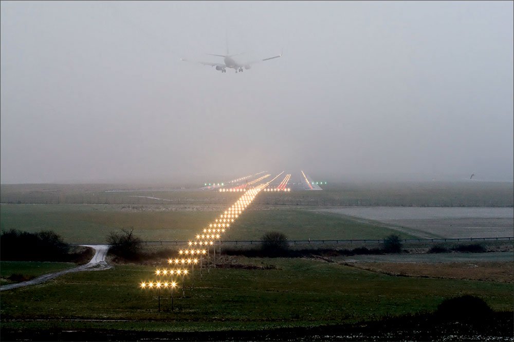
Image disclaimer: For identification and illustration only. It may show a product by another manufacturer and may not depict the exact item described; it is not a statement of any product’s quality, approval or performance. Third-party image and trademark rights belong to their owners. See full notice.
What Is It?
Approach lighting extends outward from the runway threshold along the extended runway centreline, giving a pilot a visual bridge between the end of an instrument approach and the point where the runway environment itself becomes visible. Where runway lighting takes over once the runway is in sight, approach lighting is what gets the aircraft there in the first place under reduced visibility.
The configuration, length and complexity of the approach lighting system are matched to the runway's approach category — a non-precision approach may need only a short, simple system, while a CAT II/III precision approach runway requires an extensive, high-intensity array with crossbars and sequenced flashing lights.
Purpose & Function
Approach lighting's purpose is to bridge the gap between the end of an instrument approach, where the pilot is flying on instruments alone, and the point where the runway environment becomes visually identifiable — a transition that, in low visibility, is exactly where a pilot needs unambiguous visual guidance the most. By presenting a progressively converging, lengthening pattern that resolves toward the threshold, the system gives the pilot confidence that they are aligned and on the correct approach path before the runway itself is in sight, which is why the length and intensity of the system scale directly with approach category — the lower the visibility a runway is certified for, the more of this visual bridge a pilot needs before natural visual reference takes over.
Where Is It Used?
Approach lighting systems are installed on the approach side of runway thresholds serving instrument or precision approaches:
- Approach Light Bars: Rows of lights spaced along the extended centreline, forming the main body of the system.
- Crossbars: Lateral bars at specified distances from the threshold, giving the pilot a horizon/roll reference during approach.
- Centreline Lighting: Reinforces alignment with the runway centreline extended beyond the threshold.
- Sequenced Flashing Lights: Used on higher-category systems, flashing in sequence toward the runway to draw the eye along the approach path.
- Threshold Lighting: Marks the transition point from approach lighting to runway lighting.
System configuration (e.g. simple approach lighting, ALSF-2, CALVERT-type systems) is determined by the runway's approach category under the applicable ICAO or FAA standard.
Installation & Location
The full array is set out along the extended runway centreline beyond the threshold, with each light bar and crossbar positioned at the surveyed distances specified for the runway's approach category, since the system's guidance value depends on that geometry matching the certified design exactly. Structures supporting the lights — individual frangible poles for elevated bars, or inset cans where the terrain allows a flush installation — are set at heights that keep the beam pattern aimed correctly along the approach path while remaining frangible in the event of an aircraft undershoot. Because the array frequently extends off airport property into surrounding terrain, wetlands, or waterways, foundations and access routes are planned around what the specific site allows, sometimes using elevated piled structures over soft ground or water. Power and control cabling for the full array is run back to the approach lighting's own regulator circuits, kept independent from the runway's own lighting circuits so a fault in one system doesn't take down the other during the approach phase where both are needed simultaneously.
How Does It Work?
Approach lighting fixtures — particularly on higher-category systems — sit on elevated structures or frangible masts extending into the approach area, often over difficult or unprepared terrain. Each fixture is still fed through the same series-circuit architecture as runway and taxiway lighting, but approach systems more frequently use higher-intensity fixtures and, where fitted, a separate control system for sequenced flashing lights.
Key functional aspects include:
- Progressive Visual Guidance: The array is read by the pilot as a lengthening, converging pattern that resolves into the runway threshold.
- Sequenced Flashing: On systems that include it, lights flash in a moving sequence toward the runway, strengthening the visual cue in marginal visibility.
- Structural Considerations: Approach lighting structures must be frangible (designed to break away on impact) given their position in the approach obstacle-limitation surface.
- Category-Dependent Length: System length and light density scale directly with the runway's approach category — CAT I, II and III systems are markedly different in extent.
System Architecture & Control Logic
Approach lighting is controlled the same way as runway and taxiway circuits — as a loop, not fixture by fixture — but it is kept on its own dedicated series circuit(s) rather than sharing the runway's loops. An ALCMS or tower command sets the intensity step appropriate to the approach category and prevailing visibility, and this is passed to the approach lighting's own CCR, which regulates the whole loop to the corresponding current. On systems with sequenced flashing lights, a separate sequencing controller drives the flash pattern independently of the fixture intensity itself, so brightness and flash timing can be commanded and monitored as two distinct control functions.
Keeping the approach system's circuit and fault reporting separate from the runway's matters operationally: both systems are needed simultaneously during an approach in low visibility, so a fault on one loop is reported and can be worked on without affecting the other.
ALCMS → Approach CCR → (Sequencing Controller) → Isolating Transformer → Fixture (loop-level feedback)
Circuit & System Overview
The approach lighting array is read as a single converging picture rather than as individual fixtures — light bars lengthening, a crossbar establishing the horizon, and (where fitted) a flashing sequence drawing the eye forward — resolving into the threshold before runway lighting takes over.
Physical Construction
The physical system is built from individual lamp heads and light bars, each of standard frangible-pole or inset-fixture construction, but assembled across a dedicated structure of piers, frangible poles, or — where the approach crosses water, wetlands, or a road — raised platforms and bridge-type supports tied to a common foundation line. Where elevated, every pole in the array shares a frangible coupling near its base so the structure yields safely on impact rather than presenting a rigid obstruction; where terrain allows, sections may instead use inset cans consistent with taxiway or runway practice. Cabling for the full array runs in duct or cable tray along the pier line back to the approach lighting's own control cabinet, with an isolating transformer at each fixture and, on systems with sequenced flashing lights, a separate control cable run alongside the series-circuit power feed for the flasher timing signal. Foundation design, pier spacing, and support-structure type are driven site-by-site by what the specific terrain under the approach path allows.
Technical Parameters
| Parameter | Typical Value |
|---|---|
| System Types | ICAO: simple approach lighting system; precision approach CAT I, and CAT II/III systems (Calvert-type centreline and crossbars). FAA: ALSF-1, ALSF-2, MALSR, MALSF, SSALR, SSALF, ODALS |
| Typical Length | ICAO simple system: centreline ≥ 420 m from threshold (900 m preferred). ICAO precision CAT I/II/III: 900 m. FAA ALSF-2: 2,400 ft (≈720 m); MALSR: 2,400 ft including the RAIL section |
| Crossbar Colour | Variable white centreline and crossbars. CAT II/III systems add red side row barrettes over the inner 270 m, and FAA ALSF-2 adds red side rows plus a red terminating bar |
| Sequenced Flashing Lights | Not category-exclusive — fitted to ALSF-1 (CAT I) and MALSR (non-precision/CAT I) as well as ALSF-2. Under ICAO they may be added to an approach lighting system where an operational need is identified |
| Structure Type | Frangible masts / elevated structures in the approach obstacle-limitation surface |
| Circuit Type | Series circuit fed by CCR, with separate control for sequenced flashing where fitted |
| Intensity Steps | Five steps on the steady-burning approach lighting CCR (100 / 30 / 10 / 3 / 1% of rated intensity). Sequenced flashers, where fitted, have their own three-step control |
| Standards | ICAO Annex 14 Vol I Ch. 5 and Appendix 2; FAA AC 150/5340-30; EASA CS-ADR-DSN; IEC 61827 |
Electrical Requirements
| Requirement | Typical Value |
|---|---|
| Circuit Type | Series circuit, constant current (CCR fed); sequenced flashers on a separate control circuit where fitted |
| Rated Series Current | 6.6A (3 to 5-step: 2.8A / 3.4A / 4.1A / 5.2A / 6.6A) |
| Isolation | Each luminaire fed via a dedicated isolating transformer, not directly connected to the series loop |
| Cable Type | L-824 single-conductor, direct-burial rated, 5kV or 600V per circuit design |
| Connector | L-823 primary connector, submersible-rated splice |
| Insulation Resistance | ≥ 50 MΩ (megger test, cable-to-ground) |
| Earthing/Grounding | Mast/structure and base cans bonded to the airfield earth grid, with lightning protection on elevated frangible masts |
| Fault Protection | CCR-level ground fault and open-circuit detection |
| Sequenced Flasher Control | Separate low-voltage trigger circuit from a flasher controller, synchronised along the approach run |
| Power Source | CCR output, regulated per ICAO/FAA intensity step schedule |
Photometric Requirements
| Parameter | Typical Value |
|---|---|
| Main Beam Intensity (White, Centreline/Crossbar) | ≥ 12,000 cd on-axis, up to 20,000 cd at full intensity |
| Main Beam Intensity (Red, Side/Terminating Row) | ≥ 5,000 cd on-axis, up to 8,000 cd at full intensity |
| Sequenced Flasher Intensity | Specified as effective intensity (Blondel–Rey, 0.2 s constant), not peak candela — 15,000 cd unidirectional high step under the FAA discharge flashing light specification, with medium and low steps at 1,500 cd and 300 cd |
| Beam Pattern | Unidirectional, aimed along the extended runway centreline within the approach obstacle-limitation surface |
| Isocandela Distribution | Per ICAO Annex 14 Vol I Appendix 2 isocandela diagrams for approach centreline and crossbar lights, or the equivalent FAA figures for the system type |
| Chromaticity | Within the ICAO Annex 14 Appendix 1 white or red boundary as applicable (CIE coordinates) |
| Flash Rate (Sequenced Units) | The sequence repeats twice per second (120 cycles/min) in ALSF and MALSR/RAIL installations, and once per second in ODALS — a fixed characteristic, not an adjustable range |
| Intensity Tolerance | ± 25% of rated value at each CCR step (field measurement) |
| Serviceability Threshold | A light is treated as unserviceable when its main beam average intensity falls below 50% of the specified value — and for CAT II/III operations Annex 14 sets minimum percentages of serviceable approach lights that must be maintained, so the count of failed units matters as much as the output of any one |
| Test Method | Mobile photometric van/goniophotometer or fixed test bench, per fixture and row |
Applicable Standards
ICAO Annex 14
International standards for approach lighting configuration by approach category
FAA AC 150/5340-30
Design and Installation Details for Airport Visual Aids (covers approach lighting configurations including MALSF, ALSF-2, and ODALS)
IS 7785 (Part 1)
Elevated type aerodrome lighting fittings — general requirements (Bureau of Indian Standards). Note it covers fitting construction, not approach lighting system geometry
ICAO Doc 9157 Part 4
Aerodrome Design Manual, Visual Aids — approach lighting design guidance and configuration drawings
EASA CS-ADR-DSN
Certification specifications for aerodrome design — Book 1 visual aids
FAA AC 150/5345-51
Specification for Discharge-Type Flashing Light Equipment — applies where sequenced flashers are fitted
DGCA CAR Section 4
Indian regulatory requirements for aerodrome lighting
Note on figures: the values on this page are typical reference figures drawn from the standards listed above and from manufacturers’ published data. Requirements differ between ICAO, FAA and national regimes, and between aerodrome code numbers, approach categories and equipment types. Always design, install, commission and maintain to the project specification, the manufacturer’s manual and the standard in force at the aerodrome.
Installation Requirements
Foundation & Pier Line Set-Out
CivilSurvey and set out the pier or pole foundation line to the design spacing before any structure is cast, since foundation design and support-structure type are driven site-by-site by the terrain under the approach path.
Water/Wetland/Road Crossing Structures
CivilWhere the approach crosses water, wetlands, or a road, install the raised platform or bridge-type support tied to the common foundation line before fixtures are mounted.
Duct/Tray Run Along Pier Line
ElectricalLay cabling in duct or cable tray along the full pier line back to the approach lighting's own control cabinet, keeping the run continuous across every pier in the array.
Per-Fixture Isolating Transformer
ElectricalInstall and terminate an isolating transformer at each fixture per standard series-circuit practice, matched to the lamp head or light bar it feeds.
Sequenced Flasher Control Run
ElectricalWhere sequenced flashing lights are fitted, install the separate control cable run alongside the series-circuit power feed, keeping the timing signal path distinct from the power path.
Frangible Coupling Fixing
MechanicalTorque each pole's frangible coupling near its base to the specified value, since the structure must yield safely on impact rather than presenting a rigid obstruction.
Pre-Energisation Sign-off
DocumentationRecord pier positions, cable routing, transformer assignments, and frangible coupling torque values as-built before the array is first energised.
Testing & Commissioning
Insulation Resistance Test
Pre-EnergisationMegger-test each series circuit and crossbar feeder before energisation, confirming insulation resistance clears the acceptable minimum along the approach.
Loop Continuity & Resistance Test
Pre-EnergisationVerify series loop continuity end to end for every crossbar and centreline segment, ruling out open circuits before first energisation.
Sequenced Flasher Timing Verification
EnergisationConfirm the sequenced flasher lamps fire in the correct order and timing along the approach, matching the design sequencing rate.
Photometric & Alignment Check
Final AcceptanceMeasure beam intensity and confirm elevation/azimuth of each crossbar and centreline light against the design aiming diagram.
CCR Brightness Step Response
EnergisationCycle the CCR through every intensity step and confirm the full approach lighting array responds correctly at each.
Documentation & As-Built Sign-off
Final AcceptanceRecord insulation, continuity, timing, and photometric readings alongside as-built layout in the commissioning dossier for handover.
Inspection & Maintenance
Structural & Frangible Mast Inspection
AnnualCheck masts and elevated structures for corrosion, wind fatigue, and frangible-coupling condition, since these sit in exposed approach terrain.
Light Bar Alignment Check
Semi-annualConfirm each light bar's aim and spacing remain within tolerance so the converging approach picture is presented correctly to arriving aircraft.
Sequenced Flashing System Test
Semi-annualOn CAT II/III systems, verify the sequencing controller drives the flashing pattern correctly and independently of fixture intensity steps.
Photometric Intensity Check
AnnualVerify crossbar and light bar intensity across all selectable steps against ICAO / FAA thresholds using a calibrated photometer.
Series Circuit & CCR Continuity Check
Semi-annualConfirm the series-circuit loop feeding the array and each fixture's isolating transformer are fault-free, since one open point can affect the whole approach picture.
Access Track & Terrain Check
AnnualInspect approach terrain and access tracks for erosion, vegetation growth, or standing water that could affect structure stability or crew access.
Cable & Connector Inspection
AnnualExamine cable runs and connectors between the CCR feed and each fixture for corrosion or loose crimps, a common source of intermittent faults over long approach runs.
Obstruction Lighting Coordination Check
AnnualConfirm any co-located obstruction lighting on masts remains compliant and doesn't interfere with the approach lighting's intended visual guidance.
Common Field Issues
Structural / Frangibility Damage
Approach lighting structures are exposed to wind, terrain conditions and occasional impact; frangible-mast integrity needs periodic inspection alongside the electrical system.
Cable Runs Over Difficult Terrain
Approach areas often run over uneven or waterlogged ground, making cable protection and drainage a bigger factor here than in runway or taxiway circuits.
Sequenced Flashing System Faults
The separate control system for sequenced flashing lights adds another layer that can fail independently of the underlying series circuit, complicating fault isolation.
Access and Maintenance Difficulty
Approach lighting positions are often the least accessible on the airfield, making routine maintenance and fault response logistically harder than for runway or taxiway fixtures.
Troubleshooting Guide
Frangible Mast Found Compromised on Inspection
Cable Fault on a Run Through Waterlogged Ground
Sequenced Flashing Lights Out of Step or Dark
Delayed Fault Response at Approach Positions
Failure Modes & Root Causes
Structural / Frangible Mast Damage
Cable Fault Over Difficult Terrain
Sequenced Flashing System Fault
LED Module / Isolating Transformer Failure
CCR Regulation Fault
Access and Maintenance Difficulty
Safety & Operational Notes
Series Circuit Isolation
Electrical SafetyApproach lighting light bars run on a constant-current series circuit that can carry several kV across the loop. De-energise and lock out the CCR, then verify zero energy at the fixture before opening a base can or handling cable connectors.
Approach Path Work Coordination
OperationalAny work on the approach lighting system requires ATC coordination and a NOTAM, and personnel and vehicles working under the approach path must stay clear of it while aircraft are landing or departing, since this equipment sits directly beneath low-altitude aircraft on final approach.
Elevated Mast Work
Personnel SafetyUse fall protection and follow the site's work-at-height procedure when servicing a light bar mounted on an elevated frangible mast, and inspect the mast structure for corrosion or cracking before climbing or loading it.
Frangibility Not to Be Defeated
MechanicalNever substitute a frangible coupling or mast fitting with a rigid one, and restore any temporary bracing used during elevated work to its original frangible configuration before returning the mast to service.
Remote Site & Terrain Access
Personnel SafetyPlan for the difficult access and limited vehicle routes typical of positions beyond the aerodrome boundary; carry communication equipment, follow lone-worker procedures where applicable, and account for waterlogged or unstable ground when routing personnel and equipment to the site.
FOD Control at Every Position
OperationalAccount for all tools, fasteners, and gaskets at each fixture and base can worked on, and secure or remove loose material before leaving a position, since approach lighting sites can be harder to revisit quickly if debris is found later.
Insulation Test Before Re-Energisation
Electrical SafetyAfter any cable, connector, or transformer work, megger test the affected series loop before restoring power, particularly on runs crossing waterlogged or unstable ground where a residual fault is more likely.
Restore to Compliant State
ComplianceDo not leave a light bar out of tolerance, at reduced intensity, or with a fault in the sequenced flashing pattern after maintenance; verify conformance across the affected bar before closing out the work and cancelling the associated NOTAM.
Engineering & Expert Notes
Sequenced Flasher Drift Is Easy to Miss Bar-by-Bar
VerificationA single flasher unit running slightly out of sequence timing can still look correct when checked in isolation; the "running rabbit" effect that pilots actually rely on only reveals a timing fault when the full sequence is observed end to end, so verify sequence timing across the whole array, not one light bar at a time.
Waterlogged Ground Degrades Foundations Before Cables
CivilOn approach lighting sited over soft or seasonally waterlogged terrain, foundation settlement at individual mast positions tends to show up before cable insulation faults do; a light bar that's drifted slightly out of its aiming tolerance is often a foundation or mast-lean issue rather than an optical or electrical one.
Voltage Drop Compounds Over Long Feeder Runs
ElectricalApproach lighting positions furthest from the CCR or feeder point can run measurably dimmer than nearer fixtures even when every unit tests individually within spec, simply from accumulated voltage drop across a long series run; check output at the far end of the array specifically rather than relying on a spot check near the threshold.
Frangible Mast Fatigue Accumulates From Wind, Not Just Impact
MechanicalElevated frangible masts flex continuously under normal wind loading over years of service, which can fatigue the frangible coupling's shear characteristics well before any impact event; include torque/shear verification in the overhaul cycle for masts at exposed, high-wind sites rather than treating frangibility as a one-time install check.
Access Difficulty Should Drive Inspection Frequency
MaintenancePositions with the hardest vehicle access, often the furthest from the threshold, are also the ones most likely to get skipped or rushed on a routine walk-down; weight inspection planning toward these remote positions specifically, since a fault there is both more likely to go unnoticed and slower to fix once found.
Trend Insulation Readings on Remote Runs
TroubleshootingCable runs crossing unstable or waterlogged ground develop insulation faults gradually rather than suddenly; logging megger readings over successive maintenance cycles on these specific runs catches a developing fault months before it takes the array down.
Frequently Asked Questions
Short answers about approach lighting systems: layout, categories, structures, standards and maintenance.
Q1What is approach lighting?
Approach lighting extends outward from the runway threshold along the extended centreline. It gives pilots a visual bridge between the end of an instrument approach and the point where the runway environment becomes visible.
Q2What are the components of an approach lighting system?
Approach light bars along the extended centreline, crossbars at set distances from the threshold, centreline lighting, and on higher-category systems sequenced flashing lights.
Q3How long is an approach lighting system?
It depends on the approach category. The page gives an ICAO simple system centreline of at least 420 m from the threshold (900 m preferred), with longer and more complex layouts for precision approach CAT I and CAT II/III systems.
Q4What do sequenced flashing lights do?
They flash in sequence toward the runway threshold, strengthening the visual cue in marginal visibility. The page notes they are not exclusive to one category and can be fitted to CAT I and non-precision systems as well.
Q5How are approach lights mounted?
On elevated structures or frangible masts in the approach area, often over difficult or unprepared terrain. Each fixture is still fed through the series circuit.
Q6Which standards apply to approach lighting?
The main references are ICAO Annex 14, FAA AC 150/5340-30, IS 7785 Part 1 for India and ICAO Doc 9157 Part 4.
Q7How often should approach lighting be maintained?
Typically annual structural and frangible mast inspections, and semi-annual light bar alignment checks and sequenced flashing system tests where fitted.
Q8What are the common problems with approach lighting?
Structural or frangibility damage from wind and terrain, cable runs over uneven or waterlogged ground, faults in the separate sequenced flashing control system, and difficult access to many approach lighting positions.
Related Components
Go Beyond the Component. Understand the Complete AGL System.
You have explored the component. Now understand how it works within the complete Airfield Ground Lighting system.
Learn AGL from fundamentals to design, installation, testing, photometry, commissioning, maintenance and troubleshooting through structured technical training at Precision AGL Academy.
Build practical knowledge. Understand the circuit. Read the standards. Troubleshoot with confidence.
Your next step in AGL starts here.
Need help with approach lighting system selection or category compliance?
Precision AGL Academy advises on approach lighting configuration, structural considerations, and standards compliance across ICAO, FAA and Indian requirements.
Follow the Academy
Important Notice, Disclaimer & Limitation of Liability
Please read before relying on any content on this page.
- Purpose and intended users. This page on Approach Lighting is an independent educational and informational reference for competent, suitably trained and authorised airfield ground lighting (AGL) and aerodrome electrical personnel. It is not professional engineering, legal or regulatory advice, and using it does not create any professional or client relationship.
- Safety. Work on series circuits, constant current regulators (CCRs), isolating transformers, cables, connectors and lighting equipment can be fatal. Always apply the aerodrome’s permit-to-work and isolation/LOTO procedures, prove dead, use correctly rated instruments and PPE, and follow the manufacturer’s instructions. Nothing here authorises work on live equipment or the bypassing of any safety device or interlock.
- Aviation operations. Nothing here authorises installation, modification, energisation, adjustment, return to service, a change of operating category (CAT I/II/III), a NOTAM or any aerodrome certification or approval decision. These rest with the aerodrome operator, the air navigation service provider and the competent regulator.
- Specifications, ratings and typical values. Descriptions, parameters, ratings, dimensions, photometric values, wattages, service lives, maintenance tasks and intervals, failure modes, certifications (for example CE, FCC, UL or IEC marks) and part or type designations are general, typical and indicative. They may not match any particular product, make, model or version, and they are not a datasheet, design, specification, selection, sizing, procurement or acceptance criterion. The manufacturer’s current documents, the approved design and the project specification prevail.
- Standards and regulations. References to ICAO, FAA, IEC, IEEE, ISO, BIS, DGCA and other standards are paraphrased summaries for orientation only. They may be incomplete or out of date, and standards are revised from time to time. Consult the current official editions. Following this content does not guarantee compliance with any law, standard or regulatory approval, and the regulator’s requirements always prevail.
- No warranty. Content is provided “as is” and “as available”, without warranty of any kind, express or implied, including accuracy, completeness, currency or fitness for a particular purpose. Real installations differ in design, equipment make and model, age and condition.
- Limitation of liability. To the fullest extent permitted by applicable law, Precision AGL Academy, Precision AGL Solutions and their owners, authors and contributors are not liable for any injury, death, loss, damage, downtime, penalty or regulatory consequence, whether direct or indirect, arising from the use of, reliance on, or inability to use this content. Nothing in this notice excludes or limits any liability that cannot lawfully be excluded or limited.
- Independence, brands and no endorsement. This is an independent publication. It is not affiliated with, sponsored by or endorsed by ICAO, the FAA, the IEC, DGCA, AAI, any airport, regulator, supplier or equipment manufacturer. Third-party names, product designations, standard designations and trademarks (including Megger®, Siemens, Eaton, Crouse-Hinds, ADB SAFEGATE, Fluke, ABB and Honeywell) belong to their respective owners and are used only for identification and description. Mention of a brand, product or supplier is not a recommendation, and we do not sell, supply or quote for any component described.
- Images and third-party content. Images and illustrations are shown to help identify the type of component. They may show products of various manufacturers, may not depict the exact item described, and are not a statement about any product’s quality, approval or performance. Copyright and trademarks in third-party images, logos and photographs belong to their respective owners and are not claimed as ours. If you are a rights holder and want an image removed, replaced or credited, email precisionaglsolutions@gmail.com with the page address and we will act promptly.
- Training and services. Mentions of training, courses, consultation, advice, selection, installation, calibration or other support, including the “Learn…Certify” pathway, describe learning stages and are not an offer, quotation, tender or promise of any result. Contacting us or our replying creates no engagement or duty of care; an engagement exists only under a written agreement. We are not a regulator or certification body, and completing any course or reading this content is not a certification, accreditation or authorisation to work on any aerodrome.
- Copyright, privacy and corrections. © 2026 Precision AGL Academy. All rights reserved. Text, structure, compilations and diagrams may be viewed for personal reference and internal training only; any other copying, republication or commercial use needs our written permission. If you email, telephone or message us, we use your details only to respond and handle your matter, in line with applicable Indian law including the Digital Personal Data Protection Act, 2023; please do not send confidential or security-sensitive information. To display this page your browser requests fonts, icons and images from third-party servers, which receive your IP address and browser details under their own policies. Content is reviewed periodically with no obligation to update. To report an error, safety concern or rights issue, write to precisionaglsolutions@gmail.com.