Beacon Drive Motor
The electric motor that provides the rotational power for airport, heliport, and obstruction beacons. Typically an AC synchronous or DC brushless motor with integrated gearbox, delivering precise speed control, high torque, and reliable 24/7 operation in all weather conditions.
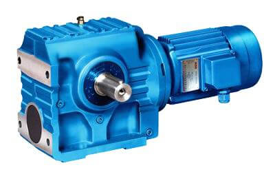
Image disclaimer: For identification and illustration only. It may show a product by another manufacturer and may not depict the exact item described; it is not a statement of any product’s quality, approval or performance. Third-party image and trademark rights belong to their owners. See full notice.
What Is It?
A Beacon Drive Motor is a specialized electric motor used to rotate the optical assembly of airport, heliport, and obstruction beacons. It provides the precise rotational speed (typically 12–15 RPM) required to produce the characteristic flash rate of 24–30 flashes per minute. The motor is usually an AC synchronous motor or a DC brushless motor with an integrated gear reduction system, ensuring consistent speed regardless of load variations. It is designed for continuous operation in harsh outdoor environments, with sealed bearings, weatherproof housing, and thermal protection. The motor is controlled by a beacon controller that regulates speed, monitors current, and detects faults.
Purpose & Function
The drive motor's purpose is to convert a regulatory requirement — a precise flash rate of 24–30 flashes per minute — into a mechanical reality, since the beacon's entire identification function depends on that rate being consistent regardless of wind loading, temperature, or bearing wear over years of continuous outdoor operation. If the rotation speed drifted, the beacon's characteristic flash pattern would drift with it, potentially blurring the distinction between an airport beacon and other rotating or flashing lights in the pilot's field of view. This is why the motor is specified as a synchronous or brushless design with integrated gear reduction rather than a simpler variable-speed motor: consistent speed under load, not raw power, is the actual functional requirement the fixture exists to satisfy.
Where Is It Used?
Used as the prime mover in all rotating beacon systems: airport identification beacons (green/white), heliport beacons (white/yellow), water airport beacons (yellow/white), and obstruction beacons (red/white). Installed inside the beacon housing, connected to the rotating turntable via a gearbox or direct drive. Used in both new installations and as replacement parts for existing beacons. The motor is sized to handle the inertia of the rotating assembly, including lamps, reflectors, and filters.
Installation & Location
The motor is mounted inside the beacon housing on a rigid sub-frame, coupled directly (or via a gearbox) to the rotating turntable that carries the lens assembly and light source. Mounting is set out so the motor shaft aligns precisely with the turntable's axis of rotation, with the gearbox sized and shimmed to eliminate backlash that would otherwise show up as flicker or speed variation in the beam. The motor's power and control leads are wired back to the beacon controller, which regulates speed and monitors current draw. Sealed bearings and a weatherproof housing allow the motor to be installed within the same enclosure as the optics without a separate environmental barrier, and thermal protection is fitted given the motor's continuous-duty operation in an enclosed space that can see significant temperature rise.
How Does It Work?
The beacon drive motor operates by converting electrical energy into mechanical rotation. In an AC synchronous motor, the rotor locks onto the rotating magnetic field of the stator, maintaining a constant speed determined by the line frequency (e.g., 60 Hz yields 12 RPM with a suitable gear reduction). In a DC brushless motor, an electronic controller commutates the windings to achieve precise speed control. The motor drives a gear train (typically worm or planetary gears) that reduces the high speed of the motor (e.g., 1500 RPM) to the required 12–15 RPM. The output shaft is connected to the beacon turntable. The motor includes thermal overload protection, and its current draw is monitored by the beacon controller for fault detection. Sealed ball bearings and grease‑filled gearboxes ensure long maintenance‑free life.
System Architecture & Control Logic
The drive motor has no decision-making of its own — it is commanded entirely by the Beacon Controller and reports back through a single channel: current draw. An AC synchronous motor is inherently open-loop: once it locks onto the rotating magnetic field of the line supply, its speed is fixed by line frequency and gear ratio, so there is nothing for the controller to actively regulate beyond switching power on or off. A DC brushless motor works differently — its own electronic commutation module runs a closed loop internally, typically via Hall-effect sensors, to hold a precise speed regardless of load, so the controller sets a speed reference and the motor's own drive electronics handle the moment-to-moment correction. Either way, current draw is continuously monitored upstream by the beacon controller: rising current with no corresponding rotation points to a mechanical jam or bearing failure, while current that stays high after startup can indicate gearbox binding or an overloaded motor. The motor itself does not generate a fault code — it simply draws current abnormally, and it is the controller that interprets that pattern and escalates it as an alarm to the ALCMS.
Beacon Controller → Motor (AC or DC) → Gear Train → Output Shaft (with current feedback to Controller)
Power-to-Rotation Path
Physical Construction
The drive motor is an AC synchronous or DC brushless unit housed in a sealed, corrosion-resistant metal casing rated IP66/IP67, mounted directly beneath the beacon's rotating turntable inside the tower or pedestal structure. Output shaft speed is stepped down from the motor's native running speed through a worm or planetary gear reduction stage housed in an oil- or grease-lubricated gearbox, coupling to the turntable via a keyed shaft or flange coupling designed to transmit steady torque under continuous duty. Sealed, lifetime-lubricated ball bearings support the shaft at both the motor and gearbox output to minimise maintenance and resist the vibration of continuous rotation. Class F or higher insulation on the windings, combined with the sealed enclosure, protects the motor from moisture, dust, and temperature extremes at typically elevated, weather-exposed mounting locations. A shaft encoder or synchro pickup is commonly integrated to feed rotational speed and position feedback back to the beacon controller for closed-loop speed regulation.
Technical Parameters
| Parameter | Typical Value |
|---|---|
| Motor Type | AC synchronous or DC brushless |
| Input Voltage | 230V AC (single‑phase) or 24V DC |
| Output Speed | 12–15 RPM (after gear reduction) |
| Motor Speed | 1500–3000 RPM (before reduction) |
| Gear Reduction Ratio | 100:1 to 250:1 (worm or planetary) |
| Torque | 5–20 Nm (depending on beacon size) |
| Power Rating | 50–200 W |
| Protection Class | IP66 / IP67, weather‑resistant |
| Insulation Class | Class F (155°C) or higher |
| Bearings | Sealed ball bearings (lifetime lubricated) |
Electrical Requirements
| Requirement | Typical Value |
|---|---|
| Circuit Type | Dedicated motor circuit fed from the Beacon Controller's variable frequency drive or DC output |
| Input Voltage | 230V AC (single-phase) or 24V DC, per motor variant |
| Starting Current | Inrush current several times rated running current; controller sized to accommodate soft-start |
| Control Signal | VFD or PWM speed-control signal from the Beacon Controller, maintaining 12–15 RPM output |
| Insulation Class | Class F (155°C) or higher |
| Cable Termination | IP-rated glanded entry at the motor terminal box, sized for continuous rotating-duty cable flex |
| Earthing/Grounding | Motor frame bonded to the beacon housing and airfield earth grid |
| Fault Protection | Overload and thermal protection at the controller, with loss-of-rotation feedback |
Photometric Requirements
| Parameter | Typical Value |
|---|---|
| Rated Rotation Speed | 12–15 RPM, the speed on which the beacon's flash rate directly depends |
| Speed Regulation Accuracy | ± 1% of rated RPM under normal load, to hold a consistent flash rate |
| Resulting Flash Rate | 24–30 flashes per minute at rated speed (2 flashes per revolution, typical rotating-beacon configuration) |
| Speed Stability Under Load | Maintains set speed across wind loading and bearing wear until service is due |
| Start-Up Time to Rated Speed | Reaches rated RPM within the soft-start ramp defined by the Beacon Controller |
| Loss-of-Rotation Detection | Feedback signal to the controller if speed falls outside tolerance or motor stalls |
| Applicable Photometric Reference | Rotation speed sized to meet ICAO Annex 14 / FAA AC 150/5345-12 beacon flash-rate requirements |
| Test Method | Rotation speed verified under load at commissioning and annual maintenance |
Applicable Standards
IEC 60034
Rotating electrical machines – performance and safety
FAA AC 150/5345-12
Beacon drive motor requirements
UL 1004
Electric motor safety standards
Installation Requirements
Shaft & Coupling Alignment
MechanicalAlign the motor/gearbox output shaft to the turntable coupling within the manufacturer's tolerance, checking for radial and angular runout that could load the bearings or induce vibration.
Gearbox Lubrication Check
MechanicalConfirm the worm or planetary gear reduction stage is filled to the correct oil or grease level before first run, since dry running quickly damages the reduction gearing.
Mounting Bolt Torque
MechanicalTorque the motor and gearbox mounting bolts to specification, checking the base sits flat and square beneath the turntable to avoid introducing misalignment under running load.
Motor Supply Termination
ElectricalTerminate the motor supply per the wiring diagram, confirming correct phase rotation on AC synchronous units or polarity on DC brushless units before energisation.
Encoder/Feedback Connection
ElectricalConnect the shaft encoder or synchro pickup to the beacon controller, verifying the feedback signal is present before enabling closed-loop speed regulation.
Enclosure Sealing
MechanicalSeal cable glands and confirm the housing gasket seats correctly to achieve the rated IP66/IP67 protection at this typically weather-exposed mounting location.
Manual Rotation Check
MechanicalRotate the turntable by hand before power-up to confirm free movement through a full revolution with no binding, fouled cabling, or obstruction.
Pre-Energisation Sign-off
DocumentationRecord shaft alignment, lubrication check, bolt torque values, and wiring termination as-built before the drive is enclosed and energised.
Testing & Commissioning
Insulation Resistance Test
Pre-EnergisationMegger-test the motor windings before energisation, confirming insulation resistance clears the acceptable minimum ahead of first start.
No-Load Rotation Direction Check
Pre-EnergisationBump-start the motor uncoupled from the turntable to confirm correct rotational direction before final coupling.
Output Shaft Speed Verification
EnergisationWith the motor coupled through its gear reduction stage, confirm output shaft speed matches the design 12–15 RPM.
Current Draw & Thermal Check
EnergisationMeasure running current against the motor's rated draw and monitor case temperature rise under sustained operation.
Gear Backlash & Coupling Alignment Check
Final AcceptanceVerify gear backlash and shaft coupling alignment are within tolerance, since excess play shows up as flicker or speed variation in the beacon flash.
Vibration & Noise Assessment
Final AcceptanceCheck for abnormal vibration or noise during rotation, which can indicate bearing damage, gear wear, or misalignment.
Running-In / Burn-In Test
Final AcceptanceRun the motor continuously for a set burn-in period and re-verify speed stability and current draw before final sign-off.
Documentation & As-Built Sign-off
Final AcceptanceRecord insulation, speed, current, and vibration readings alongside motor serial number in the commissioning dossier for handover.
Inspection & Maintenance
Bearing Condition Check
AnnualListen for noise or vibration and check for play in the shaft; sealed bearings dry out over time and should be replaced on a 5-7 year schedule before they seize.
Gear Backlash Inspection
AnnualCheck worm or planetary gear wear and measure backlash, since gear wear causes speed variation that shows up as an inconsistent flash rate at the beacon.
Output Speed Verification
Semi-annualMeasure output RPM under load and confirm it stays within the specified 12-15 RPM range after gear reduction.
Thermal & Ventilation Check
AnnualConfirm ventilation paths are clear and check winding temperature under running conditions to catch overheating before it triggers a thermal cut-out.
Insulation Resistance Test
AnnualMegger-test motor winding insulation to confirm resistance stays above the minimum for its insulation class, flagging moisture or contamination ingress early.
Mounting & Coupling Check
Semi-annualInspect motor mounts and drive coupling to the beacon shaft for looseness or wear that could introduce vibration or misalignment.
Enclosure & Seal Inspection
AnnualCheck the weatherproof housing and cable entry seals for degradation to keep the IP66/IP67 rating intact.
Common Field Issues
Bearing Wear and Seizure
Continuous rotation leads to bearing wear. Sealed bearings eventually dry out, causing noise, vibration, and eventual seizure. Regular lubrication (if serviceable) or bearing replacement (every 5–7 years) is recommended.
Gear Wear and Backlash
Worm or planetary gears can wear over time, leading to increased backlash and speed variation. Periodic gear inspection and replacement of worn gears is essential for maintaining precise rotation speed.
Overheating and Thermal Overload
Blocked ventilation or high ambient temperatures can cause the motor to overheat, triggering thermal cut‑out. Ensuring proper airflow and using motors with high insulation class can prevent this.
Troubleshooting Guide
Motor Fails to Start / Beacon Not Rotating
Noisy or Vibrating Operation
Speed Variation or Inconsistent Flash Rate
Repeated Thermal Trips
Failure Modes & Root Causes
Bearing Seizure
Winding Failure / Open Circuit
Thermal Cut-Out Nuisance Tripping
Gear Wear / Backlash
Safety & Operational Notes
Electrical Isolation
Electrical SafetyLock out the motor supply at the beacon controller and verify zero energy before disconnecting motor leads or removing the housing; the motor circuit is separate from the lamp circuit and must be isolated independently.
Rotating Parts / Gear Train
MechanicalKeep fingers and tools clear of the gear reduction assembly and coupling; the turntable can continue to coast briefly after power is removed, so confirm it is fully stationary before working on it.
Hot Motor Windings
Personnel SafetyAllow the motor housing to cool after continuous operation before handling; sustained running under load can leave the casing hot enough to burn bare skin.
Confirm Resynchronisation
OperationalAfter a motor replacement, verify the beacon controller re-establishes the correct rotation speed and flash rate before returning the unit to service.
Outage Coordination
OperationalCoordinate the planned downtime with ATC or the site operator where the motor drives a beacon relied on for night identification.
PPE
Personnel SafetyUse insulated tools for electrical connections and appropriate fall-protection PPE where the motor is mounted at height.
Restore to Compliant State
ComplianceConfirm rated RPM and resulting flash rate meet specification before closing out the work.
Engineering & Expert Notes
Current Draw Trends Before Bearings Seize
ReliabilityRising motor current draw at a constant rotation speed is an early sign of bearing drag or gearbox wear, well before the motor actually binds or stops. Logging current and thermal readings across successive services catches a bearing on its way out months before it seizes and stops the beacon entirely.
Manual Rotation Check Reveals What Current Draw Alone Won't
DiagnosticsFeeling for binding or roughness by hand-rotating the de-energised shaft catches localised gear or bearing damage that a current-draw trend can mask if the fault only shows up at one point in the rotation. Combine both checks rather than relying on electrical readings alone to judge mechanical condition.
Alignment Drift Shows Up as Noise Before It Shows Up as Failure
MechanicalShaft and coupling misalignment that develops gradually after installation often announces itself as increased vibration or noise long before it causes measurable speed deviation. Treat a beacon that has become audibly noisier as a prompt to re-check alignment, not just lubrication.
Lubrication Interval Should Follow Duty Cycle, Not the Calendar
MaintenanceA beacon that runs continuously through long winter nights accumulates far more gearbox hours per year than the same fixture at a site with shorter nights, so a fixed calendar lubrication interval under-services the harder-worked unit. Base the interval on logged run-hours where duty cycle varies significantly by site or season.
Encoder Faults Mimic Motor Faults
TroubleshootingOn motors fitted with a speed feedback encoder, a faulty encoder connection can make the controller report an erratic-speed fault that looks identical to genuine bearing or winding trouble. Check encoder/feedback wiring integrity before committing to a motor teardown on a reported speed-regulation complaint.
Thermal Checks Matter More in Enclosed Housings
DesignA drive motor in a sealed, low-ventilation housing runs measurably hotter for the same load than an equivalent motor in an open turntable base, shortening insulation life even with identical electrical readings. Weight thermal inspection more heavily on enclosed installations rather than applying one inspection interval across all mounting types.
Frequently Asked Questions
Short answers about beacon drive motors: motor type, speed, gearing, standards, maintenance and common faults.
Q1What is a beacon drive motor?
A beacon drive motor is a specialised electric motor that rotates the optical assembly of airport, heliport and obstruction beacons. It delivers the 12–15 RPM needed to produce a flash rate of 24–30 flashes per minute, and is built for continuous outdoor operation.
Q2What type of motor is used in a rotating beacon?
It is usually an AC synchronous motor or a DC brushless motor with an integrated gear reduction. Typical supply is 230 V AC single-phase or 24 V DC, with a power rating of 50–200 W and Class F (155 °C) or higher insulation.
Q3How does a beacon drive motor achieve 12–15 RPM?
The motor runs at about 1500–3000 RPM and a worm or planetary gear train reduces this to 12–15 RPM at the output, with reduction ratios of roughly 100:1 to 250:1. In an AC synchronous motor the speed locks to the line frequency, while a DC brushless motor is commutated electronically.
Q4Why does the rotation speed matter?
The beacon's flash rate depends directly on rotation speed. Speed is held within ±1% of rated RPM so the flash pattern stays consistent despite wind loading, temperature and bearing wear. Drift would blur the characteristic pattern that pilots use to identify the beacon.
Q5Where is the drive motor installed?
It is mounted inside the beacon housing on a rigid sub-frame and coupled to the rotating turntable directly or through a gearbox. The shaft must align with the turntable axis, and the gearbox is shimmed to remove backlash that would show up as flicker or speed variation.
Q6What controls the drive motor?
The Beacon Controller supplies a variable frequency drive or PWM speed-control signal, manages the soft-start ramp and provides overload and thermal protection. The motor sends loss-of-rotation feedback to the controller if speed falls outside tolerance or the motor stalls.
Q7Which standards apply to beacon drive motors?
The main references are IEC 60034 (rotating electrical machines, performance and safety), FAA AC 150/5345-12 (beacon drive motor requirements) and UL 1004 (electric motor safety). Always verify the current edition and your approved requirements.
Q8How often should a beacon drive motor be inspected?
Typical intervals are semi-annual for output speed verification under load, and annual for bearing condition, gear backlash, thermal and ventilation checks and insulation resistance testing. Sealed bearings are typically replaced every 5–7 years. Your approved maintenance programme takes precedence.
Q9Why won't a beacon drive motor start?
Common causes are seized bearings, an open winding, a thermal cut-out that has not reset, or loss of supply from the beacon controller. Confirm voltage at the motor terminals, check winding continuity and insulation resistance, and turn the shaft by hand with power off to feel for binding. Clear the cause of overheating before resetting the thermal cut-out.
Q10What causes noisy or vibrating operation in a beacon motor?
Usually sealed bearings that are drying out and starting to wear, or worn worm or planetary gearing with excess backlash. Listening for grinding versus rattling helps separate bearing noise from gear noise. Worn gears also cause speed variation that appears as an inconsistent flash rate.
Related Components
Go Beyond the Component. Understand the Complete AGL System.
You have explored the component. Now understand how it works within the complete Airfield Ground Lighting system.
Learn AGL from fundamentals to design, installation, testing, photometry, commissioning, maintenance and troubleshooting through structured technical training at Precision AGL Academy.
Build practical knowledge. Understand the circuit. Read the standards. Troubleshoot with confidence.
Your next step in AGL starts here.
Need expert guidance on beacon drive motor selection or replacement?
Precision AGL Academy provides advice on motor sizing, gear reduction, and maintenance for rotating beacon systems.
Follow the Academy
Important Notice, Disclaimer & Limitation of Liability
Please read before relying on any content on this page.
- Purpose and intended users. This page on Beacon Drive Motor is an independent educational and informational reference for competent, suitably trained and authorised airfield ground lighting (AGL) and aerodrome electrical personnel. It is not professional engineering, legal or regulatory advice, and using it does not create any professional or client relationship.
- Safety. Work on series circuits, constant current regulators (CCRs), isolating transformers, cables, connectors and lighting equipment can be fatal. Always apply the aerodrome’s permit-to-work and isolation/LOTO procedures, prove dead, use correctly rated instruments and PPE, and follow the manufacturer’s instructions. Nothing here authorises work on live equipment or the bypassing of any safety device or interlock.
- Aviation operations. Nothing here authorises installation, modification, energisation, adjustment, return to service, a change of operating category (CAT I/II/III), a NOTAM or any aerodrome certification or approval decision. These rest with the aerodrome operator, the air navigation service provider and the competent regulator.
- Specifications, ratings and typical values. Descriptions, parameters, ratings, dimensions, photometric values, wattages, service lives, maintenance tasks and intervals, failure modes, certifications (for example CE, FCC, UL or IEC marks) and part or type designations are general, typical and indicative. They may not match any particular product, make, model or version, and they are not a datasheet, design, specification, selection, sizing, procurement or acceptance criterion. The manufacturer’s current documents, the approved design and the project specification prevail.
- Standards and regulations. References to ICAO, FAA, IEC, IEEE, ISO, BIS, DGCA and other standards are paraphrased summaries for orientation only. They may be incomplete or out of date, and standards are revised from time to time. Consult the current official editions. Following this content does not guarantee compliance with any law, standard or regulatory approval, and the regulator’s requirements always prevail.
- No warranty. Content is provided “as is” and “as available”, without warranty of any kind, express or implied, including accuracy, completeness, currency or fitness for a particular purpose. Real installations differ in design, equipment make and model, age and condition.
- Limitation of liability. To the fullest extent permitted by applicable law, Precision AGL Academy, Precision AGL Solutions and their owners, authors and contributors are not liable for any injury, death, loss, damage, downtime, penalty or regulatory consequence, whether direct or indirect, arising from the use of, reliance on, or inability to use this content. Nothing in this notice excludes or limits any liability that cannot lawfully be excluded or limited.
- Independence, brands and no endorsement. This is an independent publication. It is not affiliated with, sponsored by or endorsed by ICAO, the FAA, the IEC, DGCA, AAI, any airport, regulator, supplier or equipment manufacturer. Third-party names, product designations, standard designations and trademarks (including Megger®, Siemens, Eaton, Crouse-Hinds, ADB SAFEGATE, Fluke, ABB and Honeywell) belong to their respective owners and are used only for identification and description. Mention of a brand, product or supplier is not a recommendation, and we do not sell, supply or quote for any component described.
- Images and third-party content. Images and illustrations are shown to help identify the type of component. They may show products of various manufacturers, may not depict the exact item described, and are not a statement about any product’s quality, approval or performance. Copyright and trademarks in third-party images, logos and photographs belong to their respective owners and are not claimed as ours. If you are a rights holder and want an image removed, replaced or credited, email precisionaglsolutions@gmail.com with the page address and we will act promptly.
- Training and services. Mentions of training, courses, consultation, advice, selection, installation, calibration or other support, including the “Learn…Certify” pathway, describe learning stages and are not an offer, quotation, tender or promise of any result. Contacting us or our replying creates no engagement or duty of care; an engagement exists only under a written agreement. We are not a regulator or certification body, and completing any course or reading this content is not a certification, accreditation or authorisation to work on any aerodrome.
- Copyright, privacy and corrections. © 2026 Precision AGL Academy. All rights reserved. Text, structure, compilations and diagrams may be viewed for personal reference and internal training only; any other copying, republication or commercial use needs our written permission. If you email, telephone or message us, we use your details only to respond and handle your matter, in line with applicable Indian law including the Digital Personal Data Protection Act, 2023; please do not send confidential or security-sensitive information. To display this page your browser requests fonts, icons and images from third-party servers, which receive your IP address and browser details under their own policies. Content is reviewed periodically with no obligation to update. To report an error, safety concern or rights issue, write to precisionaglsolutions@gmail.com.