Cable Gland
A mechanical cable entry device that secures and seals the electrical cable as it passes through the housing of an AGL fixture. Provides strain relief, environmental sealing (IP67/IP68), and protection against moisture, dust, and mechanical pull forces.
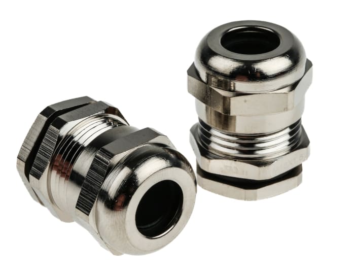
Image disclaimer: For identification and illustration only. It may show a product by another manufacturer and may not depict the exact item described; it is not a statement of any product’s quality, approval or performance. Third-party image and trademark rights belong to their owners. See full notice.
What Is It?
A Cable Gland (also known as a cable connector or cable fitting) is a mechanical device designed to attach and secure the end of an electrical cable to the housing of an AGL fixture, junction box, or control panel. It provides three essential functions: strain relief (preventing the cable from being pulled out of the fixture), environmental sealing (preventing moisture, dust, and contaminants from entering the housing), and electrical continuity (often providing a conductive path for screen/earthing). Cable glands are typically made from brass (nickel-plated), stainless steel, or engineering plastics, with elastomeric seals (O-rings, compression seals) that conform to the cable outer sheath to create a watertight and dust-tight seal. In AGL applications, glands must meet IP67/IP68 ingress protection ratings and withstand harsh environmental conditions, including temperature extremes, UV radiation, and chemical exposure.
Purpose & Function
Every sealed AGL enclosure has to have at least one hole cut into it somewhere for the power cable to get in, and that single opening is where the whole enclosure's IP67/IP68 rating is won or lost. The cable gland's purpose is to close that gap without compromising it: its elastomeric seals grip the cable's outer sheath tightly enough to keep the enclosure watertight and dust-tight at that entry point, while its mechanical clamp takes up any pulling, twisting, or vibration in the cable run so those forces are absorbed by the gland and housing rather than transmitted down the cable to the internal terminations. Where continuity of an earth or screen connection matters, the gland can also carry that electrical path — meaning a poorly fitted or wrong-size gland can defeat the fixture's environmental protection and its earthing at the same time, from a single point of failure.
Where Is It Used?
Cable glands are used at every point where an electrical cable enters an AGL enclosure. Common applications include:
- Fixture Cable Entries: At the bottom housing of runway, taxiway, threshold, and approach lights.
- Junction Boxes: For cable terminations and splices in the series circuit.
- Isolating Transformer Housings: For primary and secondary cable entries.
- CCR Cabinets: For power input and output cable entry points.
- ALCMS Control Panels: For communication and power cable entries.
- Connector Enclosures: For L-823 connector assemblies.
- Obstruction Light Housings: For power and control cable entries.
- Wind Cone and Beacon Housings: For power supply cable entry.
Installation & Location
The gland fits into a threaded or knockout port in the enclosure wall — a fixture's base can, a junction box, or a transformer housing — with the cable's outer sheath clamped inside the gland body so the seal grips the cable jacket rather than the conductors themselves. Gland size is matched to the cable's actual outer diameter rather than a generic fitting, since an oversized gland can't seal properly and an undersized one will crush the cable jacket; orientation is set, where the enclosure allows, so the cable enters from below or the side rather than directly from above, reducing the chance of water tracking down the cable into the gland. Torque on the gland's compression nut is checked to the manufacturer's value and re-checked after the cable has settled in, since underlying cable stress can loosen the gland's grip within the first weeks after installation.
How Does It Work?
A cable gland works by clamping the cable's outer sheath when the gland nut is tightened. The internal components work together to create a secure and sealed cable entry:
- Compression Seal: An elastomeric sealing ring (grommet) is compressed against the cable sheath when the gland nut is tightened, creating a watertight seal that conforms to the cable's outer diameter.
- Strain Relief: The clamping action of the gland body and nut prevents the cable from being pulled out of the housing, protecting the internal electrical connections from mechanical stress.
- O-Ring Seal (Housing Interface): An O-ring or flat gasket between the gland body and the housing provides a seal against moisture ingress at the threaded interface.
- Screen/Earth Continuity: In metallic glands, a conductive path can be established through the gland body to provide earthing for screened cables and EMI protection.
- Swivel or Fixed: Some glands feature a swivel design allowing cable orientation adjustment, while others are fixed-angle.
Proper installation requires matching the gland's cable diameter range to the actual cable diameter, and tightening the nut to the specified torque to achieve the required IP rating without damaging the cable.
System Architecture & Control Logic
The cable gland has no control-logic role — it is a passive sealing point at the boundary between the external field cable run and the protected internal space of whatever enclosure it serves (a base can, CCR cabinet, or junction box). It clamps the cable's outer sheath and seals the entry hole, so its job is to keep the enclosure's interior dry and to relieve strain on the cable's conductors right at the point they cross into the enclosure. Every enclosure containing a cable-fed component in the AGL system uses this same boundary role — the gland has no signal of its own, and its condition (seal integrity, correct cable-diameter match) is checked visually or by inspection rather than through the ALCMS.
A passive seal at the enclosure boundary — its condition is confirmed by inspection, not by any signal to the ALCMS.
How the Seal Is Made
Compression Seal
Elastomeric grommet compresses against the cable sheath
Strain Relief
Gland body & nut clamp the cable against pull-out
O-Ring (Housing Interface)
Seals the threaded joint between gland and enclosure
Earth Continuity
Metallic glands bond the cable screen for EMI protection
Watertight, Strain-Relieved Cable Entry
Correct torque and diameter match are needed to reach the rated IP class without damaging the cable
Physical Construction
The gland body is machined from nickel-plated brass, stainless steel, or moulded polyamide, with a threaded barrel (PG or metric) that screws into the fixture housing or junction box wall and a compression nut at the cable-entry end. Inside, a soft elastomeric sealing ring, silicone, EPDM, or nitrile, is compressed radially around the cable jacket as the nut is tightened, forming the primary seal against water and dust ingress while a separate O-ring seals the gland body to the enclosure wall. An internal shoulder or clamping insert grips the cable to provide strain relief, so pulling forces on the cable are transferred to the gland body rather than the internal terminations. Where specified, a captive metal cone or braid clamp makes contact with the cable's outer screen to provide a bonded earth connection through the gland body itself. Properly torqued and seated against its enclosure gasket, the assembly achieves its rated IP67/IP68 protection.
Technical Parameters
| Parameter | Typical Value |
|---|---|
| Material | Nickel-plated brass, stainless steel (316L), or polyamide (plastic) |
| Thread Type | PG (PG7, PG9, PG11, PG13.5, PG16, PG21) or Metric (M16, M20, M25, M32) |
| Cable Diameter Range | 3-8 mm (PG7) up to 18-28 mm (PG21) |
| Sealing Material | Silicone, EPDM, or Nitrile (NBR) rubber |
| Temperature Range | -40°C to +100°C (depending on material) |
| Ingress Protection | IP67 / IP68 (when properly installed) |
| Strain Relief | Up to 100 N (depending on gland size and cable type) |
| UV Resistance | Excellent (metal), good (UV-stabilised plastic) |
| Chemical Resistance | Resistant to de-icing fluids, jet fuel, hydraulic fluids (varies by material) |
| Earthing/Screen Connection | Optional screen clamp or earth tail |
Applicable Standards
IEC 60529
Degrees of protection provided by enclosures (IP code)
IEC 62444
Performance requirements for cable glands for electrical installations
FAA AC 150/5345-46
Specification for Runway, Taxiway, Heliport, and Vertiport Light Fixtures — includes cable entry and connector requirements for the fixture housing
UL 514B
Conduit, tubing, and cable fittings (US market)
Installation Requirements
Gland Sizing to Cable Diameter
MechanicalMatch the gland size to the cable's actual outer diameter before assembly, since an oversized gland can't seal properly and an undersized one will crush the cable jacket.
Enclosure Port Preparation
MechanicalFit the gland into the enclosure's threaded or knockout port, confirming thread type and port condition before the gland is seated.
Cable Entry Orientation
MechanicalWhere the enclosure allows, orient the cable entry from below or the side rather than directly from above, reducing the chance of water tracking down the cable into the gland.
Housing O-Ring / Gasket Seating
MechanicalSeat the O-ring or flat gasket between the gland body and enclosure wall correctly before final tightening.
Compression Nut Torque Application
MechanicalTighten the gland's compression nut to the manufacturer's specified torque, clamping the cable's outer sheath without damaging it.
Earth / Screen Clamp Connection
ElectricalWhere fitted, connect the screen or earth clamp so continuity runs from the cable screen through the gland body to the enclosure earth point.
Post-Settlement Torque Re-Check
QualityRe-check the compression nut torque after the cable has settled in, since underlying cable stress can loosen the gland's grip within the first weeks after installation.
Pre-Closure Sign-off
DocumentationRecord gland size, thread type, and cable match before the enclosure is closed and backfilled.
Testing & Commissioning
Cable Diameter Match Check
Pre-InstallationConfirm the gland's cable diameter range matches the actual cable outer diameter before assembly, since a mismatch prevents a proper seal.
Gland Nut Torque Verification
Pre-EnergisationTighten the compression nut to the manufacturer's specified torque, achieving the rated IP class without damaging the cable sheath.
Ingress Protection Verification
Final AcceptanceConfirm the sealed assembly meets its rated IP67/IP68 class before the enclosure is closed and backfilled.
Strain Relief Pull Test
Final AcceptanceApply a light tension test on the cable to confirm the clamping insert transfers pulling force to the gland body, not the internal terminations.
Earth/Screen Continuity Test
Final AcceptanceWhere a screen or earth clamp is fitted, verify continuity from the cable screen through the gland body to the enclosure earth point.
Housing O-Ring Seal Check
Pre-EnergisationConfirm the O-ring or flat gasket between the gland body and enclosure wall is correctly seated before final tightening.
Documentation & As-Built Sign-off
Final AcceptanceRecord gland size, thread type, and cable match/IP verification results in the commissioning dossier for handover.
Inspection & Maintenance
Seal Compression Check
AnnualVerify the gland nut is torqued so the internal seal compresses fully around the cable, maintaining the IP67/IP68 rating.
Elastomer Seal Condition
AnnualInspect silicone, EPDM, or nitrile sealing elements for hardening, cracking, or compression set, replacing where they no longer conform to the cable jacket.
Strain Relief Verification
AnnualConfirm the gland still grips the cable to its rated pull-out force, since a loosened strain relief transfers load onto internal terminations.
Thread & Corrosion Check
AnnualCheck gland body threads and housing interface for corrosion or cross-threading damage that could compromise the ingress seal.
Earth / Screen Continuity Test
AnnualWhere fitted, verify the earth tail or screen clamp maintains continuity to the enclosure earth point.
Cable Diameter Match Review
AnnualConfirm the installed cable diameter still falls within the gland's rated clamping range after any cable replacement or re-termination work.
Chemical Exposure Inspection
AnnualCheck for swelling or discoloration from de-icing fluid, jet fuel, or hydraulic fluid exposure that can degrade seal material faster than its rated life.
UV & Material Degradation Check
AnnualInspect plastic-bodied glands for UV embrittlement or chalking, particularly on exposed above-ground fixtures.
Common Field Issues
Moisture Ingress via Gland Seal
If the gland nut is not sufficiently tightened, or if the cable diameter is outside the gland's clamping range, moisture can enter the fixture through the cable entry. This is one of the most common causes of internal corrosion and short circuits. Always verify cable diameter matches the gland's specified range and tighten to the correct torque.
Corrosion of Metal Glands
In coastal or high-humidity environments, brass glands with nickel plating can corrode over time, especially if the plating is damaged. Use stainless steel glands in such environments for maximum durability.
UV Degradation of Plastic Glands
Plastic (polyamide) glands exposed to direct sunlight can become brittle and crack due to UV degradation. Use UV-stabilised plastic glands or metal glands for outdoor airfield installations.
Over-Tightening Damage
Excessive tightening of the gland nut can crush or deform the cable, damage the internal seal, or strip the threads. Always use a calibrated torque wrench and follow the manufacturer's specified torque values.
Incorrect Gland Selection
Using a gland with the wrong thread type (e.g., PG vs Metric) or the wrong cable diameter range can lead to poor sealing and mechanical failure. Always check the fixture's specifications and the cable's outer diameter before selecting a gland.
Troubleshooting Guide
Moisture or Corrosion Found Inside the Fixture at the Cable Entry
Corroded or Discoloured Metal Gland
Plastic Gland Cracked or Brittle
Cable Crushed, Seal Damaged, or Threads Stripped at the Gland
Poor Seal or Mechanical Failure Despite Correct Torque
Failure Modes & Root Causes
Seal Failure from Diameter Mismatch
Metal Gland Corrosion
Plastic Gland Embrittlement
Over-Torque Damage at Installation
Gland Type Mismatch
Safety & Operational Notes
Series Circuit Isolation
Electrical SafetyDe-energise and lock out the circuit and verify zero energy at the connector before removing or refitting a cable gland at any fixture, junction box, or panel entry.
Correct Gland Torque & Sizing
Environmental SealingFit the gland size matched to the cable outer diameter and torque to specification; under-torquing leaves an IP67/68 seal ineffective, while over-torquing can crush the cable jacket and damage the conductors inside.
Verify Seal Before Closing Up
ComplianceInspect the O-ring or compression seal for damage before reassembly, and confirm the gland seats fully against the housing to restore the enclosure's ingress protection rating.
Avoid Dissimilar-Metal Contact
Corrosion ControlMatch gland material to the housing and cable armour where specified, since mixed metals in a damp environment can set up galvanic corrosion that degrades the seal and earth continuity over time.
Insulation Test Before Re-Energisation
Electrical SafetyMegger test the circuit after gland replacement or re-termination before restoring power, since a nicked conductor or damaged seal can fault soon after re-energisation.
PPE & Grounding
Personnel SafetyUse insulated tools when working on series-circuit terminations, and confirm any screen/earth continuity path through the gland is restored before reconnecting.
FOD Control
OperationalAccount for old glands, seals, and fasteners removed during the work, and clear the site before closing out.
Engineering & Expert Notes
Gland Size Must Match the Actual Cable OD, Not the Nominal Size
SealingA gland selected against a cable's nominal diameter rather than its actual measured outer diameter — which varies by manufacturer and batch — can leave the compression seal under- or over-tightened, defeating the watertight function even when installed 'correctly.'
Verify Earthing Continuity Independently of Mechanical Tightness
ElectricalA gland that's mechanically snug and appears well-installed can still fail to provide reliable screen/earth continuity if the conductive path wasn't properly seated during assembly. Test continuity with a meter, don't assume it from correct-looking mechanical assembly.
Re-Torque Compression Nuts After the Cable's First Thermal Cycle
DurabilityCable sheathing can cold-flow slightly under compression during its first significant thermal cycle after installation, leaving the gland's grip looser than at initial torque. A follow-up check after the first season catches this before it becomes a strain-relief or sealing failure.
Match Gland Material to the Housing to Avoid Galvanic Corrosion
MaterialInstalling a brass gland into a housing designed for stainless (or vice versa) sets up galvanic corrosion at the threaded interface, which is difficult to spot until the gland seizes or the seal fails. Confirm material compatibility before substituting a gland from a different batch or supplier.
Bend Radius at the Gland Entry Affects Long-Term Seal Integrity
InstallationA cable bent too sharply immediately at the gland entry puts continuous lateral stress on the seal that a straight entry wouldn't; maintain the manufacturer's minimum bend radius from the gland face, not just from the enclosure wall.
Record Gland Type and Size at Installation for Future Cable Swaps
DocumentationWhen a cable is later replaced with a different type or diameter, having the original gland specification on record prevents a mismatch being installed by a crew unfamiliar with the original design intent.
Frequently Asked Questions
Short answers about the cable gland: what it is, how it works, specifications, standards, maintenance and common faults.
Q1What is a cable gland?
A cable gland (also called a cable connector or cable fitting) attaches and secures the end of an electrical cable to the housing of an AGL fixture, junction box or control panel. It provides strain relief, environmental sealing against moisture and dust, and often a conductive path for screen or earthing.
Q2How does a cable gland seal and hold a cable?
Tightening the gland nut compresses an elastomeric seal against the cable sheath for a watertight seal and clamps the cable to prevent it pulling out. An O-ring or flat gasket seals the interface between the gland body and the housing.
Q3Where are cable glands used in AGL?
At every point where a cable enters an AGL enclosure: fixture cable entries, junction boxes, isolating transformer housings, CCR cabinets and ALCMS control panels.
Q4What materials and thread sizes are typical?
Materials are nickel-plated brass, 316L stainless steel or polyamide, with elastomer seals in silicone, EPDM or nitrile rubber. Threads are PG (PG7 to PG21) or metric (M16 to M32), with cable diameters from 3-8 mm (PG7) up to 18-28 mm (PG21).
Q5What ingress protection and strain relief do AGL cable glands provide?
They typically meet IP67 or IP68 when properly installed, operate from -40°C to +100°C depending on material, and provide strain relief of up to 100 N depending on gland size and cable type.
Q6Why must the gland match the cable diameter?
The compression seal must conform to the cable's outer sheath. A diameter mismatch is a leading cause of seal failure, and choosing the wrong gland type is a common installation error.
Q7Which standards apply to cable glands?
The main references are IEC 60529 (IP codes), IEC 62444 (cable gland performance), FAA AC 150/5345-46 (fixture cable entry requirements) and UL 514B for the US market. Always verify the current edition and your aerodrome's approved requirements.
Q8How often should cable glands be inspected?
Typical annual checks cover seal compression, elastomer seal condition, strain relief, threads and corrosion, earth and screen continuity, cable diameter match, chemical exposure and UV and material degradation. Your airport's approved maintenance programme takes precedence.
Q9What are the common problems with cable glands?
Common problems are moisture ingress through the gland seal, corrosion of metal glands, UV degradation of plastic glands, over-tightening damage (crushed cable, damaged seal or stripped threads) and incorrect gland selection. Moisture or corrosion found inside a fixture at the cable entry is a typical symptom.
Related Components
Go Beyond the Component. Understand the Complete AGL System.
You have explored the component. Now understand how it works within the complete Airfield Ground Lighting system.
Learn AGL from fundamentals to design, installation, testing, photometry, commissioning, maintenance and troubleshooting through structured technical training at Precision AGL Academy.
Build practical knowledge. Understand the circuit. Read the standards. Troubleshoot with confidence.
Your next step in AGL starts here.
Need expert guidance on cable gland selection, installation, or sealing for AGL fixtures?
Precision AGL Academy provides advice on gland materials, torque specifications, and IP sealing best practices.
Follow the Academy
Important Notice, Disclaimer & Limitation of Liability
Please read before relying on any content on this page.
- Purpose and intended users. This page on Cable Gland is an independent educational and informational reference for competent, suitably trained and authorised airfield ground lighting (AGL) and aerodrome electrical personnel. It is not professional engineering, legal or regulatory advice, and using it does not create any professional or client relationship.
- Safety. Work on series circuits, constant current regulators (CCRs), isolating transformers, cables, connectors and lighting equipment can be fatal. Always apply the aerodrome’s permit-to-work and isolation/LOTO procedures, prove dead, use correctly rated instruments and PPE, and follow the manufacturer’s instructions. Nothing here authorises work on live equipment or the bypassing of any safety device or interlock.
- Aviation operations. Nothing here authorises installation, modification, energisation, adjustment, return to service, a change of operating category (CAT I/II/III), a NOTAM or any aerodrome certification or approval decision. These rest with the aerodrome operator, the air navigation service provider and the competent regulator.
- Specifications, ratings and typical values. Descriptions, parameters, ratings, dimensions, photometric values, wattages, service lives, maintenance tasks and intervals, failure modes, certifications (for example CE, FCC, UL or IEC marks) and part or type designations are general, typical and indicative. They may not match any particular product, make, model or version, and they are not a datasheet, design, specification, selection, sizing, procurement or acceptance criterion. The manufacturer’s current documents, the approved design and the project specification prevail.
- Standards and regulations. References to ICAO, FAA, IEC, IEEE, ISO, BIS, DGCA and other standards are paraphrased summaries for orientation only. They may be incomplete or out of date, and standards are revised from time to time. Consult the current official editions. Following this content does not guarantee compliance with any law, standard or regulatory approval, and the regulator’s requirements always prevail.
- No warranty. Content is provided “as is” and “as available”, without warranty of any kind, express or implied, including accuracy, completeness, currency or fitness for a particular purpose. Real installations differ in design, equipment make and model, age and condition.
- Limitation of liability. To the fullest extent permitted by applicable law, Precision AGL Academy, Precision AGL Solutions and their owners, authors and contributors are not liable for any injury, death, loss, damage, downtime, penalty or regulatory consequence, whether direct or indirect, arising from the use of, reliance on, or inability to use this content. Nothing in this notice excludes or limits any liability that cannot lawfully be excluded or limited.
- Independence, brands and no endorsement. This is an independent publication. It is not affiliated with, sponsored by or endorsed by ICAO, the FAA, the IEC, DGCA, AAI, any airport, regulator, supplier or equipment manufacturer. Third-party names, product designations, standard designations and trademarks (including Megger®, Siemens, Eaton, Crouse-Hinds, ADB SAFEGATE, Fluke, ABB and Honeywell) belong to their respective owners and are used only for identification and description. Mention of a brand, product or supplier is not a recommendation, and we do not sell, supply or quote for any component described.
- Images and third-party content. Images and illustrations are shown to help identify the type of component. They may show products of various manufacturers, may not depict the exact item described, and are not a statement about any product’s quality, approval or performance. Copyright and trademarks in third-party images, logos and photographs belong to their respective owners and are not claimed as ours. If you are a rights holder and want an image removed, replaced or credited, email precisionaglsolutions@gmail.com with the page address and we will act promptly.
- Training and services. Mentions of training, courses, consultation, advice, selection, installation, calibration or other support, including the “Learn…Certify” pathway, describe learning stages and are not an offer, quotation, tender or promise of any result. Contacting us or our replying creates no engagement or duty of care; an engagement exists only under a written agreement. We are not a regulator or certification body, and completing any course or reading this content is not a certification, accreditation or authorisation to work on any aerodrome.
- Copyright, privacy and corrections. © 2026 Precision AGL Academy. All rights reserved. Text, structure, compilations and diagrams may be viewed for personal reference and internal training only; any other copying, republication or commercial use needs our written permission. If you email, telephone or message us, we use your details only to respond and handle your matter, in line with applicable Indian law including the Digital Personal Data Protection Act, 2023; please do not send confidential or security-sensitive information. To display this page your browser requests fonts, icons and images from third-party servers, which receive your IP address and browser details under their own policies. Content is reviewed periodically with no obligation to update. To report an error, safety concern or rights issue, write to precisionaglsolutions@gmail.com.