Inset Runway Edge Light
A flush-mounted runway edge light designed for paved surfaces where elevated fixtures are impractical. Provides high-intensity illumination with a low profile, ensuring minimal obstruction to aircraft operations while maintaining precise beam control.
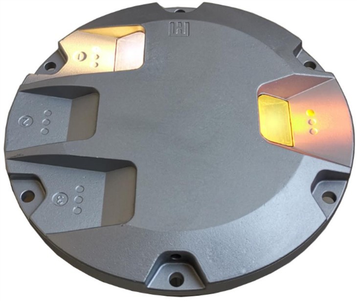
Image disclaimer: For identification and illustration only. It may show a product by another manufacturer and may not depict the exact item described; it is not a statement of any product’s quality, approval or performance. Third-party image and trademark rights belong to their owners. See full notice.
What Is It?
An Inset Runway Edge Light (also known as a flush-mounted runway edge light) is a fixture that sits flush with the runway surface. It is used on paved runways where an elevated light would be a hazard to aircraft (e.g., on narrow shoulders or where snowploughs operate). The fixture includes a rugged housing, a heavy-duty lens, and a precision reflector system to project the required beam pattern. Inset lights are typically used on precision runways (CAT I, II, III) and can be configured for white or yellow (last 600 m / 2,000 ft) light output.
Purpose & Function
The inset configuration exists to deliver the same lateral-guidance function as any runway edge light while removing the fixture as a physical hazard on surfaces where an elevated stem cannot safely be tolerated, such as narrow paved shoulders, overrun areas, or zones serviced by snowploughs and other ground equipment. Because the light sits flush with the pavement, it must be engineered to survive direct wheel loading from the heaviest aircraft using the runway without breaking the optical system or losing its seal, which is why the inset design carries a rugged load-rated housing rather than a frangible coupling. This makes it the preferred choice specifically where mounting constraints, not photometric performance, determine which type of edge light can be installed, and it is the standard fitment on the highest-category precision runways where a raised fixture near the pavement edge would itself present an operational risk.
Where Is It Used?
Installed flush into the runway pavement, typically on the runway edge, at the same spacing as elevated lights (60 m / 200 ft for precision runways). Used on all paved runways where elevated lights are not suitable — such as runways with limited shoulder width, areas where snowploughs operate, or where the aircraft overrun risk is high. Also used on taxiways, aprons, and rapid exit taxiways where a low-profile light is required.
Installation & Location
Fixtures are recessed into an L-868 base can set into the pavement or shoulder, with the top surface finished flush with the surrounding grade to eliminate any obstruction to aircraft wheels. Units are set out at the design spacing along the runway, taxiway, or apron edge, tied to the centreline survey so the line remains parallel and true along its full length. Each base can is sealed against surface water ingress and fed by armoured cable run in a duct or trench back to the isolating transformer, which is housed in its own secondary base can nearby to keep the series-circuit joint clear of standing water. Because inset fixtures carry no frangible requirement, they are the standard choice within the runway end safety area, on rapid exit taxiways, and in other zones where an elevated fitting would pose an obstruction or overrun hazard.
How Does It Work?
Each inset light is powered by the series circuit through an isolating transformer buried beneath the pavement. The fixture uses a high-intensity LED array or halogen lamp with a precision reflector and prism system to create the required photometric output. The light projects a symmetric or asymmetric beam pattern, visible to pilots on approach and during rollout. The rugged housing is designed to withstand repeated direct wheel loading from the heaviest aircraft the runway is rated for, meeting the static and shear load-test criteria set out in FAA AC 150/5345-46 and AC 150/5345-42 for in-pavement fixtures and bases, and includes a pressure vent to equalize internal pressure and prevent moisture ingress.
System Architecture & Control Logic
Inset runway edge lights are not individually addressable — control is exercised at the loop level through the constant current series circuit, exactly as with elevated fixtures. An Airfield Lighting Control and Monitoring System (ALCMS), operated by the tower or an automated visibility-linked routine, selects the required brightness step based on prevailing RVR, ATC instruction, or (at smaller aerodromes) pilot-controlled lighting input. This command is passed to the CCR, which regulates the entire loop to the corresponding fixed current (one of 5 steps between 2.8A and 6.6A). Every inset fixture on that loop, via its own buried isolating transformer, draws from the same current and therefore burns at the same intensity simultaneously — there is no way to dim or brighten a single fixture independently of the rest of the circuit. Fault detection is likewise loop-based: the CCR continuously monitors loop voltage against the commanded current, and a voltage rise at constant current signals increased circuit impedance, typically an open-circuit lamp or a failed isolating transformer, which is reported to the ALCMS as a loop fault rather than pinpointed to an exact fixture without further sectionalised testing. Because inset fixtures see the highest incidence of physical stress from wheel loading, loop testing after a reported fault often starts by isolating the sections nearest known high-traffic crossing points.
ALCMS → CCR → Series Circuit Loop → Isolating Transformer → Inset Fixture (with loop-level feedback)
Circuit & Load Overview
Top row: normal power and beam path from the CCR through to the projected beam. Bottom row: how the inset fixture handles a direct aircraft wheel load — the rugged flush housing absorbs the load in place and the pressure vent equalizes the resulting internal pressure spike, keeping the seal intact.
Physical Construction
The fixture uses a rugged, low-profile die-cast aluminium alloy housing sunk into an L-868 base can recessed into the pavement or shoulder, with the top plate load-rated to withstand repeated aircraft wheel crossings and snowplough blade contact without deformation. The lens sits nearly flush with the top surface, a toughened-glass or high-strength polycarbonate dome shaped to shed water and resist abrasion, backed by a precision prism/reflector assembly that shapes the required beam pattern. The lens-to-housing joint is gasket-sealed with an O-ring for an IP67/IP68 rating, protecting the optics and lamp compartment from surface water, jet-blast debris, and fuel spillage. Because inset units have no elevated stem, there is no frangible coupling; robustness instead comes from the housing wall thickness and the base can's structural fit within the pavement cut-out. Internal leads terminate at L-823 primary connectors, sealed for direct burial and continuous immersion, mating to the isolating transformer's secondary in an adjacent base can, with stainless-steel fasteners resisting corrosion throughout.
Technical Parameters
| Parameter | Typical Value |
|---|---|
| Mounting Type | Flush-mounted (inset) in pavement |
| Light Source | LED array or 50W / 100W halogen |
| Colour | White (full runway), Yellow (last 600m / 2,000ft on CAT II/III) |
| Intensity Steps | 5-step (2.8A – 6.6A) CCR controlled |
| Beam Pattern | Symmetric (3° vertical x 6° horizontal) or asymmetric for approach |
| Load Capacity | Rated for full direct aircraft wheel loading per FAA static/shear load-test criteria |
| Isolating Transformer | 45W / 65W (6.6A series circuit) |
| Protection Class | IP67 / IP68 (submersible, pressure-vented) |
Electrical Requirements
| Requirement | Typical Value |
|---|---|
| Circuit Type | Series circuit, constant current (CCR fed) |
| Rated Series Current | 6.6A (5-step: 2.8A / 3.4A / 4.1A / 5.2A / 6.6A) |
| Isolation | Via dedicated isolating transformer (45W/65W), not directly connected to series loop |
| Transformer Secondary | Matched to fixture wattage; sized to series circuit rating |
| Cable Type | L-824 single-conductor, direct-burial rated, 5kV or 600V per circuit design |
| Connector | L-823 primary connector, submersible-rated splice |
| Insulation Resistance | ≥ 50 MΩ (megger test, cable-to-ground) |
| Earthing/Grounding | Fixture body and base can bonded to airfield earth grid |
| Fault Protection | CCR-level ground fault and open-circuit detection |
| Power Source | CCR output, regulated per ICAO/FAA intensity step schedule |
Photometric Requirements
| Parameter | Typical Value |
|---|---|
| Main Beam Intensity (100%) | ≥ 10,000 cd (white), ≥ 5,000 cd (yellow) per ICAO Annex 14 / IEC 61827 |
| Intensity Steps (5-step) | 100% / 30% / 10% / 3% / 1% of rated peak intensity |
| Vertical Beam Spread | Main beam 1°–15° above horizontal (low-profile lens for flush mounting) |
| Horizontal Beam Spread | ± 5° to ± 7.5° either side of runway centreline plane |
| Isocandela Distribution | Per ICAO Annex 14 Attachment A / FAA AC 150/5345-46 figures |
| Chromaticity (White) | Within ICAO Annex 14 white boundary (CIE coordinates) |
| Chromaticity (Yellow) | Within ICAO Annex 14 yellow boundary (CIE coordinates) |
| Maintenance Factor | ≥ 50% of new-fixture intensity before replacement/cleaning is due |
| Intensity Tolerance | ± 25% of rated value at each CCR step (field measurement) |
| Test Method | Mobile photometric van/goniophotometer or fixed test bench per fixture |
Applicable Standards
ICAO Annex 14
Inset light mounting depths, colours, and photometric requirements
FAA AC 150/5345-46F
Specification for Runway, Taxiway, Heliport, and Vertiport Light Fixtures (covers inset L-868-mounted fixtures; supersedes -46E)
IEC 61827
Electrical and photometric characteristics for inset and elevated AGL luminaires
FAA AC 150/5345-53
Airport Lighting Equipment Certification Program — qualified fixture listing
Installation Requirements
Pavement Cutout & Base Can Setting
CivilCore or saw-cut the recess to the design diameter and depth, then set the L-868 base can true and level so the fixture will sit flush with the finished pavement surface.
Drainage Provision
CivilProvide a weep hole or drainage path at the base can to prevent water pooling around the transformer and cable entry, since flush installations are especially exposed to surface runoff.
Duct & Cable Route
ElectricalLay the series circuit duct/cable route to design depth and separation from other services, avoiding sharp bends that could stress the L-823 connector at final termination.
L-823 Connector Termination
ElectricalTerminate and seal the primary connector per manufacturer procedure, keeping the splice fully submersible-rated before backfill or reinstatement of the base can.
Isolating Transformer Matching
ElectricalConfirm the isolating transformer wattage and ratio match the fixture and the series circuit's rated current step before connection.
Flush-Fit & Sealant Application
MechanicalTorque the fixture fixing bolts to the specified value and apply sealant around the rim, checking the top plate sits flush and load-bearing against repeated wheel and plough contact.
Beam Aim Setting
MechanicalOrient the fixture's beam pattern against the design aiming diagram before final grouting, since orientation cannot be adjusted once the unit is set and sealed.
Pre-Energisation Sign-off
DocumentationRecord base can position, cable route, connector seal, and torque values as-built before backfill, since these are not inspectable once the site is closed.
Testing & Commissioning
Insulation Resistance (Megger) Test
Pre-EnergisationMegger-test the isolating transformer and series loop before the circuit is energised, confirming insulation resistance clears the acceptable minimum.
Loop Continuity & Resistance Test
Pre-EnergisationVerify series loop continuity end to end and record total loop resistance, ruling out open circuits or high-resistance splices before first energisation.
Primary/Secondary Voltage Verification
EnergisationWith the CCR energised, confirm secondary voltage at the L-823 connector matches the transformer's rated ratio at the commissioned current step.
Photometric Intensity Test
Final AcceptanceMeasure beam intensity with a calibrated photometer against ICAO/FAA thresholds before the fixture is handed over.
Pavement Cutout & Sealant Verification
Pre-EnergisationConfirm the recess cutout dimensions and sealant application meet spec before the fixture is finally set and grouted.
Flush-Fit & Levelling Verification
Final AcceptanceConfirm the fixture sits flush with the surrounding pavement surface and within level tolerance across its full diameter.
CCR Brightness Step Response
EnergisationCycle the CCR through every intensity step and confirm the fixture responds correctly at each.
Documentation & As-Built Sign-off
Final AcceptanceRecord insulation, continuity, voltage, and photometric readings alongside as-built position in the commissioning dossier for handover.
Inspection & Maintenance
Lens Inspection
QuarterlyCheck the tempered glass lens for cracks or chips caused by thermal shock or wheel loading, and clean off rubber deposits and grime that dull beam output.
Pressure Vent & Desiccant Check
AnnualVerify the pressure-equalization vent is unblocked and replace the desiccant pack so internal moisture doesn't accumulate and cause corrosion or shorts.
Mounting Bolt Torque Check
AnnualRe-torque heavy-duty mounting bolts to spec and inspect for shear or elongation from repeated aircraft loading, which can tilt the fixture and skew the beam pattern.
Photometric Intensity Check
AnnualMeasure beam intensity and colour with a calibrated photometer against ICAO / FAA thresholds; a shortfall often traces back to lens haze or LED ageing.
Insulation Resistance Test
AnnualMegger-test the isolating transformer and series circuit to confirm insulation resistance stays above minimum, catching moisture ingress before it trips the series circuit.
Pavement Cutout & Sealant Check
AnnualInspect the surrounding pavement cutout and sealant ring for cracking or spalling that could let surface water track down to the fixture housing.
Flush-Fit & Levelling Check
Semi-annualConfirm the fixture top sits flush with the pavement surface with no proud edges or settlement, so wheel loads pass over it without impact damage.
Cable & Connector Inspection
AnnualExamine primary and secondary cable connections in the base for corrosion or loose crimps, a common source of intermittent series-circuit faults.
Common Field Issues
Lens Cracking from Thermal Shock
Inset lights are exposed to extreme temperature variations (hot braking aircraft, cold de-icing fluids). Thermal shock can cause the heavy-duty glass lens to crack. Use of tempered glass and proper thermal management in LED designs is essential.
Moisture Ingress via Pressure Vent
The pressure vent/equalization system is a known weak point. If the vent becomes blocked or fails, moisture can accumulate inside the fixture, leading to corrosion and short circuits. Regular inspection of the vent and desiccant pack is recommended.
Sheared Mounting Bolts
The heavy-duty mounting bolts can shear due to repeated aircraft loading cycles. This can cause the fixture to shift or tilt, altering the beam pattern. A torque-check regime and use of high-strength bolts are recommended.
Troubleshooting Guide
Single Fixture Dark, Rest of Circuit Normal
Entire Series Circuit Dark / CCR Will Not Regulate
CCR Trips on Overcurrent or Ground Fault
Cracked Lens or Reduced Light Output
Fixture Proud of Pavement or Skewed Beam Pattern
Water Pooling or Staining Around the Fixture
Failure Modes & Root Causes
LED Module / Lamp Failure
Isolating Transformer Winding Failure
Cutout Sealant Ring Degradation
Pressure Vent / Desiccant Saturation
Tempered Glass Lens Cracking
Mounting Bolt Shear or Elongation
CCR Regulation Fault
Safety & Operational Notes
Series Circuit Isolation
Electrical SafetyInset edge lights sit on a constant-current series circuit that can carry several kV across the loop. De-energise and lock out the CCR, then verify zero energy at the base can before opening it or handling connectors.
Airside Work Coordination
OperationalAny work on or near an active runway requires ATC/airside coordination and a NOTAM where the fixture will be dark or out of tolerance, with vehicle and personnel movement kept clear of the runway strip.
Flush Fit & Wheel-Load Tolerance
MechanicalThe fixture and lens must sit precisely flush with the pavement or shoulder surface; a proud edge or depression left after reinstatement becomes a wheel-impact and snowplough-catch point as well as a FOD source.
Base Can Seal Integrity
MechanicalReseal the base can lid, lens gasket, and cable gland fully watertight and submersible-rated after any work, since this fitting relies entirely on its seal (rather than elevation) to keep water and jet-blast debris out.
Hot Lamp / Housing Contact
Personnel SafetyAllow the fixture housing and lamp/LED module to cool before handling after an active period; heat can build inside the sealed inset housing and cause burns during lens or lamp replacement.
Insulation Test Before Re-Energisation
Electrical SafetyAfter any cable, connector, or transformer work, megger test the affected series loop before restoring power, since a residual fault at re-energisation can trip the CCR or damage healthy fixtures on the same circuit.
Restore to Compliant State
ComplianceDo not leave a fixture recessed, proud, or at reduced intensity after maintenance; verify flushness and photometric conformance before closing out the work and cancelling the associated NOTAM.
Engineering & Expert Notes
Snowplough Blade Contact Is a Real Load Case
MechanicalBecause the whole point of an inset fixture is surviving direct contact from ground equipment, a snowplough blade catching the lens edge is a normal operating event here, not an anomaly — inspect for chipped or abraded lens rims after each winter season, not only after a reported strike.
Flush Housings Trade Away Passive Heat Dissipation
RetrofitAn elevated fixture sheds heat to open air around the whole housing; a flush-mounted LED module sits recessed in a pavement cut-out with far less convective cooling, so an LED retrofit sized purely on the elevated variant's thermal data can run hotter and age its driver faster in the inset housing. Confirm the retrofit LED module's thermal design accounts for the flush mounting, not just the optical output.
Size the Transformer to the Load, Not the Legacy Lamp
ElectricalReusing an isolating transformer sized for the old incandescent wattage on a much lower-draw LED retrofit is a common source of premature transformer failure and nuisance loop trips; re-select VA rating against the actual LED load rather than assuming the existing transformer is close enough.
Wheel-Load Fatigue Shows Up Before Optical Failure
TroubleshootingBecause the housing itself — not a frangible coupling — carries full wheel loading, fatigue here tends to appear first as hairline lens cracking or base-can seating movement rather than a lighting fault. Weight inspection toward structural signs at high-traffic inset locations, not only photometric output.
Flush Tolerance Is Both a Compliance and a Wear Issue
CivilA fixture sitting even slightly proud of the surrounding pavement takes a sharper edge load every time a wheel crosses it, accelerating housing and seal wear well beyond what the same fixture would see if seated correctly flush. Hold seating tolerance tightly at installation rather than treating a small proud edge as a cosmetic issue to fix later.
Standing Water Reads as a Loop Fault Before It Reads as a Leak
TroubleshootingA degraded base-can seal on a flush fixture often shows up first as a slow insulation-resistance drift on the loop, well before any visible water is apparent at surface level. Trend megger readings at inset locations specifically, since the visual seal check alone can look fine right up until the connector fails.
Frequently Asked Questions
Short answers about the Inset Runway Edge Light (L-868): what it is, how it works, typical specifications, standards, maintenance and common faults.
Q1What is an Inset Runway Edge Light (L-868)?
An Inset Runway Edge Light (also known as a flush-mounted runway edge light) is a fixture that sits flush with the runway surface. It is used on paved runways where an elevated light would be a hazard to aircraft (e.g., on narrow shoulders or where snowploughs operate). The fixture includes a rugged housing, a heavy-duty lens, and a precision reflector system to project the required beam pattern. Inset lights are typically used on precision runways (CAT I, II, III) and can be configured for white or yellow (last 600 m / 2,000 ft) light output.
Q2What is the purpose of an Inset Runway Edge Light (L-868)?
The inset configuration exists to deliver the same lateral-guidance function as any runway edge light while removing the fixture as a physical hazard on surfaces where an elevated stem cannot safely be tolerated, such as narrow paved shoulders, overrun areas, or zones serviced by snowploughs and other ground equipment.
Q3Where is an Inset Runway Edge Light (L-868) used and installed?
Installed flush into the runway pavement, typically on the runway edge, at the same spacing as elevated lights (60 m / 200 ft for precision runways). Used on all paved runways where elevated lights are not suitable — such as runways with limited shoulder width, areas where snowploughs operate, or where the aircraft overrun risk is high. Also used on taxiways, aprons, and rapid exit taxiways where a low-profile light is required.
Q4How does an Inset Runway Edge Light (L-868) work?
Each inset light is powered by the series circuit through an isolating transformer buried beneath the pavement. The fixture uses a high-intensity LED array or halogen lamp with a precision reflector and prism system to create the required photometric output. The light projects a symmetric or asymmetric beam pattern, visible to pilots on approach and during rollout.
Q5What are the typical technical parameters of an Inset Runway Edge Light (L-868)?
Typical values are — Mounting Type: Flush-mounted (inset) in pavement; Light Source: LED array or 50W / 100W halogen; Colour: White (full runway), Yellow (last 600m / 2,000ft on CAT II/III); Intensity Steps: 5-step (2.8A – 6.6A) CCR controlled; Beam Pattern: Symmetric (3° vertical x 6° horizontal) or asymmetric for approach; Load Capacity: Rated for full direct aircraft wheel loading per FAA static/shear load-test criteria; Isolating Transformer: 45W / 65W (6.6A series circuit); Protection Class: IP67 / IP68 (submersible, pressure-vented).
Q6What are the electrical requirements for an Inset Runway Edge Light (L-868)?
Typical requirements are — Circuit Type: Series circuit, constant current (CCR fed); Rated Series Current: 6.6A (5-step: 2.8A / 3.4A / 4.1A / 5.2A / 6.6A); Isolation: Via dedicated isolating transformer (45W/65W), not directly connected to series loop; Transformer Secondary: Matched to fixture wattage; sized to series circuit rating; Cable Type: L-824 single-conductor, direct-burial rated, 5kV or 600V per circuit design; Connector: L-823 primary connector, submersible-rated splice; Insulation Resistance: ≥ 50 MΩ (megger test, cable-to-ground); Earthing/Grounding: Fixture body and base can bonded to airfield earth grid.
Q7What photometric requirements apply to an Inset Runway Edge Light (L-868)?
Typical requirements are — Main Beam Intensity (100%): ≥ 10,000 cd (white), ≥ 5,000 cd (yellow) per ICAO Annex 14 / IEC 61827; Intensity Steps (5-step): 100% / 30% / 10% / 3% / 1% of rated peak intensity; Vertical Beam Spread: Main beam 1°–15° above horizontal (low-profile lens for flush mounting); Horizontal Beam Spread: ± 5° to ± 7.5° either side of runway centreline plane; Isocandela Distribution: Per ICAO Annex 14 Attachment A / FAA AC 150/5345-46 figures; Chromaticity (White): Within ICAO Annex 14 white boundary (CIE coordinates); Chromaticity (Yellow): Within ICAO Annex 14 yellow boundary (CIE coordinates).
Q8Which standards apply to an Inset Runway Edge Light (L-868)?
The main references are ICAO Annex 14 — Inset light mounting depths, colours, and photometric requirements; FAA AC 150/5345-46F — Specification for Runway, Taxiway, Heliport, and Vertiport Light Fixtures (covers inset L-868-mounted fixtures; supersedes -46E); IEC 61827 — Electrical and photometric characteristics for inset and elevated AGL luminaires; FAA AC 150/5345-53 — Airport Lighting Equipment Certification Program — qualified fixture listing. Always verify the current edition and your aerodrome's approved requirements.
Q9How often should an Inset Runway Edge Light (L-868) be inspected and maintained?
Typical maintenance tasks and intervals are: Lens Inspection (quarterly); Pressure Vent & Desiccant Check (annual); Mounting Bolt Torque Check (annual); Photometric Intensity Check (annual); Insulation Resistance Test (annual); Pavement Cutout & Sealant Check (annual); Flush-Fit & Levelling Check (semi-annual); Cable & Connector Inspection (annual). Your airport's approved maintenance programme takes precedence.
Q10How do I troubleshoot common Inset Runway Edge Light (L-868) faults?
Common symptoms covered are: Single Fixture Dark, Rest of Circuit Normal; Entire Series Circuit Dark / CCR Will Not Regulate; CCR Trips on Overcurrent or Ground Fault; Cracked Lens or Reduced Light Output; Fixture Proud of Pavement or Skewed Beam Pattern; Water Pooling or Staining Around the Fixture. For example, for "Single Fixture Dark, Rest of Circuit Normal": Likely Cause: Failed LED module/lamp, or an open isolating transformer (blown primary link or failed secondary winding) inside the fixture housing. Diagnostic Steps: Confirm series loop continuity is unbroken through the transformer primary; megger the transformer; check secondary voltage at the base connector with the CCR energised. Corrective Action: Replace the LED module/lamp if the transformer checks healthy; otherwise swap the isolating transformer and re-seal the housing before reinstating in the cutout.
Related Components
Go Beyond the Component. Understand the Complete AGL System.
You have explored the component. Now understand how it works within the complete Airfield Ground Lighting system.
Learn AGL from fundamentals to design, installation, testing, photometry, commissioning, maintenance and troubleshooting through structured technical training at Precision AGL Academy.
Build practical knowledge. Understand the circuit. Read the standards. Troubleshoot with confidence.
Your next step in AGL starts here.
Need expert advice on inset runway edge light selection or installation?
Precision AGL Academy provides guidance on load ratings, thermal management, and field testing of inset AGL fixtures.
Follow the Academy
Important Notice, Disclaimer & Limitation of Liability
Please read before relying on any content on this page.
- Purpose and intended users. This page on Inset Runway Edge Light is an independent educational and informational reference for competent, suitably trained and authorised airfield ground lighting (AGL) and aerodrome electrical personnel. It is not professional engineering, legal or regulatory advice, and using it does not create any professional or client relationship.
- Safety. Work on series circuits, constant current regulators (CCRs), isolating transformers, cables, connectors and lighting equipment can be fatal. Always apply the aerodrome’s permit-to-work and isolation/LOTO procedures, prove dead, use correctly rated instruments and PPE, and follow the manufacturer’s instructions. Nothing here authorises work on live equipment or the bypassing of any safety device or interlock.
- Aviation operations. Nothing here authorises installation, modification, energisation, adjustment, return to service, a change of operating category (CAT I/II/III), a NOTAM or any aerodrome certification or approval decision. These rest with the aerodrome operator, the air navigation service provider and the competent regulator.
- Specifications, ratings and typical values. Descriptions, parameters, ratings, dimensions, photometric values, wattages, service lives, maintenance tasks and intervals, failure modes, certifications (for example CE, FCC, UL or IEC marks) and part or type designations are general, typical and indicative. They may not match any particular product, make, model or version, and they are not a datasheet, design, specification, selection, sizing, procurement or acceptance criterion. The manufacturer’s current documents, the approved design and the project specification prevail.
- Standards and regulations. References to ICAO, FAA, IEC, IEEE, ISO, BIS, DGCA and other standards are paraphrased summaries for orientation only. They may be incomplete or out of date, and standards are revised from time to time. Consult the current official editions. Following this content does not guarantee compliance with any law, standard or regulatory approval, and the regulator’s requirements always prevail.
- No warranty. Content is provided “as is” and “as available”, without warranty of any kind, express or implied, including accuracy, completeness, currency or fitness for a particular purpose. Real installations differ in design, equipment make and model, age and condition.
- Limitation of liability. To the fullest extent permitted by applicable law, Precision AGL Academy, Precision AGL Solutions and their owners, authors and contributors are not liable for any injury, death, loss, damage, downtime, penalty or regulatory consequence, whether direct or indirect, arising from the use of, reliance on, or inability to use this content. Nothing in this notice excludes or limits any liability that cannot lawfully be excluded or limited.
- Independence, brands and no endorsement. This is an independent publication. It is not affiliated with, sponsored by or endorsed by ICAO, the FAA, the IEC, DGCA, AAI, any airport, regulator, supplier or equipment manufacturer. Third-party names, product designations, standard designations and trademarks (including Megger®, Siemens, Eaton, Crouse-Hinds, ADB SAFEGATE, Fluke, ABB and Honeywell) belong to their respective owners and are used only for identification and description. Mention of a brand, product or supplier is not a recommendation, and we do not sell, supply or quote for any component described.
- Images and third-party content. Images and illustrations are shown to help identify the type of component. They may show products of various manufacturers, may not depict the exact item described, and are not a statement about any product’s quality, approval or performance. Copyright and trademarks in third-party images, logos and photographs belong to their respective owners and are not claimed as ours. If you are a rights holder and want an image removed, replaced or credited, email precisionaglsolutions@gmail.com with the page address and we will act promptly.
- Training and services. Mentions of training, courses, consultation, advice, selection, installation, calibration or other support, including the “Learn…Certify” pathway, describe learning stages and are not an offer, quotation, tender or promise of any result. Contacting us or our replying creates no engagement or duty of care; an engagement exists only under a written agreement. We are not a regulator or certification body, and completing any course or reading this content is not a certification, accreditation or authorisation to work on any aerodrome.
- Copyright, privacy and corrections. © 2026 Precision AGL Academy. All rights reserved. Text, structure, compilations and diagrams may be viewed for personal reference and internal training only; any other copying, republication or commercial use needs our written permission. If you email, telephone or message us, we use your details only to respond and handle your matter, in line with applicable Indian law including the Digital Personal Data Protection Act, 2023; please do not send confidential or security-sensitive information. To display this page your browser requests fonts, icons and images from third-party servers, which receive your IP address and browser details under their own policies. Content is reviewed periodically with no obligation to update. To report an error, safety concern or rights issue, write to precisionaglsolutions@gmail.com.