Isolating Transformers & Series Circuits
The fundamental building blocks of airfield ground lighting — each fixture powered through its own isolating transformer on a shared series loop, delivering fault tolerance, constant current, and uniform intensity across the entire airfield.
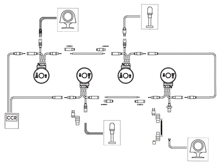
Image disclaimer: For identification and illustration only. It may show a product by another manufacturer and may not depict the exact item described; it is not a statement of any product’s quality, approval or performance. Third-party image and trademark rights belong to their owners. See full notice.
What Are They?
Isolating transformers are the individual power-supply units that feed each AGL fixture (or small group of fixtures) from the primary series circuit. They are typically 1:1 or step-down transformers with a primary winding connected in series with the main loop and one or more secondary windings that supply the lamp or LED module at a lower, safe voltage — the exact secondary voltage depends on the connected fixture's wattage rating, since these transformers are specified by secondary current (typically 6.6A or 20A) and wattage rather than a fixed secondary voltage.
Series circuits are the backbone of AGL power distribution. A constant current regulator (CCR) drives a fixed current (usually 6.6A) through a loop of cable that passes through every isolating transformer in that circuit. Because the current is the same through all series-connected elements, every fixture on that circuit receives the same current, and thus the same intensity, regardless of how many fixtures are installed or how long the cable run is.
This combination — isolating transformers on a series circuit — is what makes AGL systems reliable, scalable, and easy to control. A single CCR can power dozens of fixtures, and a single fixture failure does not take down the whole circuit because the isolating transformer's primary winding remains a low-impedance path for the series current.
Purpose & Function
This combination exists to solve two problems at once that would otherwise be in tension with each other: an airfield needs every fixture on a circuit to receive exactly the same, consistent brightness regardless of its position in the loop, but it also needs a single failed fixture or transformer to never take down every other light sharing that circuit. A series circuit alone would guarantee the first but fail badly at the second — a genuine open circuit anywhere in a pure series loop stops current everywhere. Isolating transformers are what let the loop keep the uniform-current benefit of a series circuit while still tolerating individual fixture faults, because each transformer's primary winding provides a low-impedance path that keeps the loop current flowing even if that fixture's secondary side or lamp has failed.
The isolation itself is equally purposeful from a safety standpoint: each fixture sits electrically separated from every other fixture on the loop, so a technician working on one light, or a fault developing at one location, doesn't expose the rest of the circuit — or the people maintaining it — to that problem. This is what allows a single CCR to reliably drive dozens of fixtures spread across kilometres of airfield, with the confidence that the system as a whole will keep functioning even as individual components inevitably age, fail, and get serviced over the system's operational life.
Where Are They Used?
Isolating transformers are installed at every lighting fixture position across the airfield, buried in below-grade pits or directly embedded with the fixture:
- Runway Edge and Centreline: Each edge light and centreline light has its own isolating transformer, typically mounted in a shallow pit adjacent to the fixture.
- Taxiway Edge and Centreline: Similarly, every taxiway light is fed through its own transformer.
- Approach Lighting: Even elevated approach light structures use isolating transformers, often housed in a base pit.
- Stop Bars and Guard Lights: These critical fixtures also use isolating transformers, often on separately switched series circuits.
- Airfield Signage: Illuminated signs are powered via isolating transformers in the same way as lighting fixtures.
- Primary Series Loop: The transformer primary windings are connected in series with the main cable, forming the continuous loop that starts and ends at the CCR.
The series circuit itself runs between the CCR and the furthest fixture, with the cable passing through each transformer's primary in a daisy-chain fashion (or sometimes in a loop with two feeds for redundancy).
Installation & Location
Each isolating transformer is installed in its own shallow pit or base can immediately adjacent to the fixture it feeds, so the low-voltage secondary run to the lamp or LED module stays short while the primary winding sits in-line with the series cable passing through the pit from the previous fixture to the next. The transformer is positioned above any drainage sump in the pit and set on its mounting bracket clear of standing water, with the primary and secondary connectors made up using L-823 or equivalent watertight couplers before the pit lid is closed. Because the primary winding forms part of the continuous series loop, the transformer's physical position in the daisy-chain has to match the circuit design and as-built drawing exactly, so a technician tracing the loop later can rely on the documented order of fixtures matching what is actually buried in the ground. Where a circuit uses a loop configuration with two feeds for redundancy rather than a single daisy-chain, the two cable runs into and out of each pit are kept clearly identified during installation so the loop's redundancy is not compromised by a mislabelled connection.
How Do They Work?
The isolating transformer is the interface between the high-voltage, low-current series circuit and the low-voltage, high-current fixture. The primary winding is designed to carry the full series current (e.g. 6.6A) with minimal voltage drop, and its inductance presents a relatively high impedance to the series circuit, allowing the transformer to extract power while still passing the current along to the next transformer.
Key functional aspects include:
- Constant-Current Feeding: The transformer steps down the voltage (e.g., from several hundred volts on the primary to a level set by the connected fixture's wattage on the secondary) while stepping up the current, matching the fixture's requirement. The secondary current is proportional to the primary current divided by the turns ratio.
- Fault Isolation: If a fixture or its secondary wiring fails open, the transformer's primary remains intact, so the series current continues to flow. If a secondary short occurs, the transformer's primary impedance limits the current, preventing a total circuit failure.
- Intensity Control: Because all transformers on a given series circuit share the same primary current, adjusting the CCR's output current changes the brightness of every fixture on that circuit simultaneously — this is how intensity steps work.
- Electrical Isolation: The transformer provides galvanic isolation between the primary series circuit and the secondary fixture, improving safety and reducing the risk of shock or earth-leakage faults propagating through the system.
- Multiple Secondary Windings: Some transformers have multiple secondary taps to supply different fixture types (e.g., one for an edge light and one for a sign) from the same primary.
System Architecture & Control Logic
The isolating transformer has no electronics or command input of its own; its place in the system architecture is as the passive interface node between the CCR's series-current control loop and each individual fixture. Because every transformer's primary is wired in series with the same loop, the CCR's constant-current regulation is what actually governs brightness across the whole circuit — the transformer just steps that shared current down to a safe secondary voltage for its fixture, with no local intensity decision to make. This series-primary arrangement doubles as the circuit's built-in fault-isolation logic: an open secondary (a failed lamp) doesn't interrupt the primary loop, so the rest of the circuit keeps operating, while a shorted secondary is limited by the transformer's own impedance rather than collapsing the whole circuit — with any resulting anomaly still surfacing at the CCR as a voltage change against commanded current, exactly as it would for a cable or connector fault.
CCR Series Current → Transformer Primary (in loop) → Secondary Winding → Fixture → Fault Isolation
Series Circuit & Fault Isolation
Physical Construction
An isolating transformer is built around a toroidal or laminated core wound with primary and secondary copper windings, encapsulated in resin or, in older designs, housed in an oil-filled metal casing to provide electrical insulation and protect the windings from moisture during buried service. The encapsulated or oil-filled unit is sized to fit within a standard base can, with primary and secondary leads terminating at sealed L-823 connectors that mate to the incoming series circuit cable and the outgoing fixture cable respectively, keeping every connection point watertight to an IP68 rating. The insulation system between primary and secondary windings is rated to a high dielectric strength, since the transformer's core function is to isolate each fixture electrically from the rest of the series circuit so a fault at one fixture does not propagate along the loop. Class H or higher insulation materials are used throughout to tolerate the sustained thermal loading of continuous series-circuit operation, and the transformer's compact cylindrical or rectangular form factor is designed to sit alongside the fixture's connector and cabling within the confined space of a base can.
Technical Parameters
| Parameter | Typical Value |
|---|---|
| Primary Current (Standard) | 6.6A RMS (series loop current) |
| Primary Voltage (Depends on circuit) | Typically 0–5kV (set by CCR to maintain current) |
| Secondary Voltage (Fixture) | Varies with fixture wattage rating (typically a few volts up to ~30V) — not a fixed value |
| Secondary Current (Fixture) | 6.6A or 20A (matched to the fixture's branch circuit rating) |
| Turns Ratio | Set by primary/secondary current combination and fixture wattage (per FAA L-830 rating tables) rather than a fixed ratio |
| Transformer Type | Toroidal or laminated core, oil-filled or resin-encapsulated for durability |
| Insulation Class | Class H (180°C) or higher for buried service |
| Protection Rating | IP68 (submersible) for underground installations |
| Temperature Range | -40°C to +55°C (ambient) |
| Standards | ICAO Annex 14, FAA AC 150/5345-47C, IEC 61823, IS 12290 |
Electrical Requirements
| Requirement | Typical Value |
|---|---|
| Circuit Type | Series airfield circuit, constant current (CCR fed) |
| Primary Loop Current | 6.6A RMS (series loop) |
| Cable Type | L-824 single-conductor, direct-burial rated on the primary side |
| Connector | L-823 primary connector, submersible-rated splice |
| Dielectric Strength | Rated per insulation class (Class H, 180°C, for buried service) |
| Insulation Resistance | ≥ 50 MΩ (megger test, cable-to-ground) |
| Earthing/Grounding | Case bonded to airfield earth grid; secondary kept isolated from the primary loop |
| Fault Protection | CCR-level ground fault and open-circuit detection on the primary loop |
| Power Source | CCR output, regulated per ICAO/FAA intensity step schedule |
Applicable Standards
FAA AC 150/5345-47C
Specification for Series to Series Isolation Transformers for Airport Lighting Systems
ICAO Annex 14
International standards for AGL electrical systems, including transformer requirements
IEC 61823
Electrical installations for lighting and beaconing of aerodromes — AGL series transformers (the actual transformer design/test standard; IEC 61822 covers the CCR that drives the circuit instead)
IS 12290
Indian Standard specification for isolating transformers for airport lighting systems
DGCA CAR Section 4
Indian regulatory requirements for aerodrome electrical installations
Installation Requirements
Base Can Space & Fit
CivilConfirm the transformer's cylindrical or rectangular form fits alongside the fixture's connector and cabling within the base can before backfill, since it shares the same confined space as the fixture.
Rating & Turns-Ratio Match
ElectricalConfirm the transformer's wattage, turns ratio, and secondary rating match the fixture it feeds and the series circuit's rated current step before connection.
L-823 Primary & Secondary Termination
ElectricalTerminate and seal both the primary (series loop) and secondary (fixture) L-823 connectors to a watertight IP68 rating before the base can is closed.
Series Loop Continuity
ElectricalKeep the primary winding in the series loop path intact end to end, since a broken primary takes the whole circuit down rather than just the one fixture.
Insulation Integrity Check
MechanicalInspect the resin encapsulation or oil-filled casing for damage before installation, since the primary-to-secondary insulation is what isolates each fixture from the rest of the loop on a fault.
Drainage Provision
CivilConfirm the base can drainage path is clear before the transformer and connectors go in, since sustained submersion beyond the IP68 rating shortens service life.
Pre-Backfill Sign-off
DocumentationRecord transformer rating, connector seal, and base can position as-built before backfill, since these are not inspectable once the site is closed.
Testing & Commissioning
Insulation Resistance Test
Pre-EnergisationMegger-test primary and secondary windings of each isolating transformer before backfill, confirming insulation resistance clears the acceptable minimum.
Loop Continuity & Resistance Test
Pre-EnergisationVerify series loop continuity through each transformer's primary winding and record total loop resistance before first energisation.
Turns Ratio Verification
Pre-EnergisationConfirm the actual primary-to-secondary turns ratio matches the nameplate value for the fixture's wattage rating using a turns-ratio or voltage test.
Primary/Secondary Voltage Verification
EnergisationWith the CCR energised at the commissioned current step, confirm secondary voltage at each transformer matches its rated ratio.
Open-Circuit Fault Simulation
EnergisationDisconnect a fixture to simulate an open secondary and confirm the CCR correctly reports a voltage rise / loop fault rather than a silent failure.
Sealing & IP68 Verification
Final AcceptanceConfirm the transformer's enclosure or resin encapsulation is intact and rated IP68/submersible before the unit is buried or placed in its base can.
Documentation & As-Built Sign-off
Final AcceptanceRecord insulation, turns-ratio, voltage, and fault-simulation results alongside as-built transformer positions in the commissioning dossier for handover.
Inspection & Maintenance
Insulation Resistance Test
AnnualMegger-test primary-to-secondary insulation to confirm it holds up to the Class H rating; a falling trend often signals moisture ingress before it causes a fault.
Turns Ratio Verification
AnnualConfirm the transformer still delivers the correct secondary voltage for its turns ratio and the connected fixture's wattage, since a shifted ratio changes fixture brightness or can damage the LED driver.
Seal & Housing Inspection
AnnualCheck the encapsulation or housing for cracking that could compromise the IP68 rating on buried, submersible units.
Terminal Connection Check
AnnualInspect primary and secondary terminal connections for corrosion or loosening, a common cause of intermittent series-circuit faults.
Thermal Performance Check
AnnualCheck for signs of overheating (discoloration, deformed encapsulant) that could indicate a developing winding short or overload condition.
Primary Current Verification
Semi-annualConfirm the transformer maintains correct behavior at the 6.6A RMS series loop current across all CCR-selected intensity steps.
Base Can / Pit Moisture Check
AnnualCheck for standing water in the surrounding base can or pit, which accelerates seal degradation even on IP68-rated transformers.
Fixture Load Compatibility Check
AnnualVerify the transformer's rated wattage still matches the connected fixture load after any fixture upgrade or replacement.
Common Field Issues
Transformer Primary Open Circuit
If a primary winding fails open, the entire series circuit is broken — all fixtures downstream of that transformer will go out. This is why transformer primary continuity is a critical check during fault-finding.
Secondary Short Circuit
A short on the secondary side (e.g., a faulty lamp holder) can overload the transformer, causing overheating and eventual failure, though the primary current remains limited.
Moisture Ingress in Transformer Pit
Despite IP68 ratings, prolonged submersion or damaged cable glands can allow water into the transformer housing, leading to insulation breakdown and earth leakage.
Incorrect Transformer Rating
Using a transformer with the wrong turns ratio or current rating for the fixture type can cause under- or over-driving, reducing lamp life or causing premature failure.
Connector and Cable Joint Degradation
The connections between the series cable and transformer primary, and between the transformer secondary and fixture, are common points of failure — they are addressed in detail in the AGL Connectors page.
Earth Loop and Leakage Currents
Poor earthing or insulation breakdown can cause stray currents that trip CCR earth-leakage protection, requiring systematic insulation-resistance testing of the entire series circuit.
Troubleshooting Guide
Entire Series Circuit Dark / CCR Will Not Regulate
Single Fixture Dark, Rest of Circuit Normal
CCR Trips on Overcurrent or Ground/Earth Fault
Fixture Under- or Over-Driven (Dim, Overheating, or Short Lamp Life)
Fixture Flickering or Intermittent
Transformer Overheating or Housing Discoloration
Failure Modes & Root Causes
Isolating Transformer Winding Failure
Series Cable Insulation Breakdown
Transformer Turns-Ratio Mismatch
L-823 Connector / Splice Degradation
Transformer Overheating
Loop Resistance Creep
Safety & Operational Notes
Series Circuit Isolation
Electrical SafetyAGL series circuits can carry several kV. De-energise and lock out the CCR, then verify zero energy before opening a transformer housing or handling cable connectors.
PPE & Insulated Tools
Personnel SafetyUse insulated tools and appropriate PPE when working on series-circuit connections, and confirm bonding/grounding is intact before reconnecting the loop.
Allow Cool-Down Before Handling
Personnel SafetyAllow the transformer housing to cool before handling after an active period, particularly on high-output-step circuits where the potting compound and casing can retain heat.
Insulation Test Before Re-Energisation
Electrical SafetyMegger test the affected series loop after any transformer, connector, or cable work before restoring power, since a residual fault at re-energisation can trip the CCR or damage healthy equipment on the circuit.
Confirm Turns-Ratio Before Installation
OperationalVerify the transformer's turns ratio matches the fixture's rated lamp/LED current before installation; a mismatched ratio can under- or over-drive the connected fixture.
FOD Control at the Housing
OperationalKeep tools, fasteners, and potting or gasket material accounted for at all times when the transformer housing is open, to prevent foreign object debris on the movement area.
Restore to Compliant State
ComplianceVerify loop resistance and insulation resistance are within tolerance before closing out the work and cancelling any associated NOTAM.
Engineering & Expert Notes
Size the Transformer to the Load, Not the Legacy Lamp
ElectricalReusing an isolating transformer sized for the old incandescent wattage on a much lower-draw LED fixture is a common source of premature transformer failure and nuisance loop trips; re-select VA rating against the actual load rather than assuming the existing transformer is "close enough."
Trend Loop Readings, Don't Just Spot-Check
TroubleshootingMoisture ingress at a connector usually shows up first as a slow drift in loop insulation resistance, not a hard fault. Logging readings over successive maintenance cycles catches a failing splice months before it takes the loop down.
Balance Loops Sharing One CCR
DesignWhere multiple series loops run off a single CCR, unequal loop lengths or transformer counts between loops can produce uneven current distribution and brightness even though each fixture tests within tolerance individually. Balance loop impedance at the design stage, not after commissioning complaints.
Let a Field-Pulled Transformer Reach Ambient Before Testing
TechniqueAn insulation resistance reading taken on a transformer still warm from recent operation tends to read lower than its true cold value. Where a reading is borderline, let the unit cool and retest before condemning it based on a single warm reading.
Moisture Skews Readings More Than Winding Damage
DiagnosticsLow insulation resistance on a field-pulled transformer is more often surface moisture inside the housing than actual winding insulation breakdown. Where practical, dry the unit and retest before writing it off as failed.
Keep a Per-Serial Test History, Not Just a Loop Log
ProcessTransformers get swapped between circuits during maintenance, so tying test results to the transformer's serial number rather than only its loop position preserves the trend data that actually predicts failure, even after the unit is relocated.
Frequently Asked Questions
Short answers about the Isolating Transformers & Series Circuits: what it is, how it works, typical specifications, standards, maintenance and common faults.
Q1What are Isolating Transformers & Series Circuits?
Isolating transformers are the individual power-supply units that feed each AGL fixture (or small group of fixtures) from the primary series circuit.
Q2What is the purpose of Isolating Transformers & Series Circuits?
This combination exists to solve two problems at once that would otherwise be in tension with each other: an airfield needs every fixture on a circuit to receive exactly the same, consistent brightness regardless of its position in the loop, but it also needs a single failed fixture or transformer to never take down every other light sharing that circuit.
Q3Where are Isolating Transformers & Series Circuits used and installed?
Isolating transformers are installed at every lighting fixture position across the airfield, buried in below-grade pits or directly embedded with the fixture: Runway Edge and Centreline: Each edge light and centreline light has its own isolating transformer, typically mounted in a shallow pit adjacent to the fixture. Taxiway Edge and Centreline: Similarly, every taxiway light is fed through its own transformer. Approach Lighting: Even elevated approach light structures use isolating transformers, often housed in a base pit.
Q4How do Isolating Transformers & Series Circuits work?
The isolating transformer is the interface between the high-voltage, low-current series circuit and the low-voltage, high-current fixture. The primary winding is designed to carry the full series current (e.g. 6.6A) with minimal voltage drop, and its inductance presents a relatively high impedance to the series circuit, allowing the transformer to extract power while still passing the current along to the next transformer.
Q5What are the typical technical parameters of Isolating Transformers & Series Circuits?
Typical values are — Primary Current (Standard): 6.6A RMS (series loop current); Primary Voltage (Depends on circuit): Typically 0–5kV (set by CCR to maintain current); Secondary Voltage (Fixture): Varies with fixture wattage rating (typically a few volts up to ~30V) — not a fixed value; Secondary Current (Fixture): 6.6A or 20A (matched to the fixture's branch circuit rating); Turns Ratio: Set by primary/secondary current combination and fixture wattage (per FAA L-830 rating tables) rather than a fixed ratio; Transformer Type: Toroidal or laminated core, oil-filled or resin-encapsulated for durability.
Q6What are the electrical requirements for Isolating Transformers & Series Circuits?
Typical requirements are — Circuit Type: Series airfield circuit, constant current (CCR fed); Primary Loop Current: 6.6A RMS (series loop); Cable Type: L-824 single-conductor, direct-burial rated on the primary side; Connector: L-823 primary connector, submersible-rated splice; Dielectric Strength: Rated per insulation class (Class H, 180°C, for buried service); Insulation Resistance: ≥ 50 MΩ (megger test, cable-to-ground); Earthing/Grounding: Case bonded to airfield earth grid; secondary kept isolated from the primary loop; Fault Protection: CCR-level ground fault and open-circuit detection on the primary loop.
Q7Which standards apply to Isolating Transformers & Series Circuits?
The main references are FAA AC 150/5345-47C — Specification for Series to Series Isolation Transformers for Airport Lighting Systems; ICAO Annex 14 — International standards for AGL electrical systems, including transformer requirements; IEC 61823 — Electrical installations for lighting and beaconing of aerodromes — AGL series transformers (the actual transformer design/test standard; IEC 61822 covers the CCR that drives the circuit instead); IS 12290 — Indian Standard specification for isolating transformers for airport lighting systems; DGCA CAR Section 4 — Indian regulatory requirements for aerodrome electrical installations. Always verify the current edition and your aerodrome's approved requirements.
Q8How often should Isolating Transformers & Series Circuits be inspected and maintained?
Typical maintenance tasks and intervals are: Insulation Resistance Test (annual); Turns Ratio Verification (annual); Seal & Housing Inspection (annual); Terminal Connection Check (annual); Thermal Performance Check (annual); Primary Current Verification (semi-annual); Base Can / Pit Moisture Check (annual); Fixture Load Compatibility Check (annual). Your airport's approved maintenance programme takes precedence.
Q9How do I troubleshoot common Isolating Transformers & Series Circuits faults?
Common symptoms covered are: Entire Series Circuit Dark / CCR Will Not Regulate; Single Fixture Dark, Rest of Circuit Normal; CCR Trips on Overcurrent or Ground/Earth Fault; Fixture Under- or Over-Driven (Dim, Overheating, or Short Lamp Life); Fixture Flickering or Intermittent; Transformer Overheating or Housing Discoloration. For example, for "Entire Series Circuit Dark / CCR Will Not Regulate": Likely Cause: A transformer primary winding has failed open, or the series cable/L-823 splice feeding it has been severed or corroded, breaking the continuous loop. Diagnostic Steps: Check the CCR's open-circuit fault indication first; perform a loop-resistance test from the CCR output and sectionalise the circuit, meggering cable runs between pits to isolate the open point. Corrective Action: Replace the failed transformer primary or repair the faulted cable/connector, then re-test loop continuity and insulation resistance before reinstating the circuit.
Related Components
Go Beyond the Component. Understand the Complete AGL System.
You have explored the component. Now understand how it works within the complete Airfield Ground Lighting system.
Learn AGL from fundamentals to design, installation, testing, photometry, commissioning, maintenance and troubleshooting through structured technical training at Precision AGL Academy.
Build practical knowledge. Understand the circuit. Read the standards. Troubleshoot with confidence.
Your next step in AGL starts here.
Need help with isolating transformer selection, series circuit design, or fault diagnosis?
Precision AGL Academy advises on transformer specification, circuit layout, and troubleshooting across ICAO, FAA and Indian standards.
Follow the Academy
Important Notice, Disclaimer & Limitation of Liability
Please read before relying on any content on this page.
- Purpose and intended users. This page on Isolating Transformers & Series Circuits is an independent educational and informational reference for competent, suitably trained and authorised airfield ground lighting (AGL) and aerodrome electrical personnel. It is not professional engineering, legal or regulatory advice, and using it does not create any professional or client relationship.
- Safety. Work on series circuits, constant current regulators (CCRs), isolating transformers, cables, connectors and lighting equipment can be fatal. Always apply the aerodrome’s permit-to-work and isolation/LOTO procedures, prove dead, use correctly rated instruments and PPE, and follow the manufacturer’s instructions. Nothing here authorises work on live equipment or the bypassing of any safety device or interlock.
- Aviation operations. Nothing here authorises installation, modification, energisation, adjustment, return to service, a change of operating category (CAT I/II/III), a NOTAM or any aerodrome certification or approval decision. These rest with the aerodrome operator, the air navigation service provider and the competent regulator.
- Specifications, ratings and typical values. Descriptions, parameters, ratings, dimensions, photometric values, wattages, service lives, maintenance tasks and intervals, failure modes, certifications (for example CE, FCC, UL or IEC marks) and part or type designations are general, typical and indicative. They may not match any particular product, make, model or version, and they are not a datasheet, design, specification, selection, sizing, procurement or acceptance criterion. The manufacturer’s current documents, the approved design and the project specification prevail.
- Standards and regulations. References to ICAO, FAA, IEC, IEEE, ISO, BIS, DGCA and other standards are paraphrased summaries for orientation only. They may be incomplete or out of date, and standards are revised from time to time. Consult the current official editions. Following this content does not guarantee compliance with any law, standard or regulatory approval, and the regulator’s requirements always prevail.
- No warranty. Content is provided “as is” and “as available”, without warranty of any kind, express or implied, including accuracy, completeness, currency or fitness for a particular purpose. Real installations differ in design, equipment make and model, age and condition.
- Limitation of liability. To the fullest extent permitted by applicable law, Precision AGL Academy, Precision AGL Solutions and their owners, authors and contributors are not liable for any injury, death, loss, damage, downtime, penalty or regulatory consequence, whether direct or indirect, arising from the use of, reliance on, or inability to use this content. Nothing in this notice excludes or limits any liability that cannot lawfully be excluded or limited.
- Independence, brands and no endorsement. This is an independent publication. It is not affiliated with, sponsored by or endorsed by ICAO, the FAA, the IEC, DGCA, AAI, any airport, regulator, supplier or equipment manufacturer. Third-party names, product designations, standard designations and trademarks (including Megger®, Siemens, Eaton, Crouse-Hinds, ADB SAFEGATE, Fluke, ABB and Honeywell) belong to their respective owners and are used only for identification and description. Mention of a brand, product or supplier is not a recommendation, and we do not sell, supply or quote for any component described.
- Images and third-party content. Images and illustrations are shown to help identify the type of component. They may show products of various manufacturers, may not depict the exact item described, and are not a statement about any product’s quality, approval or performance. Copyright and trademarks in third-party images, logos and photographs belong to their respective owners and are not claimed as ours. If you are a rights holder and want an image removed, replaced or credited, email precisionaglsolutions@gmail.com with the page address and we will act promptly.
- Training and services. Mentions of training, courses, consultation, advice, selection, installation, calibration or other support, including the “Learn…Certify” pathway, describe learning stages and are not an offer, quotation, tender or promise of any result. Contacting us or our replying creates no engagement or duty of care; an engagement exists only under a written agreement. We are not a regulator or certification body, and completing any course or reading this content is not a certification, accreditation or authorisation to work on any aerodrome.
- Copyright, privacy and corrections. © 2026 Precision AGL Academy. All rights reserved. Text, structure, compilations and diagrams may be viewed for personal reference and internal training only; any other copying, republication or commercial use needs our written permission. If you email, telephone or message us, we use your details only to respond and handle your matter, in line with applicable Indian law including the Digital Personal Data Protection Act, 2023; please do not send confidential or security-sensitive information. To display this page your browser requests fonts, icons and images from third-party servers, which receive your IP address and browser details under their own policies. Content is reviewed periodically with no obligation to update. To report an error, safety concern or rights issue, write to precisionaglsolutions@gmail.com.