Junction Box
A protective enclosure used to house and protect electrical connections, splices, and terminations in AGL systems. Junction boxes provide a secure, weatherproof environment for cable joints, isolating transformer connections, and circuit branching, ensuring reliable and safe power distribution across the airfield.
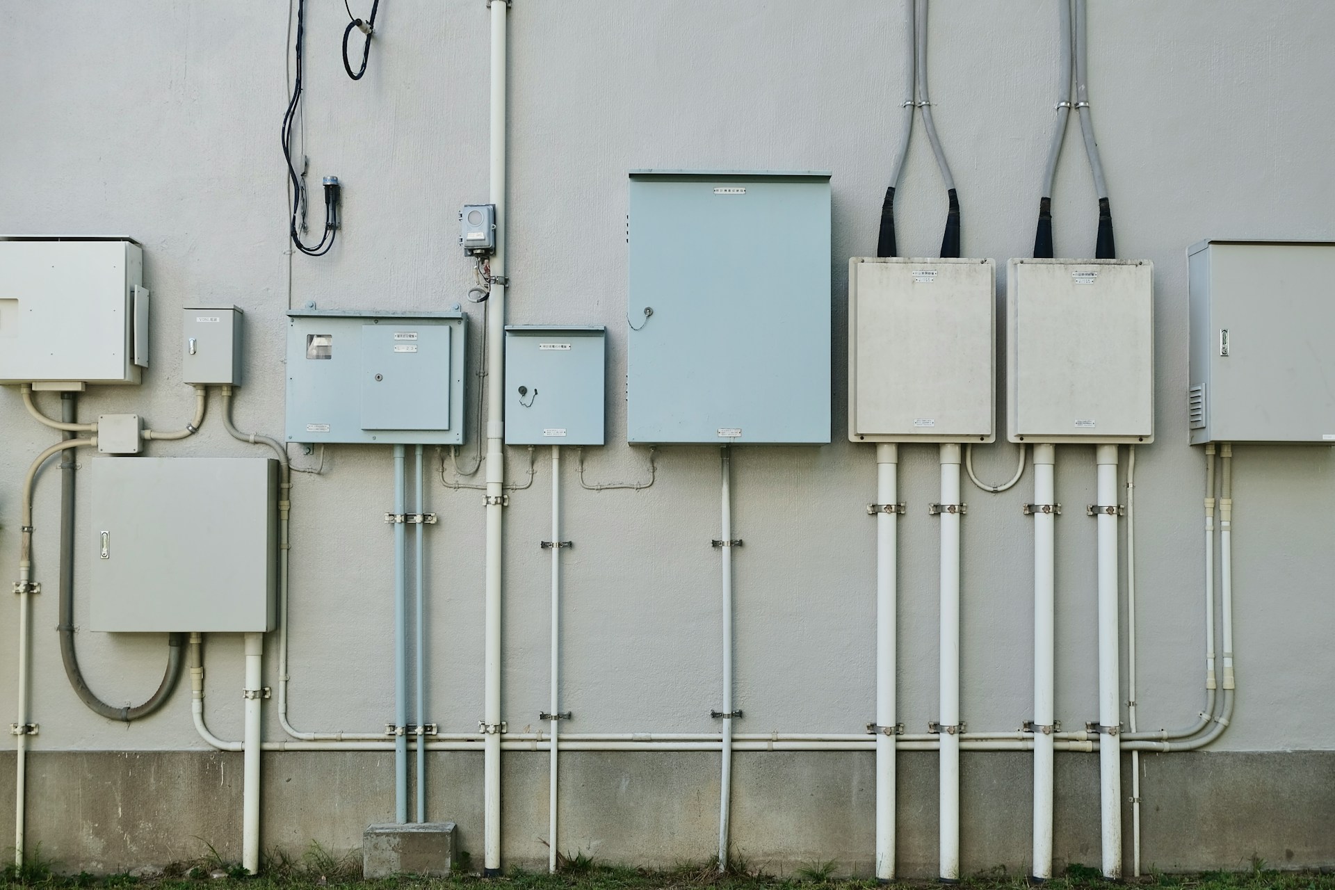
Image disclaimer: For identification and illustration only. It may show a product by another manufacturer and may not depict the exact item described; it is not a statement of any product’s quality, approval or performance. Third-party image and trademark rights belong to their owners. See full notice.
What Is It?
A Junction Box (also called a connection box or distribution box) is an enclosure used to protect and organise electrical connections, splices, and terminations in AGL power and control circuits. In airfield ground lighting systems, junction boxes are critical for:
- Housing cable joints and splices for primary and secondary AGL cables
- Providing termination points for isolating transformers and light fixtures
- Enabling branch circuits and tap connections in the series loop
- Offering a protected interface for testing, maintenance, and troubleshooting
Junction boxes are available in various sizes, materials, and ingress protection ratings to suit different installation environments — from above-ground equipment shelters to underground manholes and direct burial applications.
Purpose & Function
The junction box's purpose is to give the many cable joints, splices, and taps in an AGL circuit a protected, accessible home rather than leaving them exposed underground or inside conduit where a fault could go undetected and unreachable. Because AGL series circuits run for kilometres and connect to hundreds of individual isolating transformers, the connections between primary cable, transformer, and fixture are inevitable — the junction box's sealed, strain-relieved enclosure is what keeps those connections from becoming the weak point in an otherwise reliable circuit, protecting them from moisture ingress and mechanical damage while still allowing a technician to open the box, test the joint, and re-seal it during maintenance or troubleshooting.
Where Is It Used?
Junction boxes are deployed throughout the AGL infrastructure, including:
- Runway and Taxiway Lighting Circuits: At the interface between primary cables and isolating transformers, and between transformers and fixtures.
- Power Distribution Systems: In CCR rooms and substations to distribute power to multiple circuits.
- Control and Monitoring Networks: In ALCMS cabinets and remote I/O panels for signal and communication wiring.
- Underground Networks: In manholes and handholes for cable splices and branch connections.
- Equipment Shelters: Inside electrical rooms to terminate incoming and outgoing cables.
Installation & Location
Junction boxes are installed wherever cables need to be spliced, tapped, or transitioned along the AGL network — between primary cable and isolating transformer, between transformer and fixture, in manholes and handholes along underground runs, and inside CCR rooms and equipment shelters to terminate incoming and outgoing circuits. Field-buried boxes are set in a handhole or pit at a depth consistent with the surrounding cable trench, with gland entries sealed against water ingress and enough internal space to make and insulate all splices without crowding. Indoor units are wall- or frame-mounted at a height and position that keeps terminations accessible, with the box location chosen so cable runs on either side stay within a straight, well-supported path rather than adding unnecessary bends or slack.
How Does It Work?
A junction box provides a safe and accessible enclosure for electrical connections. Cables enter through cable glands or conduit entries and are terminated inside using terminal blocks, splice connectors, or direct soldering. The box is designed to:
- Protect connections from moisture, dust, and mechanical damage (IP rated).
- Organise wiring with sufficient space for cable bending and labelling.
- Allow access for routine inspection, testing, and maintenance via removable covers.
- Provide strain relief through secure cable entry points, preventing pull-out forces from damaging connections.
In AGL series circuits, junction boxes are often used to splice the loop conductor through in series to successive isolating transformers, or to tap off the loop for a local fixture connection.
System Architecture & Control Logic
A junction box has no control logic — it is a passive electrical node whose only architectural role is to preserve continuity of the circuit passing through it while providing a sealed, accessible tap-off point. In an AGL series circuit, the loop conductor typically runs straight through the box, entering and leaving through separate glanded ports, while a spliced tap inside feeds the isolating transformer or fixture local to that box; this means a fault at the junction box (a failed seal allowing moisture ingress, for example) shows up to the CCR as a loop-impedance anomaly rather than as a report from the box itself, since the box has no way to communicate its own condition. Detecting a faulty junction box is therefore a matter of loop-level fault indication from the CCR narrowing the search, followed by physical inspection of the boxes on that loop — the box's role in the architecture is purely to be found and opened, not to report.
Loop Tap-Off & Continuity
The junction box splices into the series loop without breaking it — the loop conductor passes straight through while a sealed tap feeds the local fixture circuit.
Series Loop In
From upstream fixture / CCR
Junction Box
Splice / termination, IP66+ sealed
Loop Continues
To next fixture / transformer
Local Tap-Off
Strain-relieved cable entry
Isolating Transformer / Fixture
Physical Construction
The enclosure body is moulded or cast in one of several materials depending on where it sits in the field — UV-stabilised thermoplastic (polycarbonate or polyamide) for lightweight above-ground boxes, cast aluminium or stainless steel for heavier-duty or corrosive environments, and glass-reinforced polyester (GRP) where chemical resistance is a priority — each finished to achieve the box's rated ingress and impact protection. A gasketed lid, secured with captive stainless-steel screws or a quarter-turn latch, seals the enclosure against water and dust while remaining quick to open for cable work. Cable entries are formed as knockouts or pre-drilled and threaded holes sized to metric (M20–M63) or imperial (PG9–PG48) glands, with blanking plugs fitted to any entries left unused so the enclosure's IP rating isn't compromised. Internally, a mounting plate or DIN rail carries terminal blocks, tap-off connectors, or splice kits, and buried boxes sit on a bed of compacted stone or sand with a surrounding drainage layer so water doesn't pool against the enclosure or its cable glands.
Technical Parameters
| Parameter | Typical Value |
|---|---|
| Material | Thermoplastic (PC, PA), cast aluminium, stainless steel, or GRP |
| Ingress Protection | IP66, IP67, IP68 (depending on application) |
| Impact Rating | IK07 to IK10 (mechanical protection) |
| Temperature Range | -40°C to +85°C (depending on material) |
| Dimensions | Various sizes (e.g., 100x100x60mm to 400x300x150mm) |
| Number of Cable Entries | 2 to 12+ (with knockouts or pre-drilled) |
| Cable Entry Size | PG9 to PG48, M20 to M63 metric, or custom |
| Mounting Type | Surface mount, flush mount, or pole mount |
| Colour | Grey, black, or orange (airfield-specific) |
| Standards Compliance | IEC 60529, UL 50E, BS EN 62208 |
Applicable Standards
FAA AC 150/5345‑42
Specification for Airport Light Bases, Transformer Housings, Junction Boxes, and Accessories
IEC 60529
Degrees of protection provided by enclosures (IP Code)
UL 50E
Enclosures for electrical equipment (USA)
BS EN 62208
Empty enclosures for low-voltage switchgear and controlgear
Installation Requirements
Splice Point Positioning
SiteInstall the box wherever cables need to be spliced, tapped, or transitioned — between primary cable and isolating transformer, between transformer and fixture, in manholes and handholes along runs, or at CCR room terminations.
Handhole/Pit Depth Setting
CivilSet field-buried boxes in a handhole or pit at a depth consistent with the surrounding cable trench.
Gland Entry Sealing
ElectricalSeal gland entries against water ingress, sized for the number and gauge of incoming and outgoing cables.
Splice Space Allowance
MechanicalSize and position the box for enough internal space to make and insulate all splices without crowding.
Indoor Mounting Height
MechanicalWall- or frame-mount indoor units at a height and position that keeps terminations accessible.
Cable Route Straightness Check
DocumentationConfirm cable runs on either side stay within a straight, well-supported path rather than adding unnecessary bends or slack.
Pre-Energisation Sign-off
DocumentationRecord box position, cable route, and gland seal details as-built before backfill or panel closure.
Testing & Commissioning
Insulation Resistance (Megger) Test
Pre-EnergisationMegger-test all circuits terminated in the box before backfill or final closure, confirming insulation resistance clears the acceptable minimum.
Cable Entry Seal & Gland Torque Check
Pre-EnergisationConfirm each cable gland is correctly sized, sealed, and torqued to the manufacturer's specification to maintain the box's rated ingress protection.
Loop Tap-Off Continuity Test
EnergisationVerify series loop continuity through the box's tap-off terminations, confirming the splice has not introduced added resistance into the circuit.
Terminal & Connector Torque Verification
EnergisationCheck and re-torque all terminal block or connector fixings to specification, a common source of intermittent faults if left loose.
Ingress Protection (IP) Verification
Final AcceptanceConfirm the closed enclosure meets its rated IP66/IP67/IP68 ingress protection class, checking lid gaskets and unused knockouts are properly sealed.
Enclosure & Mounting Verification
Final AcceptanceCheck the enclosure is correctly mounted (surface, flush, or pole) and that impact rating (IK07–IK10) is appropriate for its location and exposure.
Documentation & As-Built Sign-off
Final AcceptanceRecord insulation, continuity, and IP verification results alongside as-built box position and circuit schedule in the commissioning dossier for handover.
Inspection & Maintenance
Cable Gland Seal Check
AnnualInspect cable glands for degraded sealing that could allow water ingress into the box.
Internal Connection Inspection
AnnualCheck internal terminals and connections for corrosion or looseness.
Thermal Check
Semi-annualLook for discolouration or heat damage at connections, a sign of poor ventilation or a developing fault.
Enclosure Condition Check
AnnualInspect the box body and lid seal for cracking or degradation.
Common Field Issues
Water Ingress Through Cable Glands
Improperly tightened or damaged cable glands are a primary cause of water ingress, leading to corrosion and short circuits. Regular inspection and replacement of worn glands, along with proper torque application, is essential.
Corrosion of Internal Connections
Moisture and contaminants can cause oxidation of terminal blocks and splice connectors, increasing contact resistance. Using anti-oxidant compounds and sealed terminal blocks mitigates this risk.
Overheating Due to Poor Ventilation
Junction boxes with high-current connections can overheat if not adequately ventilated or if the enclosure is too small. Proper sizing and heat dissipation measures (e.g., larger enclosures, venting) are important for reliability.
Troubleshooting Guide
Moisture or Water Found Inside the Box
High Resistance or Intermittent Connection at a Terminal
Enclosure or Cables Feel Warm to the Touch
Circuit Downstream of the Box Not Working
Failure Modes & Root Causes
Cable Gland or Gasket Failure
Terminal Oxidation
Overheating from Poor Ventilation or Sizing
Loose or Open Splice
Safety & Operational Notes
Circuit Isolation Before Opening
Electrical SafetyDe-energise and lock out the CCR before opening a junction box, then verify zero energy at the terminals before handling cable splices or connections inside it.
Confirm the Correct Box on Multi-Circuit Sites
OperationalWhere several circuits pass through nearby junction boxes, positively identify the correct box before isolating work, since opening the wrong one can leave live conductors exposed while the intended circuit stays dark.
Insulation Test Before Re-Energisation
Electrical SafetyAfter any splice or termination work, megger test the affected circuit before restoring power, since a residual fault at re-energisation can trip the CCR or damage healthy equipment on the same circuit.
PPE & Grounding
Personnel SafetyUse insulated tools and appropriate PPE when working on live-capable connections, and confirm the box and cable shielding are bonded/grounded per the electrical design before reconnecting.
Seal Integrity on Reinstatement
Electrical SafetyRenew gaskets and properly seat cable glands on reassembly, since a junction box's moisture seal is critical to preventing insulation breakdown at the splices it protects.
FOD Control at the Enclosure
OperationalKeep tools, fasteners, and removed gaskets accounted for at all times when the box is open, and secure or remove any loose material before closing it, to prevent foreign object debris on the movement area.
Buried or In-Pavement Boxes
OperationalFollow the aerodrome's permit-to-dig and pit-access procedures where the junction box is buried or set below pavement level, and check for water or debris accumulation before opening it.
Restore to Compliant State
ComplianceDo not leave a junction box with a loose connection, an unsealed gland, or a mis-seated cover after maintenance; verify insulation resistance and secure closure before closing out the work order.
Airport Junction Box
An airport junction box is the sealed enclosure that holds cable joints, splices and terminations in an airfield lighting circuit. It gives a protected point for connecting primary and secondary cables, for branch connections and for testing and fault isolation.
Choose the box by its location, load class, sealing rating, size for the cables and joints it must hold, and the voltage of the circuit. For a box used on approach lighting lines, see the approach light junction box, and for PAPI circuits the PAPI junction box.
Engineering & Expert Notes
A Failed Gland Reads Like a Cable Fault
DiagnosticsMoisture ingress through a degraded cable gland often shows up first as a nuisance insulation resistance fault on that circuit, easily mistaken for a failing cable itself. Check gland condition and re-seal before condemning the cable, since replacing the gland alone frequently resolves it.
Loose Terminations Show Up as Heat Before They Show Up as Faults
PreventiveA loose termination inside a junction box generates localised heating well before it produces an outright open circuit or fault. Where thermal imaging is available, a periodic scan of junction boxes can catch a developing loose connection long before it fails in service.
Don't Mix Incompatible Conductor Materials at a Termination
InstallationTerminating dissimilar conductor materials directly together in a junction box without the correct connector can set up galvanic corrosion at the joint over time, degrading the connection long after installation looked sound. Use connectors rated for the specific material combination present.
Check the Gasket Every Time the Lid Comes Off
DurabilityA gasket that looked fine at the last inspection can take permanent compression set after repeated lid removal and re-torquing, silently reducing the ingress protection rating. Inspect and, where needed, replace the gasket at every entry rather than assuming it's still good from last time.
Unused Cable Entries Need Proper Blanking, Not Tape
InstallationAn unused cable entry sealed with tape or an improvised plug instead of a rated blanking gland is a common, easily missed route for moisture and insect ingress. Verify every entry point on the box, not just the ones with cables currently terminated.
Record Which Box on Which Circuit, Not Just "Junction Box #4"
ProcessOn a site with many similar junction boxes, tie maintenance records to the specific circuit and cable run passing through the box, not just a generic box number. This makes it possible to trace a recurring insulation resistance issue back to a specific run when it resurfaces months later.
Frequently Asked Questions
Short answers about AGL junction boxes: IP ratings, materials, direct-burial use, standards and maintenance.
Q1What is an AGL junction box?
A junction box, also called a connection or distribution box, is an enclosure that protects and organises electrical connections, splices and terminations in AGL power and control circuits.
Q2Why are junction boxes used?
They give the many cable joints, splices and taps in an AGL circuit a protected, accessible home instead of leaving them exposed underground or in conduit, where a fault could go undetected and unreachable.
Q3Where are junction boxes used?
At the interface between primary cables and isolating transformers and between transformers and fixtures on runway and taxiway circuits, and in power distribution systems such as CCR rooms.
Q4How does a junction box work?
Cables enter through glands or conduit entries and are terminated inside using terminal blocks, splice connectors or soldered joints, inside a sealed enclosure.
Q5What materials and IP ratings are typical?
Thermoplastic (PC, PA), cast aluminium, stainless steel or GRP, with IP66, IP67 or IP68 protection depending on the application and impact ratings of IK07-IK10.
Q6What sizes and cable entries are available?
Sizes from about 100x100x60 mm to 400x300x150 mm with 2 to 12 or more entries (PG9-PG48 or M20-M63). Mounting is surface, flush or pole, and colours include grey, black and airfield-specific orange.
Q7Which standards apply?
FAA AC 150/5345-42 (Airport Light Bases, Transformer Housings, Junction Boxes, and Accessories), IEC 60529 (IP code), UL 50E and BS EN 62208.
Q8How often should junction boxes be inspected?
Semi-annually for thermal checks (discolouration or heat damage at connections) and annually for cable gland seals, internal connections and enclosure and lid seal condition.
Q9What if water is found inside a junction box?
An improperly tightened or damaged cable gland has allowed ingress. Check each gland for torque, cracks or missing seals and inspect the lid gasket.
Related Components
Go Beyond the Component. Understand the Complete AGL System.
You have explored the component. Now understand how it works within the complete Airfield Ground Lighting system.
Learn AGL from fundamentals to design, installation, testing, photometry, commissioning, maintenance and troubleshooting through structured technical training at Precision AGL Academy.
Build practical knowledge. Understand the circuit. Read the standards. Troubleshoot with confidence.
Your next step in AGL starts here.
Need expert guidance on junction box selection or installation for your AGL system?
Precision AGL Academy provides advice on enclosure sizing, IP rating, cable entry planning, and environmental protection for airfield junction boxes.
Follow the Academy
Important Notice, Disclaimer & Limitation of Liability
Please read before relying on any content on this page.
- Purpose and intended users. This page on Junction Box is an independent educational and informational reference for competent, suitably trained and authorised airfield ground lighting (AGL) and aerodrome electrical personnel. It is not professional engineering, legal or regulatory advice, and using it does not create any professional or client relationship.
- Safety. Work on series circuits, constant current regulators (CCRs), isolating transformers, cables, connectors and lighting equipment can be fatal. Always apply the aerodrome’s permit-to-work and isolation/LOTO procedures, prove dead, use correctly rated instruments and PPE, and follow the manufacturer’s instructions. Nothing here authorises work on live equipment or the bypassing of any safety device or interlock.
- Aviation operations. Nothing here authorises installation, modification, energisation, adjustment, return to service, a change of operating category (CAT I/II/III), a NOTAM or any aerodrome certification or approval decision. These rest with the aerodrome operator, the air navigation service provider and the competent regulator.
- Specifications, ratings and typical values. Descriptions, parameters, ratings, dimensions, photometric values, wattages, service lives, maintenance tasks and intervals, failure modes, certifications (for example CE, FCC, UL or IEC marks) and part or type designations are general, typical and indicative. They may not match any particular product, make, model or version, and they are not a datasheet, design, specification, selection, sizing, procurement or acceptance criterion. The manufacturer’s current documents, the approved design and the project specification prevail.
- Standards and regulations. References to ICAO, FAA, IEC, IEEE, ISO, BIS, DGCA and other standards are paraphrased summaries for orientation only. They may be incomplete or out of date, and standards are revised from time to time. Consult the current official editions. Following this content does not guarantee compliance with any law, standard or regulatory approval, and the regulator’s requirements always prevail.
- No warranty. Content is provided “as is” and “as available”, without warranty of any kind, express or implied, including accuracy, completeness, currency or fitness for a particular purpose. Real installations differ in design, equipment make and model, age and condition.
- Limitation of liability. To the fullest extent permitted by applicable law, Precision AGL Academy, Precision AGL Solutions and their owners, authors and contributors are not liable for any injury, death, loss, damage, downtime, penalty or regulatory consequence, whether direct or indirect, arising from the use of, reliance on, or inability to use this content. Nothing in this notice excludes or limits any liability that cannot lawfully be excluded or limited.
- Independence, brands and no endorsement. This is an independent publication. It is not affiliated with, sponsored by or endorsed by ICAO, the FAA, the IEC, DGCA, AAI, any airport, regulator, supplier or equipment manufacturer. Third-party names, product designations, standard designations and trademarks (including Megger®, Siemens, Eaton, Crouse-Hinds, ADB SAFEGATE, Fluke, ABB and Honeywell) belong to their respective owners and are used only for identification and description. Mention of a brand, product or supplier is not a recommendation, and we do not sell, supply or quote for any component described.
- Images and third-party content. Images and illustrations are shown to help identify the type of component. They may show products of various manufacturers, may not depict the exact item described, and are not a statement about any product’s quality, approval or performance. Copyright and trademarks in third-party images, logos and photographs belong to their respective owners and are not claimed as ours. If you are a rights holder and want an image removed, replaced or credited, email precisionaglsolutions@gmail.com with the page address and we will act promptly.
- Training and services. Mentions of training, courses, consultation, advice, selection, installation, calibration or other support, including the “Learn…Certify” pathway, describe learning stages and are not an offer, quotation, tender or promise of any result. Contacting us or our replying creates no engagement or duty of care; an engagement exists only under a written agreement. We are not a regulator or certification body, and completing any course or reading this content is not a certification, accreditation or authorisation to work on any aerodrome.
- Copyright, privacy and corrections. © 2026 Precision AGL Academy. All rights reserved. Text, structure, compilations and diagrams may be viewed for personal reference and internal training only; any other copying, republication or commercial use needs our written permission. If you email, telephone or message us, we use your details only to respond and handle your matter, in line with applicable Indian law including the Digital Personal Data Protection Act, 2023; please do not send confidential or security-sensitive information. To display this page your browser requests fonts, icons and images from third-party servers, which receive your IP address and browser details under their own policies. Content is reviewed periodically with no obligation to update. To report an error, safety concern or rights issue, write to precisionaglsolutions@gmail.com.