Mandatory Instruction Sign
A red sign with white text, indicating mandatory instructions that must be followed by pilots and vehicle drivers on the airfield. Commonly used for runway holding positions, ILS critical areas, and no‑entry zones. Provides unambiguous regulatory guidance to ensure safe surface movements.
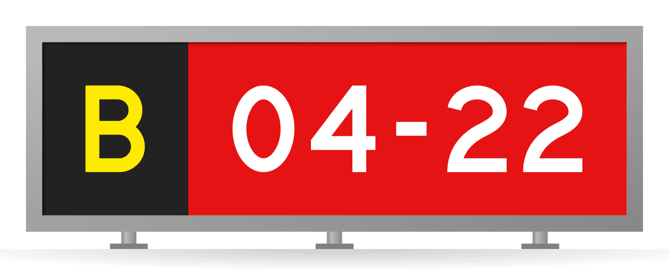
Image disclaimer: For identification and illustration only. It may show a product by another manufacturer and may not depict the exact item described; it is not a statement of any product’s quality, approval or performance. Third-party image and trademark rights belong to their owners. See full notice.
What Is It?
A Mandatory Instruction Sign is a red rectangular sign with white text and symbols that conveys a regulatory instruction that must be obeyed by pilots and vehicle operators. These signs are used at critical locations such as runway holding positions, ILS critical area boundaries, and no‑entry points. The red background and white text are internationally standardized to ensure immediate recognition. The signs may be illuminated (internally or externally) for nighttime visibility and are typically reflective for passive visibility. They are a crucial component of airfield surface movement guidance and control systems.
Purpose & Function
The mandatory instruction sign is the top tier of the airfield's colour-coded signage hierarchy, reserved for the small set of locations where the instruction is not advisory but a regulatory requirement that must be followed regardless of clearance status: holding positions, ILS critical area limits, and no-entry points chief among them. Its purpose is to make that distinction unmistakable at a glance, so that a pilot or driver scanning ahead never has to read the full text of a sign to know whether it demands compliance; the red background alone carries that meaning. This universal colour coding is what allows the sign to function reliably across every airport that follows ICAO or FAA standards, regardless of the specific instruction printed on it.
Where Is It Used?
Installed at runway holding positions (CAT I, II, III), ILS critical area boundaries, stop bars, no‑entry locations, and other points where a mandatory instruction must be conveyed. They are placed on the side of the taxiway or runway, typically at a height of 1.5 to 2 metres above the pavement. They are used at all civil and military airfields that operate under instrument flight rules (IFR) or have complex taxiway layouts.
Installation & Location
Posts are founded at the specific holding position, ILS boundary, stop bar, or no-entry point the sign protects, using the same setback and frangible-mount convention as the underlying location (the CAT I/II/III holding distance, the ILS critical area survey line, or the closed-taxiway boundary as applicable) rather than a single generic rule across the whole category. Because a mandatory instruction sign is paired with a physical control (a stop bar, a pavement marking, a barrier) at nearly every location it serves, its setout is checked against that companion control's position during installation and inspection rather than in isolation. Illuminated panels share cabling with the associated stop bar or holding-position lighting circuit where one exists; standalone locations are fed from the nearest taxiway distribution point.
How Does It Work?
The sign displays a specific instruction using white text on a red background, following ICAO Annex 14 and FAA standards. Common instructions include "RUNWAY" (with a runway designator), "ILS" (critical area), "NO ENTRY", and "STOP" (at holding positions). The sign is either non‑illuminated (using retroreflective sheeting) or illuminated (with internal LED or fluorescent lamps) for nighttime operations. The text and symbols are designed for legibility at a distance of up to 200 metres. The sign is mounted on a frangible or breakaway support to minimize aircraft damage in case of collision.
System Architecture & Control Logic
Mandatory instruction signs carry the same two-model split as other AGL signage, but with a stricter illumination requirement given their safety-critical messages (RUNWAY, ILS, NO ENTRY, STOP). Where illuminated, the sign is wired onto the constant current series circuit serving that holding position or taxiway: an ALCMS selects the required brightness step, the CCR regulates the whole loop to a fixed current, and the sign panel — fed through its own isolating transformer — burns at the same intensity as every other fixture on that loop, with a voltage rise at constant current flagging a loop-level fault rather than a sign-specific one. Because a mandatory instruction sign is often required to be illuminated at night or in low visibility precisely where retroreflective sheeting alone would not be reliable enough, many installations dispense with the passive-only option and default to the illuminated, ALCMS-controlled path even where a simpler information or exit sign nearby might still run on retroreflective sheeting with no electrical control at all.
Illuminated variant: ALCMS → CCR → Loop → Sign Panel. Retroreflective variant: no electrical path at all.
What Each Message Requires
Physical Construction
The panel is an extruded aluminium frame around a translucent acrylic or polycarbonate face with the white-on-red legend applied as a perforated film, internally illuminated by an LED module (or an external floodlight on older installations) rather than left to retroreflective sheeting alone, since a mandatory instruction has to remain legible and unambiguous in every lighting condition rather than only under aircraft landing-light glare. The frame is gasket-sealed to IP65 and mounted on a frangible coupling engineered to a specified shear force, set on a below-grade base plate, so the sign fails safely if struck while still holding rigidly enough in normal service to keep the instruction legible. This construction is the base format that every specific mandatory sign in this library — holding position, no-entry, CAT II/III, ILS critical area — builds its own legend onto.
Technical Parameters
| Parameter | Typical Value |
|---|---|
| Colour | Red background, white text (ICAO / FAA) |
| Dimensions | 1.2 m × 0.6 m (typical) or as per site requirements |
| Text Height | 150–200 mm (depending on viewing distance) |
| Illumination | Internally illuminated (LED) or externally illuminated (floodlight) |
| Retroreflective Class | Class 1 or Class 2 (ASTM D4956) |
| Mounting Height | 1.5–2 m above pavement |
| Frangible Support | Breakaway coupling or frangible post (shear force specified) |
| Protection Class | IP65 (weatherproof) |
| Operating Temperature | -40°C to +60°C |
Electrical Requirements
| Requirement | Typical Value |
|---|---|
| Circuit Type | Series circuit, constant current (CCR fed) — illuminated variant only |
| Rated Series Current | 6.6A (3 to 5-step: 2.8A / 3.4A / 4.1A / 5.2A / 6.6A) |
| Isolation | Via dedicated isolating transformer, not directly connected to series loop |
| Transformer Secondary | Matched to sign wattage; sized to series circuit rating |
| Cable Type | L-824 single-conductor, direct-burial rated, 5kV or 600V per circuit design |
| Connector | L-823 primary connector, submersible-rated splice |
| Insulation Resistance | ≥ 50 MΩ (megger test, cable-to-ground) |
| Earthing/Grounding | Sign body and base can bonded to airfield earth grid |
| Fault Protection | CCR-level ground fault and open-circuit detection |
| Non-Illuminated Variant | No electrical supply required — passive retroreflective panel only |
Photometric Requirements
| Parameter | Typical Value |
|---|---|
| Background Luminance (Red) | ≥ 30 cd/m² average, uniformity ratio ≤ 10:1 (max:min) |
| Legend Luminance (White) | ≥ 150 cd/m² average |
| Legend-to-Background Contrast Ratio | 5:1 to 10:1 per ICAO Annex 14 Attachment A |
| Retroreflective Coefficient (Non-Illuminated Variant) | RA ≥ 50 cd/lux/m² (white), ≥ 15 cd/lux/m² (red) per ASTM D4956 Class 1/2 |
| Chromaticity (Red Background) | Within ICAO Annex 14 aeronautical red boundary (CIE coordinates) |
| Chromaticity (White Legend) | Within ICAO Annex 14 white boundary (CIE coordinates) |
| Viewing Angle | ± 5° horizontal, legible from typical cockpit eye height on approach to the sign |
| Luminance Tolerance | ± 25% of rated value across the panel face |
| Maintenance Factor | ≥ 50% of new-panel luminance before lamp/LED or floodlight/sheeting replacement is due |
| Test Method | Luminance meter/photometer at normal and oblique angles, or retroreflectometer for the non-illuminated variant |
Applicable Standards
ICAO Annex 14
Mandatory instruction sign colours, dimensions, and placement requirements
FAA AC 150/5340-18
Standards for Airport Sign Systems — siting, design, and colour convention for this sign type
FAA AC 150/5345-44
Equipment/fixture specification for the sign unit itself (siting, design and colour are governed by AC 150/5340-18 above)
ASTM D4956
Retroreflective sheeting performance standards
IEC 60598
Luminaire requirements for illuminated signs
Installation Requirements
Setting-Out & Siting Survey
CivilSurvey and mark the sign position from the design/siting drawing before excavation, confirming clearance from the taxiway/runway edge safety area and any frangibility height limit.
Foundation / Base Plate Installation
CivilExcavate and set the base plate or footing to design depth, keeping the finished mount level and within the frangible height limit for the sign's location.
Frangible Mount Fitting
MechanicalFit the frangible post (specified shear force) or breakaway coupling and torque to the specified value, confirming it shears as designed under lateral load and does not bind.
Cable Route & Connector Termination
ElectricalWhere the sign is internally illuminated, lay the duct/cable route to the panel and terminate the L-823 connector per manufacturer procedure, keeping the splice fully submersible-rated before backfill.
Isolating Transformer Matching
ElectricalWhere the sign is internally illuminated, confirm the isolating transformer wattage and ratio match the panel and the series circuit's rated current step before connection.
Panel Legend & Content Setting
QualityBefore the panel is fixed and the position closed out, confirm the regulatory text or symbol on the panel matches the airfield signage schedule for that location, since an incorrect mandatory message can misdirect pilots or vehicle operators.
Retroreflective Sheeting Application
MechanicalApply and inspect the retroreflective sheeting for correct grade, alignment, and freedom from bubbles or edge lifting before the panel is mounted.
Pre-Backfill Sign-off
DocumentationRecord base/footing position, frangible coupling torque, cable route, and panel content as-built before backfill, since these are not inspectable once the site is closed.
Testing & Commissioning
Insulation Resistance (Megger) Test
Pre-EnergisationWhere the sign is internally illuminated, megger-test the isolating transformer and internal wiring before the circuit is energised, confirming insulation resistance clears the acceptable minimum ahead of backfill.
Loop Continuity & Resistance Test
Pre-EnergisationFor an illuminated installation, verify series loop continuity through the sign and record loop resistance, ruling out open circuits or high-resistance splices before first energisation.
Primary/Secondary Voltage Verification
EnergisationWith the CCR energised, confirm secondary voltage at the illuminated sign's L-823 connector matches the transformer's rated ratio at the commissioned current step.
CCR Brightness Step Response
EnergisationCycle the CCR through every intensity step and confirm an illuminated panel responds correctly at each, ruling out a marginal transformer or a loose connection.
Retroreflectivity / Luminance Verification
Final AcceptanceMeasure sheeting retroreflectivity with a retroreflectometer against ICAO/FAA commissioning minimums; where the panel is internally illuminated, also verify luminance and colour uniformity with a luminance meter.
Legend & Content Verification
Final AcceptanceConfirm the regulatory text or symbol on the panel matches the airfield signage schedule for that location, since an incorrect mandatory message can misdirect pilots or vehicle operators.
Frangible Coupling & Mounting Verification
Pre-EnergisationConfirm the frangible coupling, base depth, and panel height meet as-built tolerances before the site is finally backfilled.
Documentation & As-Built Sign-off
Final AcceptanceRecord retroreflectivity/luminance readings, and (where illuminated) insulation, continuity, and voltage readings, alongside as-built position in the commissioning dossier for handover.
Inspection & Maintenance
Retroreflectivity Check
AnnualMeasure sheeting retroreflectivity with a retroreflectometer against ICAO / FAA minimums, and budget for sheeting replacement roughly every 5–7 years.
Illumination System Test
AnnualTest internal LED or fluorescent illumination for uniform, even lighting so the sign remains legible at night, especially ahead of low-visibility seasons.
Frangible Coupling Inspection
AnnualCheck the coupling or post for brittleness or corrosion and replace per manufacturer schedule to preserve breakaway performance on impact.
Seal & Cable Gland Check
AnnualInspect housing seals and cable glands for degradation, since moisture ingress through damaged seals is a leading cause of corrosion and electrical faults.
Sign Face Cleaning
QuarterlyClean dirt, de-icing fluid residue, and rubber deposits off the sign face to keep both reflectivity and legibility within spec.
Insulation Resistance Test
AnnualMegger-test internal wiring and any isolating transformer to confirm insulation resistance stays above minimum, catching moisture ingress early.
Common Field Issues
Retroreflective Sheeting Degradation
UV exposure, weathering, and abrasion from sand or de‑icing chemicals can reduce the reflectivity of the sign. Regular inspection and replacement of sheeting (typically every 5–7 years) is recommended to maintain night visibility.
Internal Illumination Failure
LED modules or fluorescent tubes inside illuminated signs can fail, reducing legibility at night. Regular testing of the illumination system and replacement of failed components is essential.
Frangible Support Fatigue
The frangible coupling or post can become brittle over time due to weather and vibration. Regular inspection and replacement as per manufacturer recommendations are required to ensure breakaway performance.
Moisture Ingress
Water can enter the sign housing through damaged seals or cable glands, causing corrosion and electrical faults. Routine seal checks and the use of desiccants are recommended.
Troubleshooting Guide
Red Background or White Text Unreadable at Night
Illuminated Sign Dark or Flickering
Moisture Ingress at Housing or Cable Gland
Sign Leaning, Loose, or Misaligned
Failure Modes & Root Causes
LED Panel / Internal Light Source Failure
Retroreflective Sheeting Degradation
Frangible Coupling Fatigue / Impact Damage
Loss of Synchronization With Paired Stop Bar / Holding-Position Circuit
Power/Circuit Connector Degradation
Safety & Operational Notes
Circuit Isolation Before Access
Electrical SafetyDe-energise and lock out the feeder circuit at the CCR or panel, then verify zero energy at the base can before opening the housing or handling cable connectors.
Airside Work Coordination
OperationalAny work on or near the movement area requires ATC/airside coordination and a NOTAM where the sign will be dark, obscured, or out of tolerance, with vehicle and personnel movement kept clear of the taxiway or runway strip per the aerodrome's safety management procedures.
Frangibility Not to Be Defeated
MechanicalNever substitute the frangible coupling with a rigid fitting or over-torque it during installation or repair; the coupling must still shear cleanly on aircraft impact to limit damage under the frangibility requirement.
FOD Control at the Base
OperationalKeep tools, fasteners, and removed gaskets accounted for at all times when the base can or housing is open, and secure or remove any loose material before reinstating the sign, to prevent foreign object debris on the movement area.
Insulation Test Before Re-Energisation
Electrical SafetyAfter any cable, connector, or panel work, megger test the affected circuit before restoring power, since a residual fault at re-energisation can trip the feeder circuit or damage healthy units on the same loop.
PPE & Grounding
Personnel SafetyUse insulated tools and appropriate PPE when working on circuit connections, and confirm the sign housing and base can are bonded/grounded per the electrical design before reconnecting the circuit.
Do Not Leave De-Energised During Traffic
OperationalBecause this sign marks a mandatory holding position and protects against runway incursion, never leave it dark or unreadable while traffic is active; if it cannot be restored immediately, close the associated taxiway or coordinate an alternative procedural safeguard with ATC first.
Engineering & Expert Notes
Never Walk Away From a Dark Sign During Active Traffic
OperationalIf power can't be restored immediately, coordinate a procedural stop-bar instruction or ATC safeguard before leaving the site — a dark mandatory sign silently removes the “must stop” cue it exists to give.
Know Which Specific Instruction It's Protecting Before Deciding Urgency
OperationalRed/white signs cover holding positions, ILS critical areas, and no-entry zones alike; identify which one you're looking at first, since a dark no-entry sign and a dark CAT II holding sign follow different escalation paths.
Contrast Fails Before Full Illumination Loss
TroubleshootingPartial LED degradation on a red background reduces white-on-red contrast well before the sign goes fully dark — a sign that's “still lit” can already be below the legibility margin this category depends on.
Treat Coupling Fatigue Here as a Priority Item, Not Routine Maintenance
MechanicalA leaning or misaligned mandatory instruction sign undermines the unambiguous instruction this category exists to give — prioritise coupling replacement accordingly rather than folding it into general sign upkeep.
Retest Sightlines After Any Nearby Pavement Work
InspectionOverlay or reconstruction work near a mandatory sign can change the sightline geometry aircraft use to spot it. Retest visibility from the approach direction, not just the sign's own structural integrity.
Agree the Escalation Path Before the Fault Happens, Not During
OperationalKnow in advance who to call — ATC, duty ops — for an out-of-service mandatory sign. Working that out while the fault is live costs response time this sign category can't spare.
Frequently Asked Questions
Short answers about mandatory instruction signs: colour, messages, siting, power, standards, maintenance and common faults.
Q1What is a mandatory instruction sign?
A mandatory instruction sign is a red rectangular airfield sign with white text and symbols that conveys a regulatory instruction pilots and vehicle operators must obey. It is used at runway holding positions, ILS critical area boundaries and no-entry points, and may be internally illuminated or externally lit for night use, or made passively visible with retroreflective sheeting.
Q2What colour is a mandatory instruction sign and why?
Mandatory instruction signs use white text on a red background. The colour combination is internationally standardised so that a pilot or driver recognises a regulatory, non-advisory instruction at a glance, without needing to read the full legend. Red-background signage is always mandatory, never advisory.
Q3What messages appear on mandatory instruction signs?
The common messages are RUNWAY with a runway designator (holding position: stop and do not cross without ATC clearance), ILS (critical area boundary: stop outside the area whenever the ILS is in use), NO ENTRY (restricted zone: do not proceed under any circumstance) and STOP (stop bar or holding point: stop immediately and contact ATC before proceeding). All four carry the same weight.
Q4Where are mandatory instruction signs installed?
They are placed at runway holding positions (CAT I, II and III), ILS critical area boundaries, stop bars and no-entry locations, on the side of the taxiway or runway at a typical mounting height of 1.5 to 2 metres above the pavement. Setback follows the convention of the location being protected, and setout is checked against the companion stop bar or pavement marking during installation.
Q5Are all mandatory instruction signs illuminated?
No. There are two variants. The illuminated variant uses an internal LED module (or external floodlight on older installations) fed from the airfield lighting circuit. The non-illuminated variant is a passive retroreflective panel with no electrical supply. Illuminated construction is preferred for mandatory messages because the sign must stay legible in every lighting condition, not only under aircraft landing-light glare.
Q6How is an illuminated mandatory instruction sign powered?
It is wired to the constant current series circuit serving that holding position or taxiway, through its own isolating transformer rather than directly on the loop. The Constant Current Regulator (CCR) holds the loop at a fixed current (up to 6.6 A, with steps of 2.8, 3.4, 4.1, 5.2 and 6.6 A), and the ALCMS selects the brightness step, so the sign burns at the same intensity as other fixtures on that loop.
Q7Which standards apply to mandatory instruction signs?
ICAO Annex 14 covers colours, dimensions and placement. FAA AC 150/5340-18 covers siting, design and colour convention for airport sign systems. FAA AC 150/5345-44 is the equipment specification for the sign unit itself. ASTM D4956 sets retroreflective sheeting performance, and IEC 60598 covers luminaire requirements for illuminated signs.
Q8What are the photometric requirements for a mandatory instruction sign?
Typical values are a red background luminance of at least 30 cd/m2 average (uniformity no worse than 10:1) and a white legend luminance of at least 150 cd/m2 average, giving a legend-to-background contrast of 5:1 to 10:1 per ICAO Annex 14 Attachment A. For the non-illuminated variant, the retroreflective coefficient should be at least 50 cd/lux/m2 for white and 15 cd/lux/m2 for red per ASTM D4956 Class 1 or 2. The luminance tolerance is plus or minus 25% across the panel face.
Q9Why is a mandatory instruction sign mounted on a frangible support?
The panel sits on a frangible post or breakaway coupling with a specified shear force so that it shears cleanly if struck by an aircraft, limiting damage. The coupling must never be replaced with a rigid fitting or over-torqued during installation or repair, because that defeats the frangibility requirement.
Q10How often should mandatory instruction signs be inspected and maintained?
Typical intervals are quarterly for cleaning dirt, de-icing residue and rubber deposits off the sign face, and annual for retroreflectivity measurement, illumination testing, frangible coupling inspection, seal and cable gland checks, and insulation resistance (megger) testing. Retroreflective sheeting is usually budgeted for replacement every 5 to 7 years.
Q11What should be done if a mandatory instruction sign is dark or unreadable at night?
Check for supply voltage at the sign connector first, then isolate the LED module, tube or driver, and inspect cable terminations, seals and cable glands for moisture ingress. On a non-illuminated sign, take a reflectivity reading against the ICAO/FAA minimum and replace degraded sheeting. Treat it as high priority: never leave a mandatory sign dark or unreadable while traffic is active. If it cannot be restored immediately, coordinate with ATC on an alternative procedural safeguard or close the associated taxiway.
Related Components
Go Beyond the Component. Understand the Complete AGL System.
You have explored the component. Now understand how it works within the complete Airfield Ground Lighting system.
Learn AGL from fundamentals to design, installation, testing, photometry, commissioning, maintenance and troubleshooting through structured technical training at Precision AGL Academy.
Build practical knowledge. Understand the circuit. Read the standards. Troubleshoot with confidence.
Your next step in AGL starts here.
Need expert advice on mandatory instruction sign selection or placement?
Precision AGL Academy provides guidance on sign design, illumination, and compliance with ICAO and FAA requirements.
Follow the Academy
Important Notice, Disclaimer & Limitation of Liability
Please read before relying on any content on this page.
- Purpose and intended users. This page on Mandatory Instruction Sign is an independent educational and informational reference for competent, suitably trained and authorised airfield ground lighting (AGL) and aerodrome electrical personnel. It is not professional engineering, legal or regulatory advice, and using it does not create any professional or client relationship.
- Safety. Work on series circuits, constant current regulators (CCRs), isolating transformers, cables, connectors and lighting equipment can be fatal. Always apply the aerodrome’s permit-to-work and isolation/LOTO procedures, prove dead, use correctly rated instruments and PPE, and follow the manufacturer’s instructions. Nothing here authorises work on live equipment or the bypassing of any safety device or interlock.
- Aviation operations. Nothing here authorises installation, modification, energisation, adjustment, return to service, a change of operating category (CAT I/II/III), a NOTAM or any aerodrome certification or approval decision. These rest with the aerodrome operator, the air navigation service provider and the competent regulator.
- Specifications, ratings and typical values. Descriptions, parameters, ratings, dimensions, photometric values, wattages, service lives, maintenance tasks and intervals, failure modes, certifications (for example CE, FCC, UL or IEC marks) and part or type designations are general, typical and indicative. They may not match any particular product, make, model or version, and they are not a datasheet, design, specification, selection, sizing, procurement or acceptance criterion. The manufacturer’s current documents, the approved design and the project specification prevail.
- Standards and regulations. References to ICAO, FAA, IEC, IEEE, ISO, BIS, DGCA and other standards are paraphrased summaries for orientation only. They may be incomplete or out of date, and standards are revised from time to time. Consult the current official editions. Following this content does not guarantee compliance with any law, standard or regulatory approval, and the regulator’s requirements always prevail.
- No warranty. Content is provided “as is” and “as available”, without warranty of any kind, express or implied, including accuracy, completeness, currency or fitness for a particular purpose. Real installations differ in design, equipment make and model, age and condition.
- Limitation of liability. To the fullest extent permitted by applicable law, Precision AGL Academy, Precision AGL Solutions and their owners, authors and contributors are not liable for any injury, death, loss, damage, downtime, penalty or regulatory consequence, whether direct or indirect, arising from the use of, reliance on, or inability to use this content. Nothing in this notice excludes or limits any liability that cannot lawfully be excluded or limited.
- Independence, brands and no endorsement. This is an independent publication. It is not affiliated with, sponsored by or endorsed by ICAO, the FAA, the IEC, DGCA, AAI, any airport, regulator, supplier or equipment manufacturer. Third-party names, product designations, standard designations and trademarks (including Megger®, Siemens, Eaton, Crouse-Hinds, ADB SAFEGATE, Fluke, ABB and Honeywell) belong to their respective owners and are used only for identification and description. Mention of a brand, product or supplier is not a recommendation, and we do not sell, supply or quote for any component described.
- Images and third-party content. Images and illustrations are shown to help identify the type of component. They may show products of various manufacturers, may not depict the exact item described, and are not a statement about any product’s quality, approval or performance. Copyright and trademarks in third-party images, logos and photographs belong to their respective owners and are not claimed as ours. If you are a rights holder and want an image removed, replaced or credited, email precisionaglsolutions@gmail.com with the page address and we will act promptly.
- Training and services. Mentions of training, courses, consultation, advice, selection, installation, calibration or other support, including the “Learn…Certify” pathway, describe learning stages and are not an offer, quotation, tender or promise of any result. Contacting us or our replying creates no engagement or duty of care; an engagement exists only under a written agreement. We are not a regulator or certification body, and completing any course or reading this content is not a certification, accreditation or authorisation to work on any aerodrome.
- Copyright, privacy and corrections. © 2026 Precision AGL Academy. All rights reserved. Text, structure, compilations and diagrams may be viewed for personal reference and internal training only; any other copying, republication or commercial use needs our written permission. If you email, telephone or message us, we use your details only to respond and handle your matter, in line with applicable Indian law including the Digital Personal Data Protection Act, 2023; please do not send confidential or security-sensitive information. To display this page your browser requests fonts, icons and images from third-party servers, which receive your IP address and browser details under their own policies. Content is reviewed periodically with no obligation to update. To report an error, safety concern or rights issue, write to precisionaglsolutions@gmail.com.