Marker Beacon
A ground-based radio navigation aid that provides distance‑to‑runway information to aircraft on an Instrument Landing System (ILS) approach. Marker beacons transmit vertical fan‑shaped signals at fixed distances from the runway threshold, enabling pilots to identify key positions (outer, middle, and inner markers) along the final approach path.
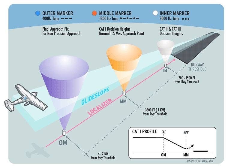
Image disclaimer: For identification and illustration only. It may show a product by another manufacturer and may not depict the exact item described; it is not a statement of any product’s quality, approval or performance. Third-party image and trademark rights belong to their owners. See full notice.
What Is It?
A Marker Beacon is a ground‑based VHF radio transmitter that radiates a narrow, fan‑shaped signal vertically upward. It is used in conjunction with the Instrument Landing System (ILS) to provide distance‑fix information to pilots during the final approach. The system typically consists of three marker beacons located at specific distances from the runway threshold:
- Outer Marker (OM): Located approximately 4–7 nautical miles (7.4–13 km) from the threshold, at or near the glide slope intercept altitude. It identifies the initial approach fix and the final approach segment. The signal is modulated at 400 Hz and produces a continuous series of dashes (— — —) in the cockpit.
- Middle Marker (MM): Located approximately 1.1 km (0.7 miles) from the threshold. It identifies the decision height point for CAT I approaches. The signal is modulated at 1300 Hz and produces alternating dots and dashes (· — · —).
- Inner Marker (IM): Located approximately 300 metres (1,000 ft) from the threshold. It identifies the decision height point for CAT II/III approaches. The signal is modulated at 3000 Hz and produces a continuous series of dots (· · · ·).
Each marker beacon transmits a 75 MHz carrier, which is received by the aircraft’s marker beacon receiver, triggering both an aural tone and a visual light (blue, amber, white) in the cockpit to inform the pilot of the aircraft’s position along the approach.
Purpose & Function
The marker beacon's purpose is to give the pilot a positive, unambiguous confirmation of specific distances along the final approach, independent of the localizer and glide slope signals that provide continuous lateral and vertical guidance. Because each of the three beacons uses a different modulation tone and produces a distinct aural and visual cue in the cockpit, a pilot flying the approach gets a series of confirmed checkpoints, initial approach fix, then decision height for CAT I, then decision height for CAT II/III, without needing to interpret a continuously varying deviation indicator. This distance-fix role is largely what DME now provides on most modern approaches, but where marker beacons remain installed they still serve the same underlying purpose of marking a fixed point along the approach path with a signal the pilot cannot mistake for anything else.
Where Is It Used?
Marker beacons are installed on precision approach runways that support ILS operations. They are used for:
- CAT I Precision Approaches: The outer and middle markers provide critical distance and decision height references.
- CAT II and CAT III Precision Approaches: The middle and inner markers provide enhanced distance and decision height references for low‑visibility operations.
- Military Airfields: Supporting military ILS approaches and training.
- Non‑ILS Approaches: In some cases, marker beacons are also used for localiser‑only or VOR approaches as a distance‑fix aid.
Installation & Location
Each marker sits directly on the extended runway centreline, at the fixed distance from the threshold its role requires — the outer marker roughly 4-7 nm out, the middle marker around 3,500 ft from the threshold, and the inner marker (where fitted) just short of it. The antenna radiates a narrow fan-shaped pattern straight upward, so the site must be clear of overhead obstructions and levelled to keep the beam correctly shaped; a small equipment hut at the base houses the transmitter, monitoring electronics, and standby power supply. Because each marker's exact position defines the distance and decision-height cue it gives the pilot, siting is tied to a precise survey referenced to the runway threshold, with the location fixed on the published approach chart.
How Does It Work?
The marker beacon system operates on a simple but reliable principle:
- Signal Transmission: Each marker beacon transmitter generates a 75 MHz carrier signal that is modulated with a specific audio frequency (400 Hz, 1300 Hz, or 3000 Hz). The signal is radiated vertically upward using a directional antenna that creates a narrow, fan‑shaped pattern (approximately 20° to 40° wide).
- Aircraft Reception: As the aircraft passes over the beacon, the aircraft’s marker beacon receiver detects the 75 MHz signal, demodulates the audio tone, and triggers both an aural tone and a visual indication in the cockpit.
- Visual Indication: The cockpit marker beacon display typically includes three coloured lights: blue (outer), amber (middle), and white (inner). The appropriate light flashes in sync with the received audio tone.
- Distance Fix: The known distances of the markers from the runway threshold provide the pilot with a precise distance‑fix, which is used to confirm the aircraft’s position along the final approach and to verify the decision height.
System Architecture & Control Logic
The marker beacon is one of the simplest transmitting facilities on the airfield and carries a correspondingly thin control loop. The transmitter runs continuously at fixed power and frequency (75 MHz) with a fixed keying pattern for its identity (outer, middle or inner), so there is no dynamic command input to regulate during normal operation. An internal monitor checks transmitted power and modulation depth against tolerance; if either falls out of tolerance, the unit reports a fault — and on more advanced installations may shut down — so that a controller or maintenance system is alerted rather than an aircraft continuing to receive a degraded or false marker indication.
Fixed Oscillator → Keying → Transmitter → Internal Monitor → Fault Reporting
How the Marker Beacon Alerts the Pilot
Ground Transmitter Radiates Signal
75 MHz carrier, fan-shaped pattern beamed vertically upward
Aircraft Passes Overhead
Onboard receiver detects the 75 MHz signal & demodulates the tone
Blue Light — 400 Hz
Flashes in sync with dash tone
Amber Light — 1300 Hz
Flashes in sync with dot/dash tone
White Light — 3000 Hz
Flashes in sync with dot tone (CAT II/III only)
Pilot Confirms Distance Fix
Verifies aircraft position along final approach & decision height
Physical Construction
The transmitter and its monitoring electronics are housed in a weatherproof equipment shelter or rack cabinet near the antenna site, built with dual-redundant, hot-standby transmitter modules so a fault in the active unit triggers an automatic changeover without interrupting the signal. The antenna itself is a fixed, vertically polarised array — typically a set of dipole or Alford-loop elements arranged to produce the directional, fan-shaped radiation pattern that defines the beacon's coverage — mounted on a low, frangible support structure set well clear of the approach or runway centreline so it poses no obstruction hazard. Cabling runs from the shelter to the antenna in a weatherproof feed line, and the whole installation is bonded to a local earthing system for lightning protection. Power comes from the mains supply backed by an uninterruptible supply and standby generator, and a continuous self-monitoring circuit compares transmitted signal parameters against tolerance limits, raising an alarm to the control tower or maintenance system the moment the beacon drifts out of specification.
Technical Parameters
| Parameter | Typical Value |
|---|---|
| Frequency | 75 MHz (VHF) |
| Modulation Frequencies | Outer: 400 Hz, Middle: 1300 Hz, Inner: 3000 Hz |
| Modulation Depth | 95% minimum |
| Antenna Type | Directional, vertically polarised (fan‑shaped pattern) |
| Antenna Pattern | Approx. 20° to 40° horizontal beamwidth |
| Transmitter Power | Typically 1W to 5W (adjustable based on coverage) |
| Coverage | Vertical fan‑shaped, up to approx. 4,000 ft AGL |
| Identification | Outer: dashes (— — —), Middle: dots/dashes (· — · —), Inner: dots (· · · ·) |
| Standby System | Dual redundant (hot standby) for critical installations |
| Monitoring | Continuous self‑monitoring with alarm triggering on failure |
| Power Supply | Mains with UPS and generator backup |
| Protection Class | IP65 / IP67 (weatherproof for outdoor installation) |
Electrical Requirements
| Requirement | Typical Value |
|---|---|
| Primary Supply | Mains AC feed to the equipment shelter/cabinet, backed by UPS and standby generator |
| Transmitter Power Draw | Sized to 1W–5W RF output plus transmitter and monitor overheads |
| Cabling | Dedicated feeder from the airfield distribution point to the equipment cabinet, sized to the equipment's rated load |
| Circuit Protection | Dedicated circuit breaker/isolator at the cabinet distribution point |
| Surge Protection | SPDs fitted at the power and antenna feed entries |
| Insulation Resistance | ≥ 50 MΩ (megger test, cable-to-ground, at commissioning) |
| Earthing/Grounding | Cabinet and antenna structure bonded to the airfield earth grid |
| Fault Protection | Continuous self-monitoring with alarm reporting on power or transmitter fault |
RF Performance Requirements
| Parameter | Typical Value |
|---|---|
| Carrier Frequency | 75 MHz ± 0.005%, per ICAO Annex 10 |
| Modulation | Tone-modulated (400 Hz outer, 1300 Hz middle, 3000 Hz inner marker), keyed per marker type |
| RF Output Power | 1W – 5W, adjustable to achieve the specified coverage pattern |
| Radiation Pattern | Elliptical/fan-shaped vertical pattern per marker type, oriented across the approach path |
| Coverage Dimensions | Sized per ICAO Annex 10 to give the correct on/off indication as the aircraft crosses the marker |
| Identification | Continuous keyed tone; no voice identification required |
| Frequency Stability | Monitored continuously, with alarm on drift outside tolerance |
| Test Method | Flight inspection of coverage pattern and modulation at commissioning and periodic recertification |
Applicable Standards
ICAO Annex 10
Marker beacon frequency, modulation, and performance requirements
FAA Order JO 6770.2B
Maintenance of 75 MHz Fan Marker (FM) facilities — the FAA's ground-equipment maintenance standard for this beacon type
14 CFR § 171.207
U.S. performance requirements for VHF marker beacon facilities, incorporating ICAO Annex 10
RTCA DO-143
Minimum performance standards for airborne 75 MHz marker beacon receiving equipment
Installation Requirements
Precise Distance Survey
SitePosition each marker on the extended runway centreline at the fixed distance its role requires — outer roughly 4–7 nm out, middle around 3,500 ft from the threshold, inner just short of it — tied to a survey referenced to the runway threshold.
Overhead Obstruction Clearance
CivilConfirm the site is clear of overhead obstructions that would distort the narrow, fan-shaped upward beam.
Site Levelling
CivilLevel the antenna site to keep the radiated beam correctly shaped.
Equipment Hut Fit-Out
MechanicalInstall the transmitter, monitoring electronics, and standby power supply in the equipment hut at the antenna base.
Power Supply Connection
ElectricalConnect mains power with UPS and generator backup, matching the arrangement used for other navigation aid installations.
Published Chart Position Record
DocumentationConfirm the fixed location matches what will be published on the approach chart before commissioning.
Pre-Energisation Sign-off
DocumentationRecord the marker's surveyed position and equipment hut fit-out as-built before commissioning.
Testing & Commissioning
RF Power & Frequency Verification
Pre-EnergisationConfirm transmitter output power and the 75 MHz carrier frequency are within tolerance before the beacon is placed into service.
Modulation Depth & Tone Verification
EnergisationVerify modulation depth meets the 95% minimum and confirm the correct tone (400 Hz outer, 1300 Hz middle, or 3000 Hz inner) and Morse identification pattern are transmitted.
Antenna Pattern & Coverage Verification
EnergisationGround-check (or flight-check where required) the fan-shaped vertical radiation pattern and horizontal beamwidth against the design coverage for the beacon's position on the approach.
Standby / Auto-Changeover Test
Final AcceptanceFor dual-redundant hot-standby installations, force a failure of the primary transmitter and confirm automatic changeover to standby occurs without loss of identification.
Continuous Monitoring & Alarm Verification
Final AcceptanceConfirm the self-monitoring system correctly detects a simulated fault condition and raises an alarm to the appropriate control point.
Documentation & As-Built Sign-off
Final AcceptanceRecord RF power, modulation, coverage, and changeover/alarm test results alongside as-built antenna position in the commissioning dossier for handover.
Inspection & Maintenance
Antenna Pattern & Site Survey
AnnualCheck for vegetation growth, new structures, or terrain changes near the site that could distort the fan-shaped antenna pattern.
Modulation Depth Calibration
Semi-annualMeasure and adjust modulation depth to compensate for component ageing, keeping aural and visual indications reliable.
Flight Inspection Coordination
AnnualSchedule flight inspection to verify coverage pattern, modulation, and identifier against certification requirements.
Power Amplifier Health Check
QuarterlyInspect the transmitter power amplifier for thermal stress indicators and verify output power remains within tolerance.
Standby Transmitter Switchover Test
QuarterlyExercise the hot-standby transmitter to confirm automatic switchover works cleanly in the event of a primary PA failure.
Frequency & Interference Check
AnnualVerify the 75 MHz signal against co-channel and adjacent-channel sources to rule out interference from other transmitters.
Antenna & Feeder Inspection
AnnualExamine antenna elements, feed lines, and connectors for corrosion or damage that could degrade radiated pattern.
Common Field Issues
Antenna Pattern Distortion
Vegetation growth, buildings, or terrain changes near the marker beacon site can distort the fan‑shaped antenna pattern, causing uneven coverage or signal nulls. Regular site surveys and pattern checks are recommended.
Modulation Depth Drift
Over time, the modulation depth of the marker beacon signal can drift due to component ageing or environmental factors, reducing the reliability of the aural and visual indications. Periodic calibration and flight inspection are essential.
Power Amplifier Failure
The transmitter power amplifiers are subject to thermal stress and can fail, especially in remote or harsh environments. Regular maintenance and the use of hot‑standby systems are critical to ensure continuous service.
Interference from Adjacent Transmitters
Co‑channel or adjacent‑channel interference from other 75 MHz transmitters can cause false marker indications or missed detection. Proper frequency planning and site coordination are required.
Troubleshooting Guide
Uneven Coverage or Signal Nulls in the Fan Pattern
Weak or Unreliable Aural/Visual Indications
Loss of Service or Reduced Output Power
False Marker Indications or Missed Detections
Failure Modes & Root Causes
Antenna Pattern Distortion
Modulation Drift
Power Amplifier Thermal Failure
Co-Channel Interference
Safety & Operational Notes
De-Energise Before Antenna or RF Work
RF / Electrical SafetyShut down and lock out the transmitter before working on the antenna, feedline, or ground-plane, and treat the antenna as a live RF source whenever the unit is powered.
Lightning & Static Discharge
Electrical SafetyMarker beacon masts and ground planes are lightning-exposed structures; avoid working on the antenna during thunderstorm activity and bond/discharge the mast before handling it.
Off-Airfield Site Access
OperationalOuter and middle marker sites are often located outside the airport perimeter on separate parcels of land; confirm site access arrangements, gate codes, and any landowner or livestock considerations before dispatching a crew.
NOTAM for Approach Fix Outage
OperationalAn out-of-service marker beacon removes a distance-fix cue used during ILS approaches; raise a NOTAM before taking the transmitter down and confirm restoration before cancelling it.
Fall Protection for Mast Work
Personnel SafetyUse appropriate fall-arrest equipment and follow site-specific procedures whenever work requires accessing an elevated antenna mast or support structure.
PPE & Grounding
Personnel SafetyUse insulated tools and confirm the equipment shelter, mast, and ground-plane are bonded/grounded per the electrical design before reconnecting or re-energising the system.
Verify Frequency & Modulation Before Restoration
ComplianceConfirm the 75 MHz carrier and correct modulation tone/keying for the specific marker (OM, MM, or IM) before returning the beacon to service, since an incorrect signature could mislead cockpit indications.
Engineering & Expert Notes
Antenna VSWR Drift Precedes Hard Failure
RFA rising standing wave ratio at the antenna feed is often the first sign of connector corrosion or a cracked radome, well before the transmitter faults or field strength drops enough to notice on approach; log VSWR at each visit rather than only checking on fault reports.
Ground-Plane Bonding Degrades Invisibly
ElectricalCorrosion at ground-plane bonding straps can quietly raise a site's effective ground resistance over years, changing the antenna's radiation pattern without any visible sign at the mast; include a bonding resistance check in the periodic maintenance cycle, not just a visual inspection.
Isolated Mast Sites See Faster Weathering
EnvironmentalOuter and middle marker sites are often unstaffed and away from the main terminal apron, so ice, vegetation encroachment, and animal damage to cabling can go unnoticed for longer than airfield-core equipment; weight inspection intervals accordingly.
Verify Modulation Tone, Not Just Carrier Presence
ComplianceA beacon transmitting on frequency but with a degraded or incorrect modulation tone or keying can still show "on" on basic monitoring while providing an ambiguous or wrong cockpit indication; confirm tone and keying pattern specifically, not just carrier power.
Standby Power Transfer Needs Field Verification
ElectricalWhere the site relies on standby power for continuity during outages, verify the actual transfer under load during a scheduled test rather than trusting a monitoring panel's "standby ready" indication alone.
Confirm Site Access Before Dispatch, Every Time
OperationalBecause outer and middle marker sites can sit on land the airport doesn't directly control, access arrangements, gate codes, or land use can change between visits without airfield-side notice; reconfirm access ahead of dispatch rather than assuming last visit's arrangement still holds.
Frequently Asked Questions
Short answers about marker beacons: types, frequencies, positions, standards, maintenance and common faults.
Q1What is a marker beacon?
A marker beacon is a ground-based VHF radio transmitter that radiates a narrow, fan-shaped signal vertically upward. Used with the Instrument Landing System (ILS), it gives pilots distance-fix information along the final approach.
Q2What are the three types of marker beacon?
The outer marker sits roughly 4 to 7 nautical miles from the threshold, the middle marker about 1.1 km (0.7 miles) from the threshold, and the inner marker about 300 m (1,000 ft) from it. The middle marker marks the CAT I decision height and the inner marker the CAT II/III decision height.
Q3What frequency and tones do marker beacons use?
All marker beacons transmit on a 75 MHz carrier. The outer marker is modulated at 400 Hz (continuous dashes), the middle at 1300 Hz (alternating dots and dashes) and the inner at 3000 Hz (continuous dots).
Q4What do the cockpit marker beacon lights mean?
The receiver gives an aural tone and a light: blue for the outer marker, amber for the middle marker and white for the inner marker. The light flashes in sync with the received tone.
Q5How does a marker beacon work?
The transmitter radiates a modulated 75 MHz signal upward through a directional antenna. As the aircraft passes overhead, its receiver demodulates the tone and triggers the cockpit indication, confirming position along the approach.
Q6Which standards apply to marker beacons?
The main references are ICAO Annex 10, FAA Order JO 6770.2B (maintenance of 75 MHz fan marker facilities), 14 CFR 171.207 and RTCA DO-143 for airborne receivers. Always verify the current edition and your regulator's requirements.
Q7How often should a marker beacon be maintained?
Typical intervals are an annual antenna pattern and site survey, semi-annual modulation depth calibration, annual flight inspection coordination, and quarterly power amplifier checks and standby transmitter switchover tests. Your regulator's programme takes precedence.
Q8What are the common faults on marker beacons?
Common problems are antenna pattern distortion from vegetation or new structures, modulation depth drift, power amplifier failure and interference from adjacent 75 MHz transmitters. Site surveys, calibration and hot-standby transmitters address these.
Related Components
Go Beyond the Component. Understand the Complete AGL System.
You have explored the component. Now understand how it works within the complete Airfield Ground Lighting system.
Learn AGL from fundamentals to design, installation, testing, photometry, commissioning, maintenance and troubleshooting through structured technical training at Precision AGL Academy.
Build practical knowledge. Understand the circuit. Read the standards. Troubleshoot with confidence.
Your next step in AGL starts here.
Need expert guidance on marker beacon selection, installation, or troubleshooting?
Precision AGL Academy provides advice on site planning, signal optimisation, and flight inspection preparation for marker beacon systems.
Follow the Academy
Important Notice, Disclaimer & Limitation of Liability
Please read before relying on any content on this page.
- Purpose and intended users. This page on Marker Beacon is an independent educational and informational reference for competent, suitably trained and authorised airfield ground lighting (AGL) and aerodrome electrical personnel. It is not professional engineering, legal or regulatory advice, and using it does not create any professional or client relationship.
- Safety. Work on series circuits, constant current regulators (CCRs), isolating transformers, cables, connectors and lighting equipment can be fatal. Always apply the aerodrome’s permit-to-work and isolation/LOTO procedures, prove dead, use correctly rated instruments and PPE, and follow the manufacturer’s instructions. Nothing here authorises work on live equipment or the bypassing of any safety device or interlock.
- Aviation operations. Nothing here authorises installation, modification, energisation, adjustment, return to service, a change of operating category (CAT I/II/III), a NOTAM or any aerodrome certification or approval decision. These rest with the aerodrome operator, the air navigation service provider and the competent regulator.
- Specifications, ratings and typical values. Descriptions, parameters, ratings, dimensions, photometric values, wattages, service lives, maintenance tasks and intervals, failure modes, certifications (for example CE, FCC, UL or IEC marks) and part or type designations are general, typical and indicative. They may not match any particular product, make, model or version, and they are not a datasheet, design, specification, selection, sizing, procurement or acceptance criterion. The manufacturer’s current documents, the approved design and the project specification prevail.
- Standards and regulations. References to ICAO, FAA, IEC, IEEE, ISO, BIS, DGCA and other standards are paraphrased summaries for orientation only. They may be incomplete or out of date, and standards are revised from time to time. Consult the current official editions. Following this content does not guarantee compliance with any law, standard or regulatory approval, and the regulator’s requirements always prevail.
- No warranty. Content is provided “as is” and “as available”, without warranty of any kind, express or implied, including accuracy, completeness, currency or fitness for a particular purpose. Real installations differ in design, equipment make and model, age and condition.
- Limitation of liability. To the fullest extent permitted by applicable law, Precision AGL Academy, Precision AGL Solutions and their owners, authors and contributors are not liable for any injury, death, loss, damage, downtime, penalty or regulatory consequence, whether direct or indirect, arising from the use of, reliance on, or inability to use this content. Nothing in this notice excludes or limits any liability that cannot lawfully be excluded or limited.
- Independence, brands and no endorsement. This is an independent publication. It is not affiliated with, sponsored by or endorsed by ICAO, the FAA, the IEC, DGCA, AAI, any airport, regulator, supplier or equipment manufacturer. Third-party names, product designations, standard designations and trademarks (including Megger®, Siemens, Eaton, Crouse-Hinds, ADB SAFEGATE, Fluke, ABB and Honeywell) belong to their respective owners and are used only for identification and description. Mention of a brand, product or supplier is not a recommendation, and we do not sell, supply or quote for any component described.
- Images and third-party content. Images and illustrations are shown to help identify the type of component. They may show products of various manufacturers, may not depict the exact item described, and are not a statement about any product’s quality, approval or performance. Copyright and trademarks in third-party images, logos and photographs belong to their respective owners and are not claimed as ours. If you are a rights holder and want an image removed, replaced or credited, email precisionaglsolutions@gmail.com with the page address and we will act promptly.
- Training and services. Mentions of training, courses, consultation, advice, selection, installation, calibration or other support, including the “Learn…Certify” pathway, describe learning stages and are not an offer, quotation, tender or promise of any result. Contacting us or our replying creates no engagement or duty of care; an engagement exists only under a written agreement. We are not a regulator or certification body, and completing any course or reading this content is not a certification, accreditation or authorisation to work on any aerodrome.
- Copyright, privacy and corrections. © 2026 Precision AGL Academy. All rights reserved. Text, structure, compilations and diagrams may be viewed for personal reference and internal training only; any other copying, republication or commercial use needs our written permission. If you email, telephone or message us, we use your details only to respond and handle your matter, in line with applicable Indian law including the Digital Personal Data Protection Act, 2023; please do not send confidential or security-sensitive information. To display this page your browser requests fonts, icons and images from third-party servers, which receive your IP address and browser details under their own policies. Content is reviewed periodically with no obligation to update. To report an error, safety concern or rights issue, write to precisionaglsolutions@gmail.com.