Mast Obstruction Light
A dedicated aviation warning light for communication masts, utility poles, and tall towers, typically medium or high intensity with red or white output. Engineered to withstand extreme wind loads, ice, and lightning strikes while providing reliable 24/7 obstruction marking for structures often exceeding 150 metres.
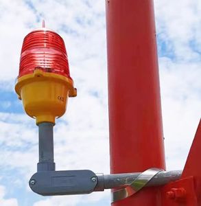
Image disclaimer: For identification and illustration only. It may show a product by another manufacturer and may not depict the exact item described; it is not a statement of any product’s quality, approval or performance. Third-party image and trademark rights belong to their owners. See full notice.
What Is It?
A Mast Obstruction Light is an aviation warning light installed on communication masts (radio, TV, microwave), utility towers, and similar tall lattice structures. These lights are critical for collision avoidance, especially for structures exceeding 150 metres (500 feet) AGL. They typically feature medium‑intensity red (steady or flashing) lights for nighttime and low‑visibility conditions, and high‑intensity white flashing lights for daytime use on taller masts. The lights are mounted at the top and, on taller structures, at intermediate levels set per height-based spacing tables (often cited as roughly every 45 metres, though the exact interval depends on total structure height) to clearly delineate the structure's height and shape. They are designed to withstand extreme weather, ice loading, and lightning strikes, with robust mounting and electrical protection.
Purpose & Function
Mast lighting exists to protect against collision with structures that are frequently among the tallest fixed obstacles in a region — communication and broadcast masts often exceed 150 metres — while presenting an extremely thin, hard-to-see lattice profile against open sky. The dual-mode approach of medium-intensity red at night and high-intensity white flashing by day serves distinct purposes for each condition: red at night provides sufficient warning without excessive glare or light pollution, while high-intensity white is needed during daytime because a red light of ordinary intensity is easily lost against a bright sky background. Marking multiple levels along the mast's height, not just the top, exists because tall masts are frequently guyed structures with a slender profile for their full height, so a pilot needs the intermediate lights to correctly judge where the structure — and any supporting guy wires — actually extends, not just where it ends.
Where Is It Used?
Installed on communication masts (broadcast, cellular, microwave), utility transmission towers, meteorological masts, and any tall lattice structure that requires obstruction lighting under the applicable national aviation authority's rules — in the US, generally any structure exceeding 61 m (200 ft) AGL, or lower where FAA determination requires it near flight paths. 45 m (150 ft) AGL is a separate, lower threshold: above it, the FAA specifies medium‑intensity flashing red (L‑864) rather than low‑intensity steady‑burning (L‑810) lighting. Used extensively in telecommunications, broadcasting, and energy sectors. Multiple lights are installed at the top and, on taller structures, at intermediate levels set per the applicable height-based spacing table (commonly cited as roughly every 45 m, though exact spacing depends on total structure height) to provide a clear outline. The lights must be visible from all directions, requiring omnidirectional or 360° coverage with specific beam patterns.
Installation & Location
Fixtures are installed at the mast top and at intermediate levels at the specified vertical spacing, mounted on brackets that clear the mast's own lattice members, guy wire attachment points, and any antennas so the light is visible from all directions without being shadowed by the structure it's marking. Mounting hardware is specified for the ice loading, wind-induced vibration, and lightning exposure typical of tall guyed structures, with bonding and grounding integrated into the mast's own lightning protection system. Access for installation and maintenance is typically via the mast's climbing facility or a maintenance hoist, since intermediate lights on a very tall mast are not otherwise reachable. Power and control cabling is run down the mast in a protected conduit or cable tray to a base-mounted controller, with each level often individually monitored given the difficulty of visually inspecting lights partway up a tall structure.
How Does It Work?
Each mast obstruction light is powered from a dedicated supply—either direct AC (230V) or via a low‑voltage transformer. The light source is typically a high‑intensity LED array or a xenon flashtube, with red or white output. For masts over 150m, the system often combines high‑intensity white flashing (day) and medium‑intensity red flashing or steady (night) using a photocell to switch modes. The lights are controlled by an integral controller or a remote monitoring system. The housing is constructed from lightweight yet strong materials (aluminium alloy, stainless steel) with IP66/IP67 protection, anti‑icing features, and surge protection to withstand lightning strikes.
System Architecture & Control Logic
A mast's lighting is coordinated by a single integral controller (or remote monitoring system) that reads one photocell and applies the resulting day/night mode across every light level on the structure at once — so the top-of-mast high-intensity fixture and each ~45m intermediate red light switch mode together, even though they present at different intensities. Each level is typically wired back to the same controller and power distribution point rather than looping current from one fixture to the next, so a failure at one intermediate level doesn't take out the lights above or below it on the structure. The same controller also manages the surge protection and anti-icing power drawn by the housings, since a lightning strike or ice buildup is a structure-wide risk rather than a single-fixture one. Where a remote monitoring link is present, faults at any level are reported upstream for maintenance visibility, but — consistent with the other independently-powered obstruction lights on this site — the local day/night switching logic keeps running even if that reporting connection drops.
Dedicated Power Supply → Integral Controller / RMS (photocell input) → Distribution to Every Level
Lighting the Full Height of the Mast
Top of Mast
High-intensity white flash by day, red steady/flash by night — the primary warning point, switched by photocell.
Intermediate Level (~45m below)
Medium-intensity red light outlines the mast's mid-height to approaching aircraft.
Intermediate Level (~90m below)
Repeats every ~45m up the structure, so very tall masts carry several intermediate lights.
Unlike a single-point warning light, the mast's job is to trace the whole shape of a tall lattice structure for an approaching aircraft — each light gives 360° omnidirectional coverage, and the housings add ice-resistant and lightning-protected construction the shorter fixtures on this site don't need.
Physical Construction
The lantern head is built around a die-cast or extruded aluminium housing, anodised or powder-coated to resist UV degradation, salt spray, and industrial pollutants encountered on mast and tower sites. The LED array or xenon flashtube sits behind a moulded polycarbonate or acrylic dome lens, engineered with internal prismatic ribbing to distribute light evenly across the full 360° horizontal arc; the lens-to-housing joint is gasket-sealed to achieve an IP66/IP67 rating, and many units include an internal heater element or hydrophobic coating to shed ice and prevent lens fogging. The housing mounts to the mast structure via a galvanised steel bracket or side-arm, bolted directly to the lattice or pole face and rated to withstand the wind loading and vibration typical of tall, slender structures; units at intermediate levels use standardised clamp fittings so they can be positioned at the required 45-metre intervals without site-specific fabrication. Internal driver and control electronics are potted or conformal-coated and housed in a separate compartment isolated from the optical chamber, with surge arrestors and lightning protection bonded to the structure's earthing system, and all external hardware is stainless steel or hot-dip galvanised to prevent corrosion over the structure's service life.
Technical Parameters
| Parameter | Typical Value |
|---|---|
| Light Source | LED array or xenon flashtube (150W–400W) |
| Colour | Red (night), White (day), or Red/White combination |
| Intensity (Day) | Up to 200,000 cd (white flash) |
| Intensity (Night) | ~2,000 cd (red steady/flash) |
| Flash Pattern | 20–40 flashes per minute (synchronized optional) |
| Mounting Height | Top of mast, plus intermediate levels (every 45m) |
| Beam Coverage | Omnidirectional (360° horizontal) |
| Protection Class | IP66 / IP67, ice‑resistant, lightning‑protected |
| Power Supply | 230V AC or 24V DC (with converter) |
Electrical Requirements
| Requirement | Typical Value |
|---|---|
| Circuit Type | Dedicated mains-fed circuit, independent of the airfield series lighting circuit |
| Supply Voltage | 230V AC or 24V DC (with converter) |
| Cable Type | Ice-resistant, lightning-protected cable routed up the mast to the top and intermediate-level units |
| Control Input | Synchronised flash control wiring between mast levels where fitted |
| Surge Protection | Surge protective devices at each level given the mast's exposed height |
| Insulation Resistance | ≥ 50 MΩ (megger test, cable-to-ground) |
| Earthing/Grounding | Fixture body bonded to the mast structure's earth and lightning protection system at each mounting level |
| Fault Protection | Lamp/LED failure detection and loss-of-sync alarm where units are synchronised |
Photometric Requirements
| Parameter | Typical Value |
|---|---|
| Luminous Intensity (Day) | 2,000 – 20,000 cd (white), where day marking is required |
| Luminous Intensity (Night) | 32 – 2,000 cd (red), per ICAO Annex 14 / FAA AC 70/7460-1 by mast height and level |
| Flash Rate | 20–40 flashes per minute where flashing units are fitted, synchronised between mast levels |
| Beam Pattern | Omnidirectional (360° horizontal coverage) at each mounting level |
| Chromaticity | Red (night) or White (day) within ICAO Annex 14 colour boundaries |
| Level-to-Level Synchronisation | Common flash timing between top and intermediate levels where fitted |
| Ice/Weather Tolerance | Optical output maintained under icing conditions typical of exposed mast heights |
| Test Method | Photometric verification per level at commissioning, with periodic intensity checks |
Applicable Standards
ICAO Annex 14
Obstruction lighting for masts and towers
FAA AC 70/7460-1
Obstruction marking and lighting for tall structures
FAA AC 150/5345-43
Specification for obstruction lighting equipment
FAA Engineering Brief #67
Light Sources Other Than Incandescent and Xenon for Airport and Obstruction Lighting Fixtures — LED equipment requirements
Installation Requirements
Intermediate-Level Positioning
CivilConfirm top-of-mast and intermediate-level lights are positioned at the design 45-metre intervals using standardised clamp fittings, so the full lattice structure is traced for approaching aircraft.
Bracket/Side-Arm Fixing
MechanicalBolt the galvanised steel bracket or side-arm directly to the lattice or pole face per the fixing schedule, rated for the wind loading and vibration typical of tall, slender structures.
Lightning Protection Bonding
ElectricalBond surge arrestors and the lantern housing to the structure's earthing system, since mast-top locations are highly exposed to lightning strikes.
Supply Termination
ElectricalTerminate the 230V AC or 24V DC supply at each lantern, confirming the converter (where fitted) is correctly rated before energisation.
Lens-to-Housing Seal Check
MechanicalConfirm the gasket at the lens-to-housing joint seats correctly to achieve the rated IP66/IP67 protection, and check the heater element or hydrophobic coating is functional for ice resistance.
Day/Night Mode Configuration
ConfigurationConfigure the photocell or control logic so the fixture switches correctly between the high-intensity white day flash and the reduced-intensity red night mode.
Pre-Energisation Sign-off
DocumentationRecord fixture positions, bracket fixing, bonding, and cable termination as-built before the mast is signed off and climbing access is closed out.
Testing & Commissioning
Insulation Resistance Test
Pre-EnergisationMegger-test the supply cable and transformer (where fitted) at each mounting level before energisation, confirming insulation resistance clears the acceptable minimum.
Grounding & Surge Arrester Continuity Check
Pre-EnergisationVerify the fixture's grounding connection and any surge arrester are correctly bonded to the mast's lightning protection system before energisation.
Photocell Threshold Calibration
EnergisationCalibrate the day/night switching threshold against a reference light meter so the top-of-mast and every intermediate-level light switch mode together.
High-Intensity / Medium-Intensity Mode Switching Verification
EnergisationFor masts over 150m, confirm the top-of-mast fixture correctly switches between high-intensity white flashing (day) and red flashing or steady-burning (night).
Multi-Level Flash Synchronisation Test
EnergisationWith every level energised, confirm the top and each intermediate-level light switch mode and flash together, tracing the mast's full height as one coherent signal.
Photometric Intensity Test
Final AcceptanceMeasure light output at each mounting level with a calibrated photometer against ICAO/FAA thresholds for the applicable intensity class.
Mounting Hardware & Ice-Loading Tolerance Check
Final AcceptanceVerify mounting brackets clear the mast's lattice members, guy wire attachment points, and antennas, and are rated for the site's ice-loading and wind conditions.
Documentation & As-Built Sign-off
Final AcceptanceRecord insulation, grounding, threshold calibration, and photometric readings alongside as-built level positions in the commissioning dossier for handover.
Inspection & Maintenance
Grounding & Surge Arrester Check
AnnualTest grounding continuity and inspect surge arresters, since masts are prime lightning targets and repeated strikes can degrade the light's electronics.
Mounting Hardware & Vibration Check
AnnualInspect brackets, solder joints, and lock-wired connections for wind-induced vibration fatigue and re-secure any loosened hardware.
Ice & Coating Inspection
SeasonalCheck anti-icing coatings and, where safe, remove ice buildup on the housing and brackets before it causes mechanical stress or obscures the beam.
Photometric Intensity Check
AnnualVerify beam intensity and colour against ICAO / FAA obstruction lighting thresholds using a calibrated photometer.
Power Supply & Cable Inspection
AnnualCheck power cables and connections for chafing or corrosion from constant sway and wind exposure at height.
Lens & Housing Cleaning
Semi-annualClean the lens and housing of dust, salt spray, or bird debris to maintain full light output and colour fidelity.
Common Field Issues
Lightning Damage
Masts are prime lightning targets. Surge protection and proper grounding are critical. Repeated lightning strikes can damage the light's electronics and power supply. Use of heavy‑duty surge arresters and regular inspection of grounding systems is mandatory.
Ice and Wind Loading
Ice accumulation on the light housing and mounting brackets can cause mechanical failure. Anti‑icing coatings and robust mounting hardware are essential. Regular visual inspection and removal of ice buildup (if safe) is recommended.
Vibration Fatigue
Masts experience constant wind‑induced vibration, which can cause solder joint fatigue and connection loosening. Use of vibration‑resistant mounting and lock‑wired connections can extend service life.
Troubleshooting Guide
Single Level Dark, Rest of Mast Normal
Entire Mast Lighting System Dark
Lights Stuck in Wrong Day/Night Mode
Repeated Lightning-Related Failures
Ice Buildup Blocking Output or Anti-Icing Failure
Intermittent Flicker or Connection Loss
Failure Modes & Root Causes
Single-Level Feed Fault
Integral Controller Failure
Surge Arrester / Grounding Degradation
Ice Accumulation / Anti-Icing Heater Failure
Vibration-Induced Connection Fatigue
Safety & Operational Notes
Mast Climbing Certification
Fall ProtectionOnly climb with current tower-climbing certification and fall-arrest equipment rated for lattice-mast structures; follow the mast owner's permit-to-work before ascending.
Lightning & Grounding
Electrical SafetyCommunication and utility masts are frequent lightning targets; confirm grounding/bonding is intact before work and never climb during an active storm.
Co-Located RF / EMF Exposure
Personnel SafetyCheck for co-located radio, TV, or microwave antennas before climbing; RF exposure near active transmitters may require power-down coordination with the antenna owner or use of RF-monitoring PPE.
Electrical Isolation
Electrical SafetyLock out the fixture supply at the base station and verify zero energy before opening the housing at height.
Ice-Fall Hazard
OperationalBarricade the ground area below during winter maintenance; accumulated ice shedding from the mast or fixture housing is a falling-object hazard to personnel and equipment at the base.
PPE
Personnel SafetyWear full climbing and fall-protection PPE, insulated tools, and RF-exposure PPE where co-located transmitters are present.
Restore to Compliant State
ComplianceVerify intensity and mode (day/night) at each mounted level before closing out the work and notifying the aviation authority the mast is back in compliance.
Engineering & Expert Notes
Ice Loading Changes the Mounting Hardware Failure Mode
MechanicalOn lattice masts in icing climates, accumulated ice adds both static load and impact loading as it sheds unevenly, which can loosen or fatigue mounting hardware faster than the vibration alone would predict. Weight the mounting hardware inspection interval toward the site's actual icing history rather than a generic vibration-based schedule.
Grounding Continuity Degrades Silently Between Strikes
ElectricalA communications or utility mast is a natural lightning attachment point, and a grounding or surge-arrester connection can lose continuity from corrosion or a loosened bond without any visible sign until the next strike passes fault current through equipment it should have bypassed. Test grounding and surge-arrester continuity with a meter on schedule, not just visually.
Multi-Level Synchronisation Faults Are Easy to Miss From the Base
DiagnosticsWith lights at the top and multiple intermediate levels needing synchronised flashing, a single level drifting out of sync can be very hard to spot by eye from ground level, especially in daylight. Verify multi-level flash synchronisation with test equipment rather than relying on a visual check, particularly on masts too tall to observe all levels clearly at once.
Day/Night Mode Switching Failure Has Two Very Different Consequences
PhotocellA mast light stuck in high-intensity white daytime mode after dark is disorienting to nearby air traffic and to anyone in the vicinity of the mast at night, while one stuck in medium-intensity night mode during the day under-marks the structure; treat the two failure directions as equally urgent rather than assuming one is more tolerable.
Co-Located RF Equipment Complicates Access Planning
CoordinationCommunication and broadcast masts carry live RF equipment that requires its own isolation or exclusion-zone procedure before lighting personnel climb the structure, distinct from the electrical lockout of the lighting circuit itself. Coordinate with the mast's RF operator on isolation before any climb, not just with the lighting system's own safety procedure.
Side-Arm Fixings See More Load Reversal Than Face-Mounted Fixtures
DesignA light mounted on a side-arm bracket standing off from the lattice face experiences a different, often larger, moment load under wind reversal than a directly face-mounted fixture, which is worth accounting for when specifying bracket fixing hardware rather than treating all mounting positions on a lattice mast as equivalent.
Frequently Asked Questions
Short answers about mast obstruction lights: when they are required, day and night modes, spacing, lightning protection, standards, maintenance and common faults.
Q1What is a mast obstruction light?
A mast obstruction light is an aviation warning light fitted to communication masts (radio, TV, microwave), utility towers and similar tall lattice structures. It typically uses medium-intensity red at night and, on taller masts, high-intensity white flashing by day.
Q2Which masts need obstruction lights?
Requirements are set by each national aviation authority. In the US, generally any structure over 61 m (200 ft) above ground level needs lighting, or lower where an FAA determination requires it near flight paths. Above 45 m, the FAA specifies medium-intensity flashing red rather than low-intensity steady-burning red. Always check your local authority's rules.
Q3What colour and intensity are mast obstruction lights?
Night lighting is red at about 2,000 cd, with the range spanning 32–2,000 cd depending on mast height and level. Day lighting on taller masts is white flashing, up to 200,000 cd for high-intensity units, or 2,000–20,000 cd where medium-intensity day marking is used.
Q4How many lights does a mast need and how are they spaced?
Lights are installed at the top and, on taller masts, at intermediate levels set by height-based spacing tables, often cited as roughly every 45 m though the exact interval depends on total structure height. Each light must be mounted on brackets that clear lattice members, guy wire attachments and antennas so it is visible from all directions.
Q5Do mast obstruction lights flash in sync?
Where flashing units are fitted, the flash rate is 20–40 flashes per minute, synchronised between mast levels through synchronised control wiring. A loss-of-sync alarm flags units that fall out of step.
Q6How are mast obstruction lights protected from lightning?
Masts are prime lightning targets, so each mounting level has the fixture bonded to the mast's earth and lightning protection system, with surge protective devices at every level and lightning-protected cable. Grounding continuity and surge arresters should be tested regularly.
Q7How does ice and wind affect mast obstruction lights?
Ice can load the housing and brackets and obscure the beam, and constant sway causes vibration fatigue and cable chafing. Lights are specified as ice-resistant with anti-icing coatings and robust mounting hardware, and are inspected seasonally for ice and annually for vibration damage.
Q8Which standards apply to mast obstruction lights?
The main references are ICAO Annex 14, FAA AC 70/7460-1, FAA AC 150/5345-43 (obstruction lighting equipment) and FAA Engineering Brief #67 for LED equipment. Always verify the current edition and your national authority's requirements.
Q9How often should mast obstruction lights be maintained?
Typical intervals are seasonal for ice and coating inspection, semi-annual for lens and housing cleaning, and annual for grounding and surge arrester checks, mounting hardware and vibration checks, photometric intensity checks and power supply and cable inspection. Your approved maintenance programme takes precedence.
Q10Why is one level of my mast dark while the rest works?
Typical causes are a failed LED module or flashtube at that level, a blown fuse on its feed, or a severed conductor between the distribution point and that level. Check supply voltage at the fixture, test the controller output to that level and inspect the cable run for damage.
Related Components
Go Beyond the Component. Understand the Complete AGL System.
You have explored the component. Now understand how it works within the complete Airfield Ground Lighting system.
Learn AGL from fundamentals to design, installation, testing, photometry, commissioning, maintenance and troubleshooting through structured technical training at Precision AGL Academy.
Build practical knowledge. Understand the circuit. Read the standards. Troubleshoot with confidence.
Your next step in AGL starts here.
Need expert guidance on mast obstruction light selection or installation?
Precision AGL Academy provides advice on lightning protection, ice loading, and compliance for tall structure obstruction lighting.
Follow the Academy
Important Notice, Disclaimer & Limitation of Liability
Please read before relying on any content on this page.
- Purpose and intended users. This page on Mast Obstruction Light is an independent educational and informational reference for competent, suitably trained and authorised airfield ground lighting (AGL) and aerodrome electrical personnel. It is not professional engineering, legal or regulatory advice, and using it does not create any professional or client relationship.
- Safety. Work on series circuits, constant current regulators (CCRs), isolating transformers, cables, connectors and lighting equipment can be fatal. Always apply the aerodrome’s permit-to-work and isolation/LOTO procedures, prove dead, use correctly rated instruments and PPE, and follow the manufacturer’s instructions. Nothing here authorises work on live equipment or the bypassing of any safety device or interlock.
- Aviation operations. Nothing here authorises installation, modification, energisation, adjustment, return to service, a change of operating category (CAT I/II/III), a NOTAM or any aerodrome certification or approval decision. These rest with the aerodrome operator, the air navigation service provider and the competent regulator.
- Specifications, ratings and typical values. Descriptions, parameters, ratings, dimensions, photometric values, wattages, service lives, maintenance tasks and intervals, failure modes, certifications (for example CE, FCC, UL or IEC marks) and part or type designations are general, typical and indicative. They may not match any particular product, make, model or version, and they are not a datasheet, design, specification, selection, sizing, procurement or acceptance criterion. The manufacturer’s current documents, the approved design and the project specification prevail.
- Standards and regulations. References to ICAO, FAA, IEC, IEEE, ISO, BIS, DGCA and other standards are paraphrased summaries for orientation only. They may be incomplete or out of date, and standards are revised from time to time. Consult the current official editions. Following this content does not guarantee compliance with any law, standard or regulatory approval, and the regulator’s requirements always prevail.
- No warranty. Content is provided “as is” and “as available”, without warranty of any kind, express or implied, including accuracy, completeness, currency or fitness for a particular purpose. Real installations differ in design, equipment make and model, age and condition.
- Limitation of liability. To the fullest extent permitted by applicable law, Precision AGL Academy, Precision AGL Solutions and their owners, authors and contributors are not liable for any injury, death, loss, damage, downtime, penalty or regulatory consequence, whether direct or indirect, arising from the use of, reliance on, or inability to use this content. Nothing in this notice excludes or limits any liability that cannot lawfully be excluded or limited.
- Independence, brands and no endorsement. This is an independent publication. It is not affiliated with, sponsored by or endorsed by ICAO, the FAA, the IEC, DGCA, AAI, any airport, regulator, supplier or equipment manufacturer. Third-party names, product designations, standard designations and trademarks (including Megger®, Siemens, Eaton, Crouse-Hinds, ADB SAFEGATE, Fluke, ABB and Honeywell) belong to their respective owners and are used only for identification and description. Mention of a brand, product or supplier is not a recommendation, and we do not sell, supply or quote for any component described.
- Images and third-party content. Images and illustrations are shown to help identify the type of component. They may show products of various manufacturers, may not depict the exact item described, and are not a statement about any product’s quality, approval or performance. Copyright and trademarks in third-party images, logos and photographs belong to their respective owners and are not claimed as ours. If you are a rights holder and want an image removed, replaced or credited, email precisionaglsolutions@gmail.com with the page address and we will act promptly.
- Training and services. Mentions of training, courses, consultation, advice, selection, installation, calibration or other support, including the “Learn…Certify” pathway, describe learning stages and are not an offer, quotation, tender or promise of any result. Contacting us or our replying creates no engagement or duty of care; an engagement exists only under a written agreement. We are not a regulator or certification body, and completing any course or reading this content is not a certification, accreditation or authorisation to work on any aerodrome.
- Copyright, privacy and corrections. © 2026 Precision AGL Academy. All rights reserved. Text, structure, compilations and diagrams may be viewed for personal reference and internal training only; any other copying, republication or commercial use needs our written permission. If you email, telephone or message us, we use your details only to respond and handle your matter, in line with applicable Indian law including the Digital Personal Data Protection Act, 2023; please do not send confidential or security-sensitive information. To display this page your browser requests fonts, icons and images from third-party servers, which receive your IP address and browser details under their own policies. Content is reviewed periodically with no obligation to update. To report an error, safety concern or rights issue, write to precisionaglsolutions@gmail.com.