Runway Occupancy Sensor
A high‑reliability detection system that monitors runway occupancy status in real time. Providing critical input to Runway Status Light (RWSL) systems, A‑SMGCS, and ATC surveillance, these sensors enable automated conflict detection, runway incursion prevention, and enhanced safety in all visibility conditions.
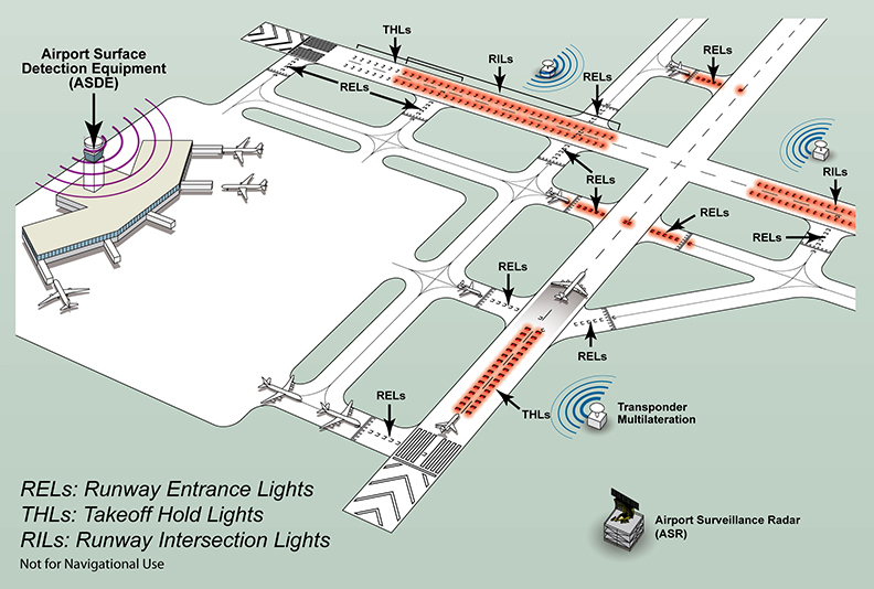
Image disclaimer: For identification and illustration only. It may show a product by another manufacturer and may not depict the exact item described; it is not a statement of any product’s quality, approval or performance. Third-party image and trademark rights belong to their owners. See full notice.
What Is It?
A Runway Occupancy Sensor is a sophisticated detection device that continuously monitors a designated runway zone to determine whether the runway is occupied by an aircraft or vehicle. It is a core component of the Runway Status Light (RWSL) system, providing the real‑time occupancy data required to activate runway entrance lights (RELs), take‑off hold lights (THLs), and runway guard lights. The sensor uses advanced technologies—typically radar, infrared, or inductive loop—to detect targets with high accuracy and reliability, even in adverse weather conditions (fog, rain, snow) and low visibility. Unlike stop bar sensors that detect crossing at a specific point, runway occupancy sensors monitor an entire runway segment (typically several hundred metres) to determine if any target is present on the runway. The sensor's output is fed to the RWSL processing unit, which uses it to determine runway status and control the associated warning lights. By providing precise, continuous occupancy detection, these sensors play a vital role in preventing runway incursions, reducing the risk of runway collisions, and supporting safe, efficient airfield operations.
Purpose & Function
The runway occupancy sensor's purpose is to give the RWSL system a source of truth about the runway that does not depend on a controller noticing and acting on a specific traffic situation. Because RWSL is designed as an automatic layer that operates alongside, not instead of, standard ATC clearances, the sensor has to detect occupancy continuously across the whole monitored runway segment rather than at a single point, so that any aircraft or vehicle present anywhere in the zone is reflected in the light state without a gap in coverage. This continuous, always-on monitoring is what allows REL and THL lights to illuminate automatically the moment a runway becomes occupied, giving pilots and vehicle operators an independent visual cue that functions even if a clearance was misunderstood or a controller's attention was elsewhere.
Where Is It Used?
Runway Occupancy Sensors are deployed at airports requiring enhanced runway safety surveillance, particularly:
- RWSL (Runway Status Light) Systems: As the primary detection input for runway entrance lights (RELs), take‑off hold lights (THLs), and runway guard lights.
- A‑SMGCS (Advanced Surface Movement Guidance and Control Systems): Integrating with A‑SMGCS for comprehensive surface surveillance and conflict detection.
- ATC Towers: Providing controllers with automated runway occupancy status, enhancing situational awareness.
- Airport Operations Centers: Monitoring runway usage for operational planning and resource allocation.
- Low Visibility Operations (CAT II/III): Enabling safe runway occupancy management when RVR is below 400m.
- Busy Hub Airports: Managing high‑density traffic with multiple simultaneous runway movements to prevent conflicts.
- Runway Crossing Points: Monitoring taxiway/runway intersections to prevent incursions.
- Intersecting Runways: Detecting occupancy on intersecting runways to prevent cross‑runway conflicts.
Installation & Location
Radar- and video-based sensors are pole-mounted beside the runway or at intersection entrances, sited and angled to give the required detection zone coverage over the runway surface or the crossing point being monitored, with spacing between poles set by each sensor's field-of-view range. In-pavement variants use inductive loops or magnetometers embedded beneath the surface at the detection points, wired back to a roadside pull box in the same way as other in-ground sensors. Power and data cabling from each sensor or loop is run in duct to a local equipment hut, from which a fibre or copper backbone carries occupancy status to the RWSL logic controller, A-SMGCS processor, or tower display, with sensor siting kept clear of the runway strip's frangibility and obstacle-clearance requirements.
How Does It Work?
The Runway Occupancy Sensor uses a combination of detection technologies to provide continuous, reliable runway occupancy status. Key functional aspects include:
- Detection Technologies: Sensors typically use one or a combination of:
- FMCW Radar (24 GHz or 77 GHz): Detects moving and stationary targets across a wide area, providing range, velocity, and position information, immune to weather and lighting conditions.
- Infrared (thermal or active): Uses thermal signatures or reflected IR to detect targets, effective in darkness, fog, and smoke.
- Inductive Loop Arrays: A series of buried wire loops that detect metallic targets passing over them, providing precise position and direction information.
- Fusion Sensors: Combine multiple technologies (e.g., radar + IR) for improved detection reliability and false‑alarm rejection.
- Coverage Zone: The sensor is positioned to cover a specific runway segment, typically 300‑900 metres or the entire runway length (using multiple sensors). The coverage zone is precisely calibrated to the runway geometry.
- Target Tracking: The sensor processor tracks multiple targets simultaneously, maintaining their position, speed, and heading within the coverage zone.
- Occupancy Determination: The system determines runway occupancy status based on the presence of any tracked target within the runway zone, with configurable dwell times and hysteresis to prevent false triggers from transient targets.
- Output Signal: The sensor provides a clean, isolated output—typically a dry contact, transistor output, or digital message (e.g., via Ethernet/Modbus)—that indicates occupied or clear status. The output is connected to the RWSL logic processor.
- Self‑Diagnostics: The sensor continuously monitors its own health (power, communication, signal quality, internal faults) and provides diagnostic outputs to alert maintenance staff of any degradation or failure.
- Integration: The sensor interfaces with the RWSL processor, A‑SMGCS, and ATC display systems via standard protocols (Ethernet, serial, hardwired).
The sensor is typically mounted on a pole adjacent to the runway, on a dedicated mast, or integrated into existing runway infrastructure (e.g., approach lighting masts). Its position and orientation are carefully engineered to provide optimal coverage while minimising false alarms from adjacent taxiways or apron areas.
System Architecture & Control Logic
The occupancy sensor's control logic sits between the sensing element and the airfield lighting/ATC systems it feeds. The sensor (radar, magnetic loop, or video analytics depending on technology) continuously reports a raw occupied/clear state to a local processing unit, which applies a confirmation and debounce logic — requiring the state to hold for a minimum dwell time — to filter out false triggers before declaring a validated occupancy change. The validated state is passed to the ALCMS, which can automatically illuminate runway status lights, or to ATC's surface surveillance display; the sensor also reports its own health continuously, and a dropout or self-test failure is flagged as a distinct sensor fault so controllers don't mistake an offline sensor for a confirmed-clear runway.
Sensing Element → Processing Unit → Validated State → ALCMS / ATC Display
How the Sensor Determines Occupancy Status
Sensor Monitors Runway Zone
300‑900 m coverage, calibrated to runway geometry
Target Tracking
Position, speed & heading maintained for multiple targets
Occupancy Confirmed
Dwell time & hysteresis applied before status changes
Hysteresis Prevents False Trigger
Brief or borderline detections don't flip the status
Status Sent to RWSL Logic Processor
Occupied / clear — clean isolated output (dry contact, transistor, or Ethernet/Modbus)
Physical Construction
The sensor head is housed in a sealed, weatherproof enclosure — typically die-cast aluminium or glass-reinforced polymer — rated IP65/IP67, with a radome or IR-transparent window covering the antenna or optical aperture to protect it from rain, dust, and de-icing overspray while remaining transparent to the sensing wavelength. Pole-mounted units bolt to an adjustable bracket that allows azimuth and elevation aiming to be set and locked during commissioning, with the bracket itself mounted on a frangible or shear-pin base where the pole sits within an obstacle-limitation surface. Internal electronics are conformally coated and built around a sealed connector interface (typically M12 circular connectors) for power and signal cabling, avoiding open terminal strips that could admit moisture. Built-in transient voltage suppression components are mounted close to the cable entry point to absorb lightning-induced surges before they reach the sensing and processing circuitry, and the enclosure includes a grounding lug for bonding to the site's lightning protection system.
Technical Parameters
| Parameter | Typical Value |
|---|---|
| Detection Technology | FMCW Radar (24/77 GHz) or IR (thermal) or Inductive Loop Array |
| Coverage Range | 300‑900 m (radar), 100‑300 m (IR), 5‑50 m (inductive loop per zone) |
| Azimuth Coverage | 5°‑20° (radar), 10°‑30° (IR), configurable |
| Range Resolution | 1‑5 m (radar) |
| Target Detection Speed | 0‑100 km/h (parked to high‑speed taxi) |
| Minimum Target Size | 1 m² (radar), 2 m² (IR) — typical aircraft/vehicle detection |
| False Alarm Rate | ≤ 1 per 24 hours (with proper calibration) |
| Output Type | Dry contact (relay, NO/NC), opto‑isolated transistor (PNP/NPN), Ethernet (Modbus TCP), serial (RS‑485) |
| Response Time | ≤ 200 ms (from detection to output change) |
| Power Supply | 24 VDC (nominal, 18‑32 VDC) or 120/230 VAC |
| Power Consumption | 10‑50 W (radar/IR), < 5 W (inductive loop) |
| Operating Temperature | -30°C to +70°C (outdoor electronics) |
| Storage Temperature | -40°C to +85°C |
| Protection Class | IP65 / IP67 (weatherproof) |
| Surge Protection | Built‑in transient voltage suppression (TVS), up to 6 kV |
| Mounting | Pole‑mount (radar/IR) or flush‑mount (inductive loop) |
| Diagnostics | Status LEDs, fault output, communication (RS‑485/Modbus), web interface (optional) |
| Certifications | CE, FCC, ICAO Annex 14 compliant design, IEC 61000‑6‑2 / ‑6‑4 (EMC immunity/emission) |
Electrical Requirements
| Requirement | Typical Value |
|---|---|
| Circuit Position | Standalone powered sensor; output interfaces to control system (relay/serial/Ethernet) |
| Power Supply | 24 VDC (nominal, 18‑32 VDC) or 120/230 VAC |
| Power Consumption | 10‑50 W (radar/IR), < 5 W (inductive loop) |
| Isolation | Output relay/opto-isolated interface keeps the sensor circuit separate from controlled loads |
| Surge Protection | Built‑in transient voltage suppression (TVS), up to 6 kV |
| Fault Protection | Internal overcurrent/surge protection; faults reported via diagnostic output |
Applicable Standards
ICAO Annex 14
General aerodrome design and runway safety standards forming the operational context for surface safety systems
FAA AC 150/5340‑30
Design & installation details for airport visual aids, including RWSL (Runway Status Lights) provisions
EUROCAE ED‑87
Minimum Aviation System Performance Specification (MASPS) for A‑SMGCS, including surveillance and interoperability requirements
Installation Requirements
Pole Foundation & Aiming Bracket
CivilSet the pole foundation and adjustable aiming bracket so azimuth and elevation can be set and locked during commissioning to give the required detection zone coverage.
In-Pavement Loop Installation
CivilFor in-pavement variants, embed inductive loops or magnetometers beneath the surface at the detection points, wired back to a roadside pull box in the same way as other in-ground sensors.
Duct & Cable Route to Equipment Hut
ElectricalRun power and data cabling from each sensor or loop in duct to a local equipment hut, from which a fibre or copper backbone carries occupancy status onward.
Grounding & Surge Protection
ElectricalBond the enclosure to the site's lightning protection system and confirm built-in transient voltage suppression is connected before the sensor is energised.
Frangibility & Obstacle Clearance Check
MechanicalConfirm the sensor's pole and mounting base meet the runway strip's frangibility and obstacle-clearance requirements for its location.
Pre-Commissioning Sign-off
DocumentationRecord sensor position, aiming angle, cable route, and grounding as-built before commissioning testing begins.
Testing & Commissioning
Alignment & Aim Verification
Pre-EnergisationSet and lock azimuth/elevation on the mounting bracket so the coverage zone matches the runway geometry it is calibrated to.
Power & Output Signal Check
EnergisationConfirm supply voltage at the sensor and verify the dry contact, transistor, or Ethernet output changes state correctly on a test target.
Multi-Target Tracking Test
Final AcceptanceRun multiple simultaneous targets through the coverage zone to confirm position, speed, and heading are tracked independently for each.
Dwell Time & Hysteresis Verification
Final AcceptanceConfirm brief or borderline detections do not flip the occupancy status, while a genuine occupancy event is confirmed within spec.
False Alarm Rate Verification
Final AcceptanceMonitor the sensor over a settling period to confirm the false alarm rate is within spec before it feeds the RWSL logic processor.
A-SMGCS / RWSL Interface Test
Final AcceptanceConfirm occupied/clear status reaches the RWSL logic processor and A-SMGCS/ATC displays correctly over the configured interface.
Documentation & As-Built Sign-off
Final AcceptanceRecord sensor position, aim settings, and occupancy detection test results in the commissioning dossier for handover.
Inspection & Maintenance
Sensor Window Cleaning
QuarterlyClean the sensor window of snow, ice, dirt, or rain residue that reduces radar/IR detection performance; increase frequency during winter.
Range Gate & Field-of-View Calibration
Semi-annualRecheck range gating and field-of-view settings to prevent false alarms from adjacent taxiways or apron areas.
Alignment Check
Semi-annualVerify sensor mount alignment against calibration targets, since vibration and thermal expansion can shift the detection zone over time.
Clutter Map Update
AnnualRefresh clutter mapping and adaptive thresholds to account for seasonal changes in runway surface conditions.
Power Supply & UPS Test
Semi-annualTest the regulated power supply and UPS backup to guard against voltage-related resets or damage.
Heater / Wiper / Air-Purge Check
AnnualVerify heated housings, wipers, or air purge systems are functioning correctly before the winter season.
Mount & Bracket Inspection
AnnualCheck mounting hardware and brackets for looseness or corrosion that could affect long-term alignment.
False-Alarm Log Review
QuarterlyReview detection logs for recurring false alarms or missed detections that point to obscuration, clutter, or multipath issues.
Common Field Issues
False Alarms from Adjacent Taxiways
Radar and IR sensors may detect aircraft on adjacent taxiways or apron areas if the field of view is too wide or the range gate is not properly configured. Careful alignment and the use of advanced filtering (range‑gating, Doppler filtering) are essential to prevent false alarms.
Sensor Obscuration (Radar/IR)
Snow, ice, heavy rain, or dirt accumulation on the sensor window can significantly reduce detection performance. Regular cleaning and the use of heated housings, wipers, or air purges can prevent obscuration.
Clutter from Runway Surface
Wet or snow‑covered runways can create clutter returns that interfere with target detection. Advanced clutter mapping and adaptive thresholding are required to maintain reliable detection in varying surface conditions.
Multi‑Path Interference
Reflections from large aircraft, buildings, or terrain can cause ghost targets or shadowing. Proper sensor siting and the use of multi‑path mitigation techniques (e.g., frequency diversity) are recommended.
Power Supply Instability
Voltage fluctuations or spikes can cause sensor resets or damage. Use a regulated power supply with surge protection and UPS backup to ensure reliable operation.
Alignment Drift
Over time, sensor mounts can shift due to vibration, thermal expansion, or ground movement, altering the detection zone. Regular site surveys and alignment checks using calibration targets are recommended.
Troubleshooting Guide
False Alarms from Adjacent Taxiway or Apron Traffic
Missed or Delayed Detection (Sensor Obscuration)
Persistent Detections on a Clear Runway (Clutter)
Ghost Targets or Shadowed Detection Zones
Sensor Reset or Data Loss During Voltage Events
Failure Modes & Root Causes
Sensor Window Contamination
Sensor Obscuration in Adverse Weather
Alignment / Aim Drift
Clutter Map Drift / Outdated Baseline
Heater / Wiper / Air-Purge Failure
Power Supply / UPS Instability
Safety & Operational Notes
Do Not Take Offline Without a Procedural Fallback
OperationalNever take a runway occupancy sensor out of service without first agreeing a procedural fallback with ATC, since the RWSL system depends on its data to control runway entrance and take-off hold lights.
RF/Radar Exposure Precaution
Personnel SafetyFor radar-based sensors, avoid standing directly in front of the antenna aperture while the unit is transmitting, and follow the manufacturer's minimum safe distance for RF exposure during servicing.
Airside Work Coordination & NOTAM
OperationalAny work on or near the sensor requires ATC/airside coordination and a NOTAM reflecting the RWSL system's degraded status for the duration of the work.
Alignment Verification After Servicing
OperationalRe-verify the sensor's aim and detection zone against the as-commissioned baseline after any servicing that disturbs its mounting, since a small alignment shift can create a gap in runway coverage.
Electrical Isolation Before Servicing
Electrical SafetyDe-energise and lock out the sensor's power supply before opening the housing, and verify zero energy before touching any internal wiring.
Engineering & Expert Notes
Verify Detection Zone Boundaries in the Field, Not Just on the Drawing
CommissioningA detection zone that looks correct on the design drawing can end up offset in practice due to as-built survey error or a mounting position adjusted during installation. Walk and mark the actual zone boundary against a test target before sign-off, rather than relying on the design coordinates alone.
Radar and Infrared Sensors Fail Differently in Weather
ReliabilityHeavy rain and fog degrade infrared and radar sensing in different ways and to different degrees, so a site using a mix of technologies for redundancy needs its alarm and health monitoring logic to distinguish a genuine target-detection failure from a known weather-related sensitivity reduction rather than treating both the same way.
Nuisance Triggers Cluster at the Zone Edge
TroubleshootingFalse detections from wildlife, service vehicles, or blowing debris tend to concentrate near the boundary of the detection zone rather than being evenly distributed through it; reviewing logged nuisance events by location, not just by count, usually points straight to a boundary or sensitivity setting that needs adjustment.
Mounting Vibration Shifts Alignment Over Time
MechanicalSensors mounted on masts or structures near the movement area experience continuous low-level vibration from aircraft and ground vehicle traffic, which can gradually shift aim on a sensor that isn't mechanically over-specified for the application. Include an alignment check, not just a functional check, in the periodic maintenance routine.
Know the Full Latency Budget, Not Just the Sensor's Own Response Time
PerformanceThe sensor's datasheet response time is only one part of the total delay between an aircraft entering the zone and a runway status light actually illuminating; processing, communication, and light drive latency all add to that figure, and the end-to-end number is what matters for the safety case, not the sensor spec alone.
Cross-Check Against Surface Surveillance Data During Acceptance Testing
VerificationWhere the airfield has ASDE-X or another surface surveillance system, correlating occupancy sensor detections against it during acceptance testing catches disagreements between the two systems' pictures of the runway that a stand-alone functional test of the sensor wouldn't surface.
Frequently Asked Questions
Short answers about the runway occupancy sensor: what it is, how it works, specifications, standards, maintenance and common faults.
Q1What is a runway occupancy sensor?
A runway occupancy sensor continuously monitors a designated runway zone to determine whether an aircraft or vehicle is on it. It is a core component of the Runway Status Light (RWSL) system, supplying the real-time occupancy data needed to activate runway entrance lights, take-off hold lights and runway guard lights.
Q2How is it different from a stop bar sensor?
A stop bar sensor detects crossing at a specific point. A runway occupancy sensor monitors an entire runway segment, typically several hundred metres, to determine whether any target is present.
Q3What detection technologies are used?
Typically FMCW radar (24 GHz or 77 GHz), infrared (thermal or active), or inductive loop arrays, used singly or in combination. Radar detects moving and stationary targets regardless of weather and lighting, infrared works in darkness, fog and smoke, and buried loops detect metallic targets with precise position and direction.
Q4What coverage range does a sensor have?
Typical coverage is 300 m to 900 m for radar, 100 m to 300 m for infrared and 5 m to 50 m per zone for inductive loops. Radar range resolution is 1 m to 5 m.
Q5How fast does the sensor respond?
Response time from detection to output change is typically 200 ms or less, and targets can be detected from parked up to about 100 km/h.
Q6How reliable is detection?
A typical false alarm rate is no more than one per 24 hours with proper calibration. Typical minimum target size is 1 m² for radar and 2 m² for infrared.
Q7Where are runway occupancy sensors used?
At airports needing enhanced runway safety surveillance: as the primary detection input for RWSL systems, integrated with A-SMGCS for surface surveillance and conflict detection, and providing information to ATC towers.
Q8How does the sensor connect to the control system?
It is a standalone powered sensor (24 V DC or 120/230 V AC) with outputs by dry contact relay, opto-isolated transistor, Ethernet (Modbus TCP) or serial RS-485. Output isolation keeps the sensor circuit separate from controlled loads, and built-in surge protection is typically up to 6 kV.
Q9Which standards apply?
Relevant references are ICAO Annex 14 (the runway safety context), FAA AC 150/5340-30 (visual aid design and installation, including RWSL provisions) and EUROCAE ED-87 (MASPS for A-SMGCS). Always verify the current edition and your aerodrome's approved requirements.
Q10How often should a runway occupancy sensor be maintained?
Typical intervals are quarterly for sensor window cleaning and false-alarm log review, semi-annual for range gate and field-of-view calibration, alignment and power supply and UPS tests, and annual for clutter map update, heater, wiper and air-purge checks and mount inspection. Your airport's approved maintenance programme takes precedence.
Q11What are the common problems with runway occupancy sensors?
Common problems are false alarms from adjacent taxiways, sensor obscuration in adverse weather, clutter from the runway surface, multipath interference, power supply instability and alignment drift. Persistent detections on a clear runway usually point to clutter, and missed or delayed detection to obscuration.
Related Components
Go Beyond the Component. Understand the Complete AGL System.
You have explored the component. Now understand how it works within the complete Airfield Ground Lighting system.
Learn AGL from fundamentals to design, installation, testing, photometry, commissioning, maintenance and troubleshooting through structured technical training at Precision AGL Academy.
Build practical knowledge. Understand the circuit. Read the standards. Troubleshoot with confidence.
Your next step in AGL starts here.
Need expert guidance on Runway Occupancy Sensor selection, installation, or integration for your RWSL system?
Precision AGL Academy provides advice on sensor technology selection, coverage planning, alignment, and field commissioning for optimal performance.
Follow the Academy
Important Notice, Disclaimer & Limitation of Liability
Please read before relying on any content on this page.
- Purpose and intended users. This page on Runway Occupancy Sensor is an independent educational and informational reference for competent, suitably trained and authorised airfield ground lighting (AGL) and aerodrome electrical personnel. It is not professional engineering, legal or regulatory advice, and using it does not create any professional or client relationship.
- Safety. Work on series circuits, constant current regulators (CCRs), isolating transformers, cables, connectors and lighting equipment can be fatal. Always apply the aerodrome’s permit-to-work and isolation/LOTO procedures, prove dead, use correctly rated instruments and PPE, and follow the manufacturer’s instructions. Nothing here authorises work on live equipment or the bypassing of any safety device or interlock.
- Aviation operations. Nothing here authorises installation, modification, energisation, adjustment, return to service, a change of operating category (CAT I/II/III), a NOTAM or any aerodrome certification or approval decision. These rest with the aerodrome operator, the air navigation service provider and the competent regulator.
- Specifications, ratings and typical values. Descriptions, parameters, ratings, dimensions, photometric values, wattages, service lives, maintenance tasks and intervals, failure modes, certifications (for example CE, FCC, UL or IEC marks) and part or type designations are general, typical and indicative. They may not match any particular product, make, model or version, and they are not a datasheet, design, specification, selection, sizing, procurement or acceptance criterion. The manufacturer’s current documents, the approved design and the project specification prevail.
- Standards and regulations. References to ICAO, FAA, IEC, IEEE, ISO, BIS, DGCA and other standards are paraphrased summaries for orientation only. They may be incomplete or out of date, and standards are revised from time to time. Consult the current official editions. Following this content does not guarantee compliance with any law, standard or regulatory approval, and the regulator’s requirements always prevail.
- No warranty. Content is provided “as is” and “as available”, without warranty of any kind, express or implied, including accuracy, completeness, currency or fitness for a particular purpose. Real installations differ in design, equipment make and model, age and condition.
- Limitation of liability. To the fullest extent permitted by applicable law, Precision AGL Academy, Precision AGL Solutions and their owners, authors and contributors are not liable for any injury, death, loss, damage, downtime, penalty or regulatory consequence, whether direct or indirect, arising from the use of, reliance on, or inability to use this content. Nothing in this notice excludes or limits any liability that cannot lawfully be excluded or limited.
- Independence, brands and no endorsement. This is an independent publication. It is not affiliated with, sponsored by or endorsed by ICAO, the FAA, the IEC, DGCA, AAI, any airport, regulator, supplier or equipment manufacturer. Third-party names, product designations, standard designations and trademarks (including Megger®, Siemens, Eaton, Crouse-Hinds, ADB SAFEGATE, Fluke, ABB and Honeywell) belong to their respective owners and are used only for identification and description. Mention of a brand, product or supplier is not a recommendation, and we do not sell, supply or quote for any component described.
- Images and third-party content. Images and illustrations are shown to help identify the type of component. They may show products of various manufacturers, may not depict the exact item described, and are not a statement about any product’s quality, approval or performance. Copyright and trademarks in third-party images, logos and photographs belong to their respective owners and are not claimed as ours. If you are a rights holder and want an image removed, replaced or credited, email precisionaglsolutions@gmail.com with the page address and we will act promptly.
- Training and services. Mentions of training, courses, consultation, advice, selection, installation, calibration or other support, including the “Learn…Certify” pathway, describe learning stages and are not an offer, quotation, tender or promise of any result. Contacting us or our replying creates no engagement or duty of care; an engagement exists only under a written agreement. We are not a regulator or certification body, and completing any course or reading this content is not a certification, accreditation or authorisation to work on any aerodrome.
- Copyright, privacy and corrections. © 2026 Precision AGL Academy. All rights reserved. Text, structure, compilations and diagrams may be viewed for personal reference and internal training only; any other copying, republication or commercial use needs our written permission. If you email, telephone or message us, we use your details only to respond and handle your matter, in line with applicable Indian law including the Digital Personal Data Protection Act, 2023; please do not send confidential or security-sensitive information. To display this page your browser requests fonts, icons and images from third-party servers, which receive your IP address and browser details under their own policies. Content is reviewed periodically with no obligation to update. To report an error, safety concern or rights issue, write to precisionaglsolutions@gmail.com.