Shielded Cable
A specialised cable with a metallic screen (braid, foil, or combination) that provides electromagnetic interference (EMI) protection for sensitive AGL circuits. Used in control, monitoring, and communication links where signal integrity is critical and interference must be minimised.
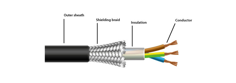
Image disclaimer: For identification and illustration only. It may show a product by another manufacturer and may not depict the exact item described; it is not a statement of any product’s quality, approval or performance. Third-party image and trademark rights belong to their owners. See full notice.
What Is It?
A Shielded Cable (also known as a screened cable or EMI‑shielded cable) is a cable that incorporates a metallic layer—either a braided copper mesh, a spirally wound copper tape, or a combination—to protect the internal conductors from external electromagnetic interference (EMI) and to prevent the cable itself from radiating interference. In airfield ground lighting (AGL) systems, shielded cables are essential for maintaining signal integrity in control, monitoring, and communication circuits that are susceptible to interference from high‑power transmitters, radar systems, and other electrical equipment.
Key characteristics of shielded cables include:
- Metallic Screen: A conductive layer that surrounds the insulated conductors, providing a barrier against electromagnetic fields.
- EMI Suppression: The screen reduces both radiated emissions (from the cable) and conducted susceptibility (interference picked up by the cable).
- Earthing/Bonding: The screen must be properly terminated and earthed to be effective, providing a low‑impedance path for interference currents.
- Variety of Types: Available as single‑pair, multi‑pair, or multi‑core cables, with various screen constructions (braid, foil, or combined).
Shielded cables are used in AGL systems for:
- Control circuits: Between CCRs and field equipment, such as brightness control and switching signals.
- Monitoring and feedback: From ALCMS sensors and status indicators.
- Communication links: For data transmission between AGL equipment and the ALCMS, often with RS‑485, Ethernet, or other protocols.
- Sensor cables: For weather sensors, RVR sensors, and other sensitive instrumentation.
Proper selection, installation, and termination of shielded cables are critical to achieving the required EMC performance and ensuring the reliable operation of AGL systems.
Purpose & Function
Shielded cable exists to keep low-level control, monitoring, and communication signals trustworthy in an environment saturated with sources of electrical noise, from high-power CCR switching to radar and transmitter equipment nearby. Without the metallic screen, induced interference on these circuits could corrupt sensor readings, garble ALCMS data links, or trigger false control signals, all of which would undermine confidence in the monitoring system the AGL infrastructure depends on. The screen only delivers this protection when it is correctly terminated to earth at every point along the run, which is why the cable's shielding performance is inseparable from the quality of its screen termination rather than a property of the cable alone.
Where Is It Used?
Shielded cables are used throughout the airfield wherever electromagnetic compatibility (EMC) is a concern, including:
- AGL Control and Monitoring Systems: Connecting CCRs, ALCMS workstations, and field controllers to transmit control signals and receive status updates.
- Data Communication Networks: Ethernet cables (e.g., CAT‑5/6 with FTP or STP) for ALCMS network infrastructure.
- Sensor Wiring: Connecting wind sensors, visibility sensors, RVR sensors, and pavement temperature sensors to data acquisition units.
- ILS and Navigation Aid Cables: Interconnecting ILS localizer and glide slope equipment, where signal integrity is paramount.
- Fibre Optic Cable Metallic Members: Shielded cables are sometimes used for the metallic strength members of fibre optic cables to provide lightning protection and EMI shielding.
- Retrofit and Upgrades: Replacing unshielded cables in existing installations to improve EMC performance, especially when new radar or communication equipment is added.
The cable type is selected based on the application—single pair for simple signals, multi‑pair for multiple channels, and overall screen (with or without individual screens) depending on the required level of shielding. The screen material (copper, tinned copper, or aluminium) and coverage (often ≥ 80% for braid, 100% for foil) are chosen to meet the specific EMC requirements.
Installation & Location
The cable is routed separately from primary and secondary power cables wherever practicable, typically in its own duct or a dedicated section of a shared trench, to limit the electromagnetic coupling between high-current power circuits and the lower-level control, monitoring, or communication signals the shielded cable carries. Where it must cross a power cable route, the crossing is made at as close to a right angle as possible to minimise the length of parallel run between the two. At each termination — whether at a CCR, ALCMS controller, sensor, or junction box — the cable's screen is bonded to earth using a screen connector, since the shielding is only effective when properly earthed at its termination points. Runs are kept as short and direct as the site layout allows, with excess coiled cable avoided, as a coiled or looped run can itself act as an inductive element that undermines the very interference suppression the shielding is intended to provide.
How Does It Work?
A shielded cable works by providing a conductive barrier between the internal signal conductors and the external environment. The screen intercepts electromagnetic fields and diverts interference currents to earth, preventing them from reaching the signal conductors. The functional principles are based on electromagnetic theory:
- Reflection and Absorption: The metallic screen reflects a portion of the incident electromagnetic wave and absorbs the remainder, reducing the field strength inside the cable.
- Low‑Impedance Path: When the screen is connected to earth at one or both ends, it provides a low‑impedance path for induced currents, preventing them from propagating along the screen and coupling into the conductors.
- Transfer Impedance: The effectiveness of the screen is characterised by its transfer impedance—the lower the transfer impedance, the better the shielding. Braided screens have higher transfer impedance at high frequencies than solid or foil screens.
- Termination: The screen must be terminated to earth using a screen connector or gland to be effective. A poorly terminated screen can act as an antenna, worsening EMI.
In AGL systems, shielded cables are used for both analog and digital signals. For analog signals (e.g., 4‑20 mA current loops, 0‑10 V voltage signals), shielding prevents noise pickup that could cause measurement errors. For digital signals (e.g., RS‑485, Ethernet), shielding reduces bit errors and ensures reliable communication in noisy environments.
System Architecture & Control Logic
Shielding only works if the screen is terminated to earth — an unterminated screen can act as an antenna and worsen EMI.
Physical Construction
Shielded cable adds one construction layer on top of an otherwise conventional multi‑core design. Each internal conductor — annealed copper, tinned or bare, single‑pair, multi‑pair, or multi‑core depending on the circuit — is individually insulated and, where multiple pairs are present, laid up (twisted together) to cancel out mutual interference before the whole core bundle is wrapped. The screen itself is applied over this core as a braided copper mesh, a helically wound (spiral) copper tape, an aluminium‑polyester foil, or a combination of foil‑plus‑drain‑wire, chosen according to the frequency range and level of EMI rejection the circuit needs, with braid giving the most robust, flexible coverage and foil giving the most complete high‑frequency shielding at lower cost. An overall outer jacket of PVC, PE, or a similarly tough polymer is extruded over the screen to protect it mechanically and environmentally. The screen is only effective once terminated: at each cable end it is drawn out, twisted into a pigtail or connected via a screen connector, and bonded to earth, so the finished installation's shielding performance depends as much on that termination as on the cable's own construction.
Technical Parameters
| Parameter | Typical Value |
|---|---|
| Conductor Material | Annealed copper (EC grade), tinned or bare |
| Conductor Size (Cross‑section) | 0.5mm² to 2.5mm² (AWG 20 to 14) — varies by application |
| Number of Conductors | 1‑pair, 2‑pair, 4‑pair, or multi‑core (up to 50 cores) |
| Insulation Material | PE, XLPE, EPR, or PVC (colour‑coded for identification) |
| Screen Type | Braid (tinned copper), foil (aluminium/polyester), or combination |
| Screen Coverage | ≥ 80% (braid), 100% (foil) |
| Overall Sheath Material | PVC, LSZH, or TPU (oil‑resistant) |
| Rated Voltage | 0.6/1kV (power); 300/500V (control) |
| Operating Temperature | -40°C to +90°C (XLPE); -40°C to +70°C (PVC) |
| Transfer Impedance (at 10 MHz) | ≤ 10 mΩ/m (braid); ≤ 1 mΩ/m (foil) — typical |
| Standards | IEC 60332, IEC 61034, IEEE 1100, FAA AC 150/5345‑7 |
Electrical Requirements
| Requirement | Typical Value |
|---|---|
| Circuit Type | Passive conductor — carries current per its rated voltage and conductor size; provides no protection or regulation itself |
| Rated Voltage | 0.6/1kV (power cores) or 300/500V (control cores), per construction |
| Conductor Rating | Sized per cross-section (0.5–2.5mm² / AWG 20–14) for the intended circuit's current |
| Screening/Earthing | Braid or foil screen bonded to earth at one end (or both, per design) to drain induced/interference currents |
| Insulation Rating | Governed by insulation material (PE/XLPE/EPR/PVC) and the rated voltage class |
| Fault Protection | None internal — protection is provided by upstream devices (CCR, circuit breakers, fuses) |
| Standards | IEC 60332, IEC 61034, IEEE 1100, FAA AC 150/5345-7 |
Applicable Standards
IEC 60332
Tests on electric and optical fibre cables under fire conditions (flame retardancy)
IEC 61034
Measurement of smoke density of cables burning under defined conditions
IEEE 1100
Recommended practice for powering and grounding electronic equipment (EMC)
FAA AC 150/5345‑7
Specification for L-824 underground electrical cable for airport lighting circuits
Installation Requirements
Route Segregation from Power Cabling
CivilRoute the cable separately from primary and secondary power cables wherever practicable, in its own duct or a dedicated section of a shared trench.
Power Cable Crossing Angle
CivilWhere the route must cross a power cable, make the crossing as close to a right angle as possible to minimise the length of parallel run between the two.
Screen/Shield Termination
ElectricalTerminate the cable's screen at each end — CCR, ALCMS controller, sensor, or junction box — per the design's earthing scheme, avoiding an unintended second earth point that would create a ground loop.
Bend Radius & Pulling Tension
MechanicalKeep the cable within its minimum bend radius and rated pulling tension during installation to avoid damaging the shield or conductors.
Pre-Energisation Sign-off
DocumentationRecord route, crossing points, and screen termination as-built before the cable is connected and energised.
Testing & Commissioning
Screen/Shield Continuity Test
Pre-EnergisationVerify continuity of the cable's overall screen end to end, ruling out a broken shield introduced during installation.
Insulation Resistance (Megger) Test
Pre-EnergisationMegger-test conductor-to-conductor and conductor-to-screen before backfill, confirming insulation resistance clears the acceptable minimum.
EMC / Shield Effectiveness Check
Final AcceptanceConfirm the screen is bonded and terminated correctly at both ends per the design to maintain rated shielding effectiveness.
Route & Segregation Verification
Pre-EnergisationConfirm burial route and separation from power cables or other EMI sources match the design drawing before the trench is closed.
Documentation & As-Built Sign-off
Final AcceptanceRecord continuity, insulation, and shielding check results alongside as-built routing in the commissioning dossier for handover.
Inspection & Maintenance
Screen Continuity & Resistance Test
AnnualTest screen continuity end-to-end and measure resistance, since damage from cable pulling or crushing can silently reduce shielding effectiveness.
Termination & Earth Bond Check
AnnualConfirm the screen is terminated with 360° contact, kept short (ideally under 50mm), and earthed per the equipment manufacturer's single- or dual-end recommendation.
Ground Loop Check
AnnualVerify the screen is not inadvertently earthed at both ends of a long run in a way that creates a ground loop and induces noise.
Insulation Resistance Test
AnnualMegger-test conductor insulation to confirm resistance stays above the minimum, catching moisture ingress through a damaged sheath before it causes a fault.
Sheath Damage Inspection
Semi-annualInspect the overall sheath for cuts, abrasion, or crushing along accessible runs, which are common entry points for moisture and screen corrosion.
EMC Performance Verification
AnnualConfirm transfer impedance and shielding effectiveness remain adequate for the interference environment, especially where cable type or screen coverage was substituted during repairs.
Gland & Seal Inspection
AnnualCheck sealing glands and terminations at enclosure entries for degradation, since a compromised seal is a primary path for moisture ingress.
Bend Radius & Routing Check
Semi-annualConfirm routed cable has not been pulled around sharp bends or over cable rollers incorrectly, which can crush the screen and reduce shielding effectiveness.
Common Field Issues
Improper Screen Termination
One of the most common issues is a poorly terminated screen—either not connected to earth or connected with a long pigtail that increases impedance. Use a screen connector or gland that provides 360° contact, and keep the screen termination short (ideally < 50mm) and direct to an earth bus.
Ground Loops
Connecting the screen at both ends in a long run can create a ground loop, inducing noise. Typically, the screen should be earthed at one end (usually the source or panel end). For high‑frequency applications, earthing at both ends with low‑impedance connections may be required. Follow the equipment manufacturer's recommendations.
Screen Damage During Installation
The screen can be damaged (cut, frayed, or crushed) during cable pulling, reducing shielding effectiveness. Handle cables carefully, use cable rollers, and avoid sharp bends. After installation, test the screen continuity and resistance.
Moisture Ingress
Moisture can enter the cable through damaged sheath or terminations, causing corrosion of the screen and conductors. Use moisture‑blocking materials, proper sealing glands, and inspect cables for sheath damage.
EMC Failure Due to Incorrect Cable Type
Using a cable with insufficient shielding (e.g., a braid with low coverage) for a high‑interference environment can lead to EMC problems. Ensure the cable's screen type and coverage meet the required EMC level for the application.
Screen Not Connected to Earth at All
In some installations, the screen is left floating, which renders the shielding ineffective. Always connect the screen to a proper earth point. Use a dedicated earth bar for screen terminations.
Crosstalk Between Pairs
In multi‑pair cables, crosstalk between pairs can occur if the pairs are not individually shielded or if the overall shield is insufficient. Use individually shielded pairs (e.g., twisted pairs with foil screens) for sensitive signals.
Troubleshooting Guide
EMI/Noise on Signal Despite Shielded Cable
Noise Consistent with a Ground Loop
Reduced Shielding Effectiveness After Installation
Insulation or Screen Resistance Failure
EMC Failure at Commissioning or Retest
Crosstalk Between Pairs in a Multi-Pair Cable
Failure Modes & Root Causes
Poor Screen Termination
Ground Loop from Multi-Point Earthing
Screen Mechanical Damage During Installation
Moisture Ingress / Insulation Breakdown
Insufficient Screen Coverage for the Application
Safety & Operational Notes
Isolate Before Termination Work
Electrical SafetyDe-energise and lock out the associated circuit before terminating, splicing, or reworking shielded cable, since control and monitoring cables can share routes or ducts with higher-energy circuits.
Single-Point Earth the Screen
OperationalTerminate the cable screen at a single point per the system design, typically at the control end, to avoid creating a ground loop; earthing the screen at both ends is a common and hard-to-diagnose source of interference.
Handle the Screen Carefully During Installation
OperationalAvoid nicking, crushing, or excessively bending the cable during pulling and termination, since damage to the screen or jacket compromises both shielding effectiveness and weatherproofing.
Verify Screen Continuity Before Closing Out
ComplianceTest screen continuity and insulation resistance after termination and before commissioning, so a damaged or poorly terminated screen is caught before it manifests as intermittent interference.
Seal Terminations Against Moisture
OperationalProperly seal glands, boots, and enclosure entries after termination to keep moisture out of the cable end and connector, preventing insulation breakdown over time.
Confirm Signal Integrity After Work
ComplianceAfter any cable or termination work, confirm the associated control or monitoring signal is clean and stable before closing out the task.
Engineering & Expert Notes
A Shield Grounded at Both Ends Can Create a Ground Loop
DesignBonding a cable shield to earth at both ends, rather than following the specified single-point grounding scheme, can introduce a ground loop that shows up as noise on the signal rather than an obvious fault. Verify the shield termination scheme matches the design intent whenever a cable is re-terminated.
Intermittent Noise Often Traces to a Damaged Shield, Not the Conductors
DiagnosticsA signal that picks up noise only when nearby equipment cycles on and off frequently points to a compromised or poorly terminated shield rather than a fault in the core conductors themselves. Check shield continuity and termination before assuming the conductors are at fault.
Tight Bend Radii Damage Shield Coverage Invisibly
InstallationPulling a shielded cable around a bend tighter than its rated minimum radius can gap or thin the shield's braid coverage without any visible damage to the outer jacket, degrading its shielding effectiveness. Respect the manufacturer's minimum bend radius during installation and re-routing alike.
Moisture at an Unsealed Termination Corrodes the Shield First
DurabilityA shield braid or foil is often more susceptible to corrosion from moisture ingress than the insulated core conductors, so a termination that looks fine electrically on the core can still have a degraded shield. Inspect shield condition specifically at every termination check, not just core conductor continuity.
Don't Run Shielded and Unshielded Circuits in the Same Duct Without Checking Separation
DesignRouting a shielded signal cable in close proximity to a high-current power cable in the same duct can still induce noise if separation distance falls short of the design guidance, even with the shield correctly terminated. Verify duct separation against the applicable standard, not just shield presence.
Record Shield Continuity Separately From Core Continuity
ProcessLogging shield continuity as its own line item, rather than folding it into a general cable pass/fail result, makes it possible to spot a shield-specific degradation trend on a particular run that a combined result would mask.
Frequently Asked Questions
Short answers about the Shielded Cable: what it is, how it works, typical specifications, standards, maintenance and common faults.
Q1What is a Shielded Cable?
A Shielded Cable (also known as a screened cable or EMI‑shielded cable) is a cable that incorporates a metallic layer—either a braided copper mesh, a spirally wound copper tape, or a combination—to protect the internal conductors from external electromagnetic interference (EMI) and to prevent the cable itself from radiating interference. In airfield ground lighting (AGL) systems, shielded cables are essential for maintaining signal integrity in control, monitoring, and communication circuits that are susceptible to interference from high‑power transmitters, radar systems, and other electrical equipment.
Q2What is the purpose of a Shielded Cable?
Shielded cable exists to keep low-level control, monitoring, and communication signals trustworthy in an environment saturated with sources of electrical noise, from high-power CCR switching to radar and transmitter equipment nearby. Without the metallic screen, induced interference on these circuits could corrupt sensor readings, garble ALCMS data links, or trigger false control signals, all of which would undermine confidence in the monitoring system the AGL infrastructure depends on.
Q3Where is a Shielded Cable used and installed?
Shielded cables are used throughout the airfield wherever electromagnetic compatibility (EMC) is a concern, including: AGL Control and Monitoring Systems: Connecting CCRs, ALCMS workstations, and field controllers to transmit control signals and receive status updates. Data Communication Networks: Ethernet cables (e.g., CAT‑5/6 with FTP or STP) for ALCMS network infrastructure. Sensor Wiring: Connecting wind sensors, visibility sensors, RVR sensors, and pavement temperature sensors to data acquisition units. ILS and Navigation Aid Cables: Interconnecting ILS localizer and glide slope equipment, where signal integrity is paramount.
Q4How does a Shielded Cable work?
A shielded cable works by providing a conductive barrier between the internal signal conductors and the external environment. The screen intercepts electromagnetic fields and diverts interference currents to earth, preventing them from reaching the signal conductors. The functional principles are based on electromagnetic theory: Reflection and Absorption: The metallic screen reflects a portion of the incident electromagnetic wave and absorbs the remainder, reducing the field strength inside the cable.
Q5What are the typical technical parameters of a Shielded Cable?
Typical values are — Conductor Material: Annealed copper (EC grade), tinned or bare; Conductor Size (Cross‑section): 0.5mm² to 2.5mm² (AWG 20 to 14) — varies by application; Number of Conductors: 1‑pair, 2‑pair, 4‑pair, or multi‑core (up to 50 cores); Insulation Material: PE, XLPE, EPR, or PVC (colour‑coded for identification); Screen Type: Braid (tinned copper), foil (aluminium/polyester), or combination; Screen Coverage: ≥ 80% (braid), 100% (foil); Overall Sheath Material: PVC, LSZH, or TPU (oil‑resistant); Rated Voltage: 0.6/1kV (power); 300/500V (control); Operating Temperature: -40°C to +90°C (XLPE); -40°C to +70°C (PVC).
Q6What are the electrical requirements for a Shielded Cable?
Typical requirements are — Circuit Type: Passive conductor — carries current per its rated voltage and conductor size; provides no protection or regulation itself; Rated Voltage: 0.6/1kV (power cores) or 300/500V (control cores), per construction; Conductor Rating: Sized per cross-section (0.5–2.5mm² / AWG 20–14) for the intended circuit's current; Screening/Earthing: Braid or foil screen bonded to earth at one end (or both, per design) to drain induced/interference currents; Insulation Rating: Governed by insulation material (PE/XLPE/EPR/PVC) and the rated voltage class.
Q7Which standards apply to a Shielded Cable?
The main references are IEC 60332 — Tests on electric and optical fibre cables under fire conditions (flame retardancy); IEC 61034 — Measurement of smoke density of cables burning under defined conditions; IEEE 1100 — Recommended practice for powering and grounding electronic equipment (EMC); FAA AC 150/5345‑7 — Specification for L-824 underground electrical cable for airport lighting circuits. Always verify the current edition and your aerodrome's approved requirements.
Q8How often should a Shielded Cable be inspected and maintained?
Typical maintenance tasks and intervals are: Screen Continuity & Resistance Test (annual); Termination & Earth Bond Check (annual); Ground Loop Check (annual); Insulation Resistance Test (annual); Sheath Damage Inspection (semi-annual); EMC Performance Verification (annual); Gland & Seal Inspection (annual); Bend Radius & Routing Check (semi-annual). Your airport's approved maintenance programme takes precedence.
Q9How do I troubleshoot common Shielded Cable faults?
Common symptoms covered are: EMI/Noise on Signal Despite Shielded Cable; Noise Consistent with a Ground Loop; Reduced Shielding Effectiveness After Installation; Insulation or Screen Resistance Failure; EMC Failure at Commissioning or Retest; Crosstalk Between Pairs in a Multi-Pair Cable. For example, for "EMI/Noise on Signal Despite Shielded Cable": Likely Cause: The screen is poorly terminated — not connected to earth, or connected through a long pigtail that increases high-frequency impedance. Diagnostic Steps: Inspect the screen termination for pigtail length and earth bond; test screen continuity end to end; check the noise symptom against known interference sources nearby. Corrective Action: Re-terminate with a screen connector or gland providing 360° contact, keeping the termination short and direct to an earth bus.
Related Components
Go Beyond the Component. Understand the Complete AGL System.
You have explored the component. Now understand how it works within the complete Airfield Ground Lighting system.
Learn AGL from fundamentals to design, installation, testing, photometry, commissioning, maintenance and troubleshooting through structured technical training at Precision AGL Academy.
Build practical knowledge. Understand the circuit. Read the standards. Troubleshoot with confidence.
Your next step in AGL starts here.
Need expert guidance on shielded cable selection and installation for your AGL project?
Precision AGL Academy provides advice on cable type selection, screen termination techniques, and EMC best practices for reliable AGL systems.
Follow the Academy
Important Notice, Disclaimer & Limitation of Liability
Please read before relying on any content on this page.
- Purpose and intended users. This page on Shielded Cable is an independent educational and informational reference for competent, suitably trained and authorised airfield ground lighting (AGL) and aerodrome electrical personnel. It is not professional engineering, legal or regulatory advice, and using it does not create any professional or client relationship.
- Safety. Work on series circuits, constant current regulators (CCRs), isolating transformers, cables, connectors and lighting equipment can be fatal. Always apply the aerodrome’s permit-to-work and isolation/LOTO procedures, prove dead, use correctly rated instruments and PPE, and follow the manufacturer’s instructions. Nothing here authorises work on live equipment or the bypassing of any safety device or interlock.
- Aviation operations. Nothing here authorises installation, modification, energisation, adjustment, return to service, a change of operating category (CAT I/II/III), a NOTAM or any aerodrome certification or approval decision. These rest with the aerodrome operator, the air navigation service provider and the competent regulator.
- Specifications, ratings and typical values. Descriptions, parameters, ratings, dimensions, photometric values, wattages, service lives, maintenance tasks and intervals, failure modes, certifications (for example CE, FCC, UL or IEC marks) and part or type designations are general, typical and indicative. They may not match any particular product, make, model or version, and they are not a datasheet, design, specification, selection, sizing, procurement or acceptance criterion. The manufacturer’s current documents, the approved design and the project specification prevail.
- Standards and regulations. References to ICAO, FAA, IEC, IEEE, ISO, BIS, DGCA and other standards are paraphrased summaries for orientation only. They may be incomplete or out of date, and standards are revised from time to time. Consult the current official editions. Following this content does not guarantee compliance with any law, standard or regulatory approval, and the regulator’s requirements always prevail.
- No warranty. Content is provided “as is” and “as available”, without warranty of any kind, express or implied, including accuracy, completeness, currency or fitness for a particular purpose. Real installations differ in design, equipment make and model, age and condition.
- Limitation of liability. To the fullest extent permitted by applicable law, Precision AGL Academy, Precision AGL Solutions and their owners, authors and contributors are not liable for any injury, death, loss, damage, downtime, penalty or regulatory consequence, whether direct or indirect, arising from the use of, reliance on, or inability to use this content. Nothing in this notice excludes or limits any liability that cannot lawfully be excluded or limited.
- Independence, brands and no endorsement. This is an independent publication. It is not affiliated with, sponsored by or endorsed by ICAO, the FAA, the IEC, DGCA, AAI, any airport, regulator, supplier or equipment manufacturer. Third-party names, product designations, standard designations and trademarks (including Megger®, Siemens, Eaton, Crouse-Hinds, ADB SAFEGATE, Fluke, ABB and Honeywell) belong to their respective owners and are used only for identification and description. Mention of a brand, product or supplier is not a recommendation, and we do not sell, supply or quote for any component described.
- Images and third-party content. Images and illustrations are shown to help identify the type of component. They may show products of various manufacturers, may not depict the exact item described, and are not a statement about any product’s quality, approval or performance. Copyright and trademarks in third-party images, logos and photographs belong to their respective owners and are not claimed as ours. If you are a rights holder and want an image removed, replaced or credited, email precisionaglsolutions@gmail.com with the page address and we will act promptly.
- Training and services. Mentions of training, courses, consultation, advice, selection, installation, calibration or other support, including the “Learn…Certify” pathway, describe learning stages and are not an offer, quotation, tender or promise of any result. Contacting us or our replying creates no engagement or duty of care; an engagement exists only under a written agreement. We are not a regulator or certification body, and completing any course or reading this content is not a certification, accreditation or authorisation to work on any aerodrome.
- Copyright, privacy and corrections. © 2026 Precision AGL Academy. All rights reserved. Text, structure, compilations and diagrams may be viewed for personal reference and internal training only; any other copying, republication or commercial use needs our written permission. If you email, telephone or message us, we use your details only to respond and handle your matter, in line with applicable Indian law including the Digital Personal Data Protection Act, 2023; please do not send confidential or security-sensitive information. To display this page your browser requests fonts, icons and images from third-party servers, which receive your IP address and browser details under their own policies. Content is reviewed periodically with no obligation to update. To report an error, safety concern or rights issue, write to precisionaglsolutions@gmail.com.