Top Cover
The uppermost protective component of an AGL fixture, sealing the housing and securing internal components. Designed to withstand impact, provide environmental sealing, and, in many cases, incorporate the optical window or lens for light output.
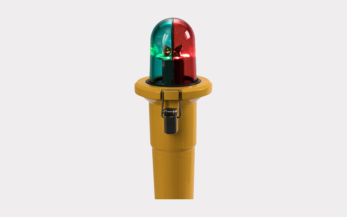
Image disclaimer: For identification and illustration only. It may show a product by another manufacturer and may not depict the exact item described; it is not a statement of any product’s quality, approval or performance. Third-party image and trademark rights belong to their owners. See full notice.
What Is It?
The Top Cover is the uppermost component of an AGL fixture, serving as the primary protective barrier between the internal optical and electronic components and the harsh outdoor environment. It is typically made from durable materials such as die-cast aluminium, stainless steel, or high-strength engineering plastics. The top cover may incorporate the optical window (lens), a prism assembly, or a clear cover plate that allows light to exit while protecting the light source and optics from moisture, dust, and mechanical impact. It is secured to the fixture housing using screws, bolts, or a threaded ring, and is sealed with a gasket or O-ring to maintain the fixture's IP67/IP68 rating. In inset fixtures, the top cover is designed to be flush with the pavement surface and must withstand heavy aircraft loads.
Purpose & Function
The top cover's purpose is to keep an AGL fixture's light output reliable and its interior safe from the environment, without compromising the beam that pilots depend on for guidance. It is the fixture's first line of defence against moisture, dust, bird strikes, and debris, so a fixture that has been sealed and protected for years will still perform to its original photometric specification rather than degrading or short-circuiting internally. Where the cover doubles as the optical window, this protective role has to be balanced against optical transparency and precise shape, since any distortion or fogging would blur or misdirect the beam. In inset fixtures the cover takes on a third, safety-critical role: bearing the repeated weight of aircraft wheels without deforming, so the fixture remains flush and does not itself become a hazard to tyres or landing gear.
Where Is It Used?
Top covers are used in virtually every AGL fixture type, with design variations for specific applications:
- Runway Edge Lights (Elevated): Top cover with lens/prism for beam projection, secured by a threaded ring or screws.
- Runway Edge Lights (Inset): Heavy-duty steel or cast-iron cover with an optical window, designed to withstand 100,000 kg wheel loads.
- Runway Centreline Lights: Flush-mounted cover with a bi-directional optical assembly.
- Threshold & End Lights: Cover with green/red filter and uni-directional optics.
- Taxiway Lights: Cover with blue or green lens, often with a low profile.
- Approach Lighting: Covers for barrette housings, often with clear lenses.
- PAPI & VASI: Precision covers with colour filters and optical alignment features.
- Obstruction Lights: Covers with hemispherical or flat lenses for 360° visibility.
Installation & Location
The top cover seats onto the bottom housing over a gasket, secured by a threaded retaining ring, screws, or a bayonet-style twist-lock depending on fixture type, with bolts or the ring torqued evenly around the perimeter so the gasket compresses uniformly and the joint seals fully. On inset fixtures, the cover is set so its upper face finishes flush with the surrounding pavement once fitted, ready to take direct wheel loading, while elevated fixtures instead need the cover correctly orientated to any beam-shaping lens or prism it carries. Where the cover integrates the optical assembly, its rotational alignment is set to an index mark so the beam or colour filter faces the correct direction before the final fasteners are tightened, and it's refitted with a new gasket each time the fixture is opened for lamp, LED, or internal servicing.
How Does It Work?
The top cover performs several essential functions in an AGL fixture:
- Environmental Protection: Seals the housing against moisture, dust, and contaminants using a gasket or O-ring, maintaining the required IP rating.
- Mechanical Protection: Protects the internal optical components (prism, lens, reflector) and light source (LED or lamp) from impact damage, bird strikes, and debris.
- Optical Output: In many fixtures, the top cover incorporates the optical window or lens that allows light to exit with the required beam pattern.
- Load Bearing (Inset Fixtures): For flush-mounted fixtures, the top cover is designed to withstand repeated aircraft tyre loads (up to 100,000 kg) without deformation or failure.
- Thermal Management: The cover may act as a heat sink or provide ventilation paths to dissipate heat from the light source.
- Security & Tamper Resistance: Covers are often secured with tamper-proof fasteners to prevent unauthorised access.
The top cover is typically the first component to be removed during maintenance, allowing access to the lamp, LED module, or optics for inspection and replacement.
Multi-Function Overview & Control Logic
One physical part performs all six roles at once — it's also usually the first thing removed for maintenance access.
Physical Construction
The top cover is die-cast, machined, or moulded from aluminium alloy, stainless steel, or a high-strength engineering plastic, formed as a single shell that carries the lens or prism window in a machined recess or moulded-in aperture. Where the cover incorporates the optical window directly, that window is gasket- or O-ring-sealed into its recess before the cover itself is fitted to the housing, so the cover ships as one pre-sealed sub-assembly rather than requiring the glazing to be fitted in the field. The cover-to-housing joint runs the full perimeter and is compressed against a gasket or O-ring by screws, bolts, or a threaded ring, chosen so the fixture's IP67/IP68 rating is maintained through repeated opening for lamp or driver access. On inset fixtures the cover is additionally built to a load-rated thickness and edge-support profile so it survives direct aircraft wheel loading while sitting flush with the pavement surface.
Technical Parameters
| Parameter | Typical Value |
|---|---|
| Material | Die-cast aluminium (A380), stainless steel (316L), or engineering plastic (PC, PA) |
| Surface Finish | Powder-coated (RAL colours), anodized, or polished |
| Optical Window | Tempered glass, polycarbonate, or acrylic lens (clear or coloured) |
| Load Capacity (Inset) | 100,000 kg (220,000 lbs) wheel load |
| Impact Resistance | IK10 (20J) for elevated fixtures |
| Sealing | Silicone or EPDM gasket/O-ring, IP67/IP68 rated |
| Fastening | Screws, bolts, or threaded ring (stainless steel) |
| Temperature Range | -40°C to +80°C (continuous) |
| UV Resistance | UV-stabilised coatings and materials |
| Corrosion Resistance | Salt spray tested (500+ hours, ASTM B117) |
Applicable Standards
FAA AC 150/5345-46
Specification for Runway, Taxiway, Heliport, and Vertiport Light Fixtures — includes cover and housing requirements
IEC 60529
Degrees of protection provided by enclosures (IP code)
IEC/TS 61827
Characteristics of inset and elevated aerodrome luminaires — environmental and mechanical performance
ASTM B117
Salt spray (fog) testing for corrosion resistance
Installation Requirements
New Gasket Fitting
FitFit a new gasket each time the cover is refitted after opening the fixture for lamp, LED, or internal servicing, rather than reusing the existing one.
Even Perimeter Torque
FitTorque bolts or the retaining ring evenly around the full perimeter, in the manufacturer's specified sequence, so the gasket compresses uniformly and the joint seals fully.
Optical Index Alignment
FitWhere the cover integrates the optical assembly, set its rotational alignment to the index mark so the beam or colour filter faces the correct direction before final fasteners are tightened.
Flush Seating (Inset Fixtures)
FitOn inset fixtures, confirm the upper face finishes flush with the surrounding pavement once fitted, so it takes direct wheel loading as designed.
Pre-Fit Window Check
Pre-FitWhere the cover ships as a pre-sealed sub-assembly with the lens or prism window already fitted, confirm that window's seal is intact before mounting the cover to the housing.
Pre-Energisation Sign-off
DocumentationRecord gasket replacement, torque values, and orientation before the fixture is returned to service, since the seal is not inspectable once the cover is closed.
Testing & Commissioning
Fastener Torque Check
InstallationTorque the top cover's fasteners or threaded retaining ring to the specified value in the correct sequence for even seal compression.
Gasket/Seal Compression Check
InstallationConfirm the gasket or O-ring compresses evenly around the full perimeter once the cover is secured.
Ingress Protection Verification
Final AcceptancePressure or water-immersion test the assembled fixture to confirm the top cover seal achieves the required IP67/IP68 rating.
Load Verification
Final AcceptanceFor inset fixtures, confirm the cover withstands the rated aircraft wheel load without deflection or seal failure.
Documentation & As-Built Sign-off
Final AcceptanceRecord torque values and IP/load test results in the commissioning dossier for handover.
Inspection & Maintenance
Corrosion & Paint Inspection
AnnualCheck the cover for corrosion and paint degradation such as chalking or fading from UV exposure.
Gasket & Seal Check
AnnualInspect the cover's gasket or O-ring for compression set or damage that could let moisture into the fixture.
Fastener Condition Check
AnnualCheck fasteners for seizing or stripped threads, and apply anti-seize where appropriate during reassembly.
Cleaning
QuarterlyClean the cover and any integrated lens area of rubber deposits and debris to maintain appearance and light output.
Common Field Issues
Corrosion of Metal Covers
In coastal or high-humidity environments, die-cast aluminium covers can corrode, especially if the powder coating is damaged. This can lead to seizing of fasteners and loss of structural integrity. Use stainless steel covers or marine-grade coatings in such environments.
Gasket/O-Ring Failure
The sealing gasket or O-ring can degrade over time, leading to moisture ingress and internal corrosion. Regular inspection and replacement of seals during maintenance is essential.
Lens Cracking or Scratching
The optical window (lens) in the top cover can crack due to thermal shock or impact, or become scratched from cleaning or debris. Cracks or deep scratches reduce light output and compromise the seal. Replace the top cover or lens assembly if damaged.
Stripped or Seized Fasteners
Over-tightening or corrosion can strip or seize the screws or bolts securing the top cover. This makes maintenance difficult and can lead to damage during removal. Use anti-seize compounds and torque wrenches to prevent this.
Paint Degradation (UV Fading, Chalking)
Powder-coated covers can fade or chalk due to UV exposure. While this is primarily cosmetic, severe degradation can expose the metal substrate to corrosion. Re-painting or replacing the cover may be required.
Troubleshooting Guide
Moisture Found Inside the Fixture Under the Top Cover
Cover Won't Come Off / Fasteners Stripped or Seized
Visible Corrosion on the Cover
Reduced Light Output Through the Cover's Optical Window
Failure Modes & Root Causes
Seal Degradation
Fastener Seizure
Coating Failure / Corrosion
Optical Window Damage
Safety & Operational Notes
Verify Isolation Before Removal
Electrical SafetyThe top cover is the only barrier between exposed hands and the live optical/electronic assembly beneath it; de-energise and lock out the fixture's CCR and verify zero energy before removing the cover, even for a routine lens clean or inspection.
Inset Cover Load Rating
MechanicalOn inset fixtures the top cover sits flush with the pavement and carries direct aircraft wheel loads; use only the manufacturer-rated cover for the fixture and confirm it seats flush and secure before reopening the surface to traffic.
Seal Integrity on Reinstatement
MechanicalInspect the gasket or O-ring for damage, dirt, or compression set every time the cover is removed, and replace it if in doubt; a compromised seal lets in moisture and dust and defeats the fixture's IP67/IP68 rating.
Lens/Window Handling
Personnel SafetyHandle the optical window or prism section by its edges and avoid abrasive cleaning agents or dry wiping under grit, since scratches or thermal shock can crack the cover and reduce light output.
Airside Work Coordination
OperationalAny work that removes or leaves a fixture without its top cover requires ATC/airside coordination and a NOTAM where the fixture will be dark, out of tolerance, or an FOD/load risk, with vehicle and personnel movement kept clear per the aerodrome's safety management procedures.
FOD Control at the Fixture
OperationalKeep the retaining screws, threaded ring, or bolts accounted for at all times while the cover is off, and never leave a fixture open or loosely capped, to prevent foreign object debris on the movement area.
Correct Torque on Reinstatement
MechanicalTighten retaining fasteners or the threaded ring to the manufacturer's specified torque; under-tightening compromises the seal and traffic load rating, while over-tightening can crack the cover or strip the housing threads.
Restore to Compliant State
ComplianceDo not leave a fixture with a cracked, hazed, or misaligned cover after maintenance; verify the seal, seating, and photometric output through the window before closing out the work and cancelling the associated NOTAM.
Engineering & Expert Notes
Load Rating Applies to the Whole Assembly, Not Just the Cover Material
MechanicalAn inset top cover's wheel-load rating depends on correct engagement with its housing and retaining hardware, not the cover material alone; a rated cover installed with under-torqued fasteners or a worn retaining thread can fail under load well below its stated rating.
IP Rating Is Lost the Moment the Gasket Compresses Unevenly
DurabilityA top cover gasket compressed unevenly from a warped cover or debris trapped under one edge can leave the fixture's IP67/IP68 rating compromised even though the cover appears fully seated and secured; check for even gasket compression around the full perimeter, not just that the cover is tight.
Internal Corrosion Can Precede Any External Sign on the Cover
TroubleshootingMoisture entry through a marginal cover seal corrodes internal components before it produces any visible sign on the cover itself; where a fixture shows unexplained intermittent faults, inspect the cover seal even if the cover looks undamaged.
Torque Sequence Matters as Much as Torque Value on Multi-Bolt Covers
WorkmanshipTightening multi-bolt or multi-screw covers in a random order can leave the gasket unevenly compressed even when every fastener reaches its specified torque; tighten in a cross or star pattern to seat the seal evenly.
A Cover That 'Mostly' Seats Isn't Seated
MechanicalA cover that goes on with noticeable resistance or sits slightly proud on one side is often forced the rest of the way rather than investigated; a cover that doesn't seat smoothly usually indicates thread damage, a foreign object, or a warped cover, any of which will compromise the seal or load rating.
Track Cover Replacement History Per Fixture
ComplianceBecause inset covers see direct traffic loading and are more failure-prone than most fixture components, logging cover replacement dates per fixture helps identify a fixture location experiencing unusually frequent cover failures, which may point to a paving or load issue rather than a cover defect.
Frequently Asked Questions
Short answers about the top cover: what it is, how it works, specifications, standards, maintenance and common faults.
Q1What is a top cover on an AGL fixture?
The top cover is the uppermost component of an AGL fixture and the main protective barrier between the internal optics and electronics and the outdoor environment. It may incorporate the optical window, a prism assembly or a clear cover plate that lets light exit.
Q2What is a top cover made of?
Typical materials are die-cast aluminium (A380), 316L stainless steel or engineering plastics such as PC or PA, with powder-coated, anodised or polished finishes and UV-stabilised coatings. Optical windows are tempered glass, polycarbonate or acrylic.
Q3How does a top cover keep water out?
It is secured with screws, bolts or a threaded ring and sealed with a silicone or EPDM gasket or O-ring to maintain the fixture's IP67 or IP68 rating.
Q4What loads can a top cover withstand?
On inset fixtures, the cover is designed to be flush with the pavement and withstand repeated aircraft tyre loads of up to 100,000 kg wheel load. Elevated fixture covers are typically rated to IK10 (20 J) impact resistance.
Q5Where are top covers used?
In virtually every AGL fixture type, with designs varying by application, such as elevated runway edge lights (lens or prism with a threaded ring or screws), inset runway edge lights and flush-mounted centreline covers.
Q6What temperature and corrosion performance is typical?
The typical continuous range is -40°C to +80°C, with salt spray testing to ASTM B117 for 500 hours or more.
Q7Which standards apply to top covers?
The main references are FAA AC 150/5345-46 (cover and housing requirements), IEC 60529 (IP codes), IEC/TS 61827 (environmental and mechanical performance) and ASTM B117 (salt spray). Always verify the current edition and your aerodrome's approved requirements.
Q8How often should a top cover be inspected?
Typical intervals are quarterly for cleaning, and annual for corrosion and paint inspection, gasket and seal checks and fastener condition. Your airport's approved maintenance programme takes precedence.
Q9Why is there moisture under the top cover?
The usual cause is seal degradation of the gasket or O-ring. Inspect the seal, check the fasteners and cover condition, and replace the gasket as needed to restore the IP rating.
Q10What are the common problems with top covers?
Common problems are corrosion of metal covers, gasket or O-ring failure, lens cracking or scratching, stripped or seized fasteners, and paint degradation from UV fading and chalking.
Related Components
Go Beyond the Component. Understand the Complete AGL System.
You have explored the component. Now understand how it works within the complete Airfield Ground Lighting system.
Learn AGL from fundamentals to design, installation, testing, photometry, commissioning, maintenance and troubleshooting through structured technical training at Precision AGL Academy.
Build practical knowledge. Understand the circuit. Read the standards. Troubleshoot with confidence.
Your next step in AGL starts here.
Need expert guidance on top cover selection, sealing solutions, or corrosion protection for AGL fixtures?
Precision AGL Academy provides advice on cover materials, IP sealing, and field maintenance best practices.
Follow the Academy
Important Notice, Disclaimer & Limitation of Liability
Please read before relying on any content on this page.
- Purpose and intended users. This page on Top Cover is an independent educational and informational reference for competent, suitably trained and authorised airfield ground lighting (AGL) and aerodrome electrical personnel. It is not professional engineering, legal or regulatory advice, and using it does not create any professional or client relationship.
- Safety. Work on series circuits, constant current regulators (CCRs), isolating transformers, cables, connectors and lighting equipment can be fatal. Always apply the aerodrome’s permit-to-work and isolation/LOTO procedures, prove dead, use correctly rated instruments and PPE, and follow the manufacturer’s instructions. Nothing here authorises work on live equipment or the bypassing of any safety device or interlock.
- Aviation operations. Nothing here authorises installation, modification, energisation, adjustment, return to service, a change of operating category (CAT I/II/III), a NOTAM or any aerodrome certification or approval decision. These rest with the aerodrome operator, the air navigation service provider and the competent regulator.
- Specifications, ratings and typical values. Descriptions, parameters, ratings, dimensions, photometric values, wattages, service lives, maintenance tasks and intervals, failure modes, certifications (for example CE, FCC, UL or IEC marks) and part or type designations are general, typical and indicative. They may not match any particular product, make, model or version, and they are not a datasheet, design, specification, selection, sizing, procurement or acceptance criterion. The manufacturer’s current documents, the approved design and the project specification prevail.
- Standards and regulations. References to ICAO, FAA, IEC, IEEE, ISO, BIS, DGCA and other standards are paraphrased summaries for orientation only. They may be incomplete or out of date, and standards are revised from time to time. Consult the current official editions. Following this content does not guarantee compliance with any law, standard or regulatory approval, and the regulator’s requirements always prevail.
- No warranty. Content is provided “as is” and “as available”, without warranty of any kind, express or implied, including accuracy, completeness, currency or fitness for a particular purpose. Real installations differ in design, equipment make and model, age and condition.
- Limitation of liability. To the fullest extent permitted by applicable law, Precision AGL Academy, Precision AGL Solutions and their owners, authors and contributors are not liable for any injury, death, loss, damage, downtime, penalty or regulatory consequence, whether direct or indirect, arising from the use of, reliance on, or inability to use this content. Nothing in this notice excludes or limits any liability that cannot lawfully be excluded or limited.
- Independence, brands and no endorsement. This is an independent publication. It is not affiliated with, sponsored by or endorsed by ICAO, the FAA, the IEC, DGCA, AAI, any airport, regulator, supplier or equipment manufacturer. Third-party names, product designations, standard designations and trademarks (including Megger®, Siemens, Eaton, Crouse-Hinds, ADB SAFEGATE, Fluke, ABB and Honeywell) belong to their respective owners and are used only for identification and description. Mention of a brand, product or supplier is not a recommendation, and we do not sell, supply or quote for any component described.
- Images and third-party content. Images and illustrations are shown to help identify the type of component. They may show products of various manufacturers, may not depict the exact item described, and are not a statement about any product’s quality, approval or performance. Copyright and trademarks in third-party images, logos and photographs belong to their respective owners and are not claimed as ours. If you are a rights holder and want an image removed, replaced or credited, email precisionaglsolutions@gmail.com with the page address and we will act promptly.
- Training and services. Mentions of training, courses, consultation, advice, selection, installation, calibration or other support, including the “Learn…Certify” pathway, describe learning stages and are not an offer, quotation, tender or promise of any result. Contacting us or our replying creates no engagement or duty of care; an engagement exists only under a written agreement. We are not a regulator or certification body, and completing any course or reading this content is not a certification, accreditation or authorisation to work on any aerodrome.
- Copyright, privacy and corrections. © 2026 Precision AGL Academy. All rights reserved. Text, structure, compilations and diagrams may be viewed for personal reference and internal training only; any other copying, republication or commercial use needs our written permission. If you email, telephone or message us, we use your details only to respond and handle your matter, in line with applicable Indian law including the Digital Personal Data Protection Act, 2023; please do not send confidential or security-sensitive information. To display this page your browser requests fonts, icons and images from third-party servers, which receive your IP address and browser details under their own policies. Content is reviewed periodically with no obligation to update. To report an error, safety concern or rights issue, write to precisionaglsolutions@gmail.com.