Transformer Tester
A specialized diagnostic instrument used to evaluate the electrical characteristics and health of isolating transformers in AGL systems. Transformer testers measure turns ratio, winding resistance, excitation current, insulation resistance, and other parameters to detect faults, verify performance, and ensure reliable operation.
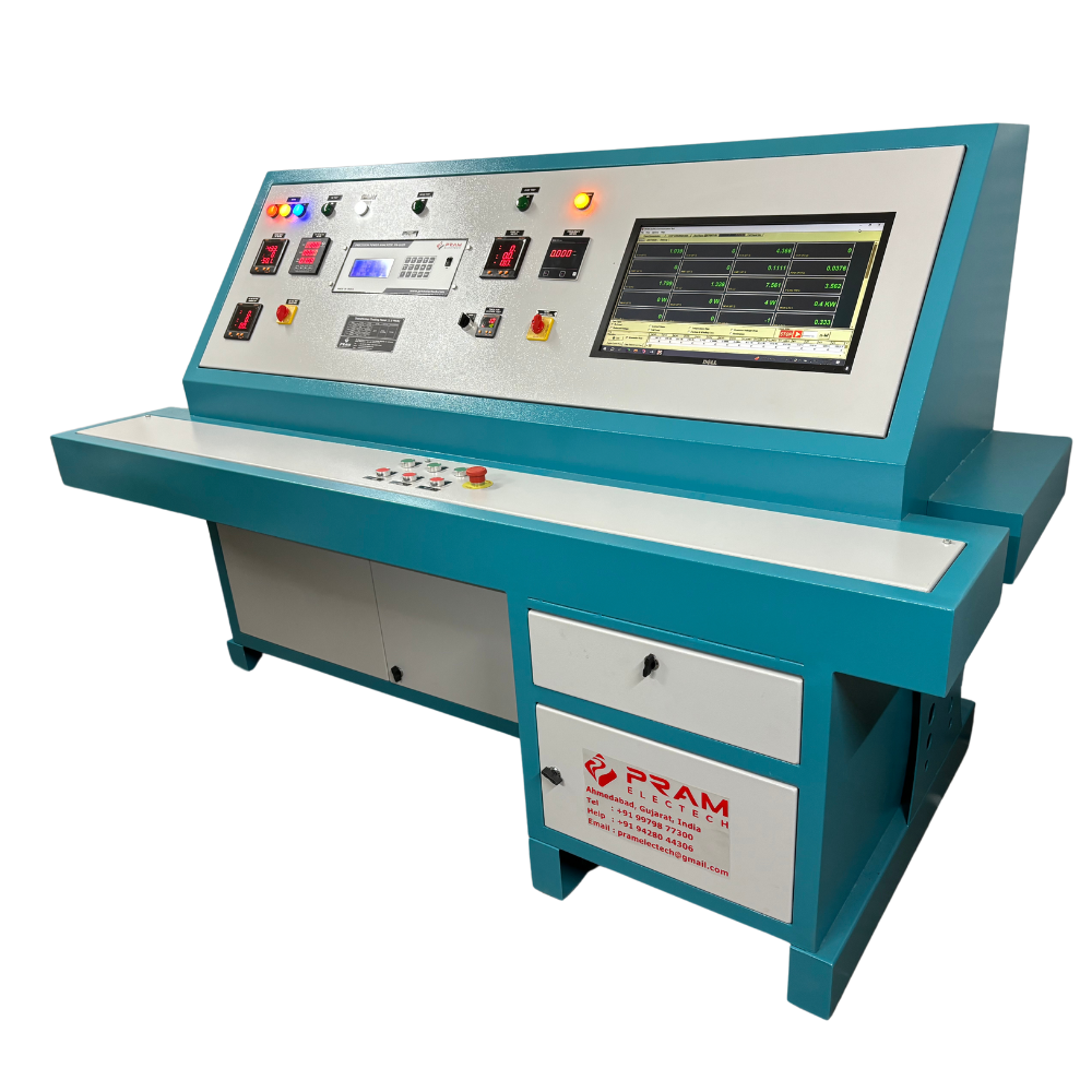
Image disclaimer: For identification and illustration only. It may show a product by another manufacturer and may not depict the exact item described; it is not a statement of any product’s quality, approval or performance. Third-party image and trademark rights belong to their owners. See full notice.
What Is It?
A Transformer Tester is a multifunctional test instrument designed specifically to assess the condition and performance of isolating transformers used in AGL series circuits. These transformers are critical components that provide electrical isolation between the primary series circuit and individual light fixtures. The tester evaluates:
- Turns Ratio: Verifies the transformer's voltage transformation ratio (typically 1:1 or step-down for LED fixtures).
- Winding Resistance: Measures primary and secondary DC resistance to detect open circuits, shorted turns, or high-resistance connections.
- Excitation Current: Assesses the magnetizing characteristics and detects core saturation or shorted turns.
- Insulation Resistance: Measures insulation between windings and between windings and ground.
- Polarity: Confirms correct phase relationship for proper transformer operation.
Modern transformer testers are portable, microprocessor-controlled instruments that provide rapid, accurate measurements with data storage and reporting capabilities. They are essential for commissioning new transformers, preventive maintenance, and fault diagnosis.
Purpose & Function
The transformer tester exists because an isolating transformer's failure modes — a shorted turn, degraded insulation, a shifted turns ratio — often aren't visible from the outside and won't show up on a basic continuity check, yet any one of them can compromise the very isolation and fault-tolerance the transformer exists to provide across the whole series loop. By directly measuring the electrical characteristics that define a healthy transformer, the tester can catch a unit that's degrading before it fails outright and takes its fixture, or worse, part of the loop, out of service.
This matters especially at commissioning, when a newly installed transformer needs to be verified as sound before it's buried or sealed into an inaccessible location, since a fault caught at that stage is a simple swap, while the same fault discovered after installation may mean an unplanned excavation or an in-service failure during live operations.
Where Is It Used?
Transformer testers are used throughout the AGL transformer lifecycle:
- Factory Acceptance Testing (FAT): Verifying transformer specifications before shipment from the manufacturer.
- Site Commissioning: Testing transformers after installation to ensure they meet performance requirements.
- Preventive Maintenance: Periodic testing to detect gradual degradation due to thermal stress, moisture ingress, or insulation aging.
- Fault Diagnosis: Identifying failed or degraded transformers that cause lighting outages or circuit imbalances.
- Post-Repair Verification: Confirming that re-wound or repaired transformers are functioning correctly.
- Asset Management: Building a database of transformer test results to predict failures and plan replacements.
Testing is performed on de-energized circuits, with the transformer isolated from the series loop.
Storage & Handling
Test leads, clip sets, and any adapters specific to different transformer terminal configurations are kept organised in the instrument's case, since a missing or mismatched adapter is a common reason for a test being deferred in the field. The instrument is stored within its rated temperature and humidity range, with batteries maintained per the manufacturer's guidance so the unit is ready to deliver its test signals without a delay for charging. Given that this tester is often used to build a long-term database of transformer health for asset management, it's kept on a consistent calibration schedule so measurements taken at different times and by different technicians remain directly comparable. The unit is protected from moisture and dust during transport between field locations, particularly when testing is carried out at transformers sited in pits or handholes.
How Does It Work?
A transformer tester operates by applying known electrical signals to the transformer windings and measuring the response. Key measurement principles include:
- Turns Ratio Measurement: The tester applies a low AC test voltage to the primary winding and measures the induced voltage on the secondary. The primary-to-secondary voltage ratio is calculated and compared to the nameplate value — most AGL series isolating transformers are 1:1, since both sides of the loop are designed around the same 6.6A (or 20A) constant-current rating, but step-down ratios exist for some LED interface units.
- Winding Resistance: A precision DC current is passed through each winding, and the voltage drop is measured to calculate resistance using Ohm's Law. This detects high-resistance connections or open circuits.
- Excitation Current: The tester applies a reduced AC voltage and measures the magnetizing current. Abnormal currents indicate core problems or shorted turns.
- Insulation Resistance: A high DC voltage (500V or 1000V) is applied between windings and to ground, measuring leakage current to calculate insulation resistance.
- Polarity Test: A DC pulse is applied to the primary, and the secondary polarity is checked to ensure correct phase relationship.
Advanced testers perform all measurements automatically, display results on a clear LCD screen, and store data for trend analysis and reporting. Some models include Bluetooth connectivity for wireless data transfer.
System Architecture & Control Logic
A transformer tester is really three test generators sharing one set of terminals and one control sequence. The MCU steps through excitation, insulation, and polarity tests automatically rather than requiring the operator to reconnect leads for each: it first applies a reduced AC voltage across the winding and measures the magnetising current with a precision current sense stage, comparing the result against a stored expected range for the transformer type to flag core or shorted-turn problems. It then switches internal relays to isolate the AC excitation path and instead drives the same terminals from a high-voltage DC generator to run the insulation resistance test between windings and to ground, reusing the same leakage-current-sensing architecture found in a dedicated insulation tester. Finally, it switches again to a low-energy DC pulse source and reads the induced polarity on the secondary through a fast comparator, checking the phase relationship against the expected dot convention. Because all three front ends are relay-switched into the same measurement and display pipeline, the operator sees one continuous automatic sequence and a single pass/fail summary rather than three separate instrument set-ups.
Signal Injection & Measurement Paths
Physical Construction
A transformer tester is built as a portable, rugged instrument housed in an impact-resistant case, with internal circuitry combining a variable AC test voltage source, a DC insulation resistance test circuit, and precision measurement electronics for turns ratio, winding resistance, and excitation current, all isolated from each other to protect the sensitive measurement stages from the higher test voltages generated elsewhere in the instrument. Test leads are heavy-duty, appropriately insulated for the instrument's maximum output voltage, with clip or probe terminations designed to make a secure connection to a transformer's primary and secondary leads in the field, often within a cramped base can. The front panel houses a backlit LCD display presenting both numerical results and graphical waveform or trend data, along with controls for selecting test voltage, frequency, and test mode. A rechargeable battery pack powers the unit for field use away from mains power, and the case includes a carrying strap or holster along with a protective boot suited to use around wet or muddy base can installations.
Technical Parameters
| Parameter | Typical Value |
|---|---|
| Test Voltage (AC) | 0 – 250V (adjustable) |
| Test Voltage (DC) | 500V, 1000V (insulation resistance) |
| Turns Ratio Range | 0.8 – 2.0 (accuracy ±0.1%) |
| Resistance Range | 0.01 Ω – 2000 Ω |
| Resistance Accuracy | ±0.5% of reading |
| Excitation Current Range | 0 – 10 A AC |
| Insulation Resistance Range | 1 MΩ – 10 GΩ |
| Test Frequency | 50Hz or 60Hz (selectable) |
| Display | LCD with backlight, numerical and graphical |
| Data Storage | 500+ test records with time/date stamp |
| Interface | USB, Bluetooth, or SD card |
| Power Supply | Rechargeable Li-ion battery or AC adapter |
| Safety Rating | CAT III 600V |
| Operating Temperature | 0°C to +50°C |
| Standards Compliance | IEC 61823, IEEE C57.12.90/.91, IEC 61010-1 |
Electrical Requirements
| Requirement | Typical Value |
|---|---|
| Power Supply | Rechargeable Li-ion battery or AC adapter |
| Test Output Voltage | Up to 250V AC / 1000V DC on test terminals — treat as a live source during testing |
| Excitation Output | Up to 10A AC on the excitation current terminals during turns-ratio/load tests |
| Input Protection | CAT III 600V rated test leads and terminals |
| Earthing/Grounding | Chassis bonded to test lead reference; connect the unit-under-test's own earth per test procedure |
| Data/Charging Interface | USB, Bluetooth, or SD card, isolated from the high-voltage test circuit |
Applicable Standards
IEC 61823
AGL series transformers – performance and test requirements
IEEE C57.12.90 / .91
Standard test codes for liquid-immersed (.90) and dry-type (.91) power transformers
IEC 61010-1
Safety requirements for electrical test and measurement equipment
FAA AC 150/5345-47
Specification for series-to-series isolation transformers for airport lighting
FAA AC 150/5340-26
Maintenance of airport visual aid facilities – testing practices
Testing & Commissioning
Visual & Physical Inspection
Receipt InspectionCheck the instrument on receipt for case damage and confirm the lead, clip, and adapter set is complete for the transformer terminal configurations it will be used on.
Calibration Verification Against Reference Standard
Calibration VerificationCompare the instrument's excitation, insulation, and polarity test results against a reference standard and confirm they fall within the manufacturer's accuracy specification.
Lead & Adapter Set Continuity Check
Functional AcceptanceConfirm every lead and adapter combination is continuous and correctly identified, since a missing or mismatched adapter is a common reason a field test gets deferred.
Known-Transformer Reference Test
Functional AcceptanceTest a known-good reference transformer and confirm the instrument correctly reports its turns ratio, magnetising current, and insulation condition.
Documentation & Certification Sign-off
Final AcceptanceRecord calibration results and next due date on the instrument's calibration certificate before it is released for field use.
Inspection & Maintenance
Lead Connection Check
Before each useVerify correct test lead connections to avoid measurement errors from incorrect wiring.
Calibration Check
AnnualVerify readings against a certified reference and recalibrate if drift exceeds tolerance.
Temperature Compensation Check
Before each useRecord ambient or winding temperature and apply the appropriate correction to resistance readings.
Moisture / Insulation Cross-Check
Per testCross-check resistance readings against insulation test results to help rule out moisture ingress.
Common Field Issues
Incorrect Test Lead Connections
Incorrect connection of test leads (e.g., swapping primary and secondary) can produce erroneous ratio readings and potentially damage the tester. Always verify terminal identification and use color-coded leads.
Temperature Effects on Resistance
Winding resistance is temperature-dependent. For accurate comparison, readings should be corrected to a reference temperature (typically 20°C) using standard temperature coefficients.
Moisture in Transformer
Moisture ingress can cause low insulation resistance and high excitation current. If detected, the transformer should be dried (e.g., in an oven) and retested before return to service.
Troubleshooting Guide
Erratic or Inconsistent Turns-Ratio Readings
Insulation Resistance Reads Unexpectedly Low
Excitation Current Reading Abnormally High
Tester Fails to Power On or Display Shows an Error
Failure Modes & Root Causes
Test Lead / Clip Contact Degradation
Internal Reference Calibration Drift
Excitation Source Fault
Battery / Power Failure
Safety & Operational Notes
Isolate the Transformer Under Test
Electrical SafetyDe-energise and lock out the CCR and verify zero energy at the transformer before connecting the tester; never connect a transformer tester to a transformer that is still part of a live series loop.
Instrument Calibration Currency
ComplianceConfirm the tester's calibration certificate is current before relying on its readings for acceptance testing or fault diagnosis; an out-of-calibration instrument can mask a genuine transformer fault.
Correct Test Lead Connection
Electrical SafetyConnect test leads to the correct primary and secondary terminals before initiating a test, since some test functions (such as insulation resistance) apply a test voltage that can damage the transformer or the tester if miswired.
Insulation Test Voltage Awareness
Personnel SafetyInsulation resistance tests apply an elevated DC test voltage to the winding; keep clear of the transformer terminals during the test and allow any residual charge to bleed off before disconnecting the leads.
PPE & Grounding
Personnel SafetyUse insulated tools and appropriate PPE when connecting or disconnecting test leads, and confirm the tester and transformer case are bonded/grounded per the electrical design during testing.
Tester Battery & Self-Test
OperationalRun the instrument's self-test and check its battery condition before a test session, since a low battery or an uncalibrated internal reference can produce misleading readings without an obvious fault indication.
Record Results Against Baseline
ComplianceLog test results against the transformer's commissioning baseline or the manufacturer's acceptance criteria, not against a generic pass/fail threshold, so a genuine drift in performance is caught early.
Restore to Compliant State
ComplianceDo not return a transformer to service on the strength of a tester reading alone if the result is marginal or inconsistent with prior tests; investigate further before closing out the work order.
Engineering & Expert Notes
Let the Transformer Cool Before Retesting
TechniqueInsulation resistance readings taken on a transformer that is still warm from recent service tend to read lower than the true cold value; where a reading is borderline, let the unit cool to ambient and retest before condemning it as a failure.
Trend, Don't Just Pass/Fail
TroubleshootingA single insulation resistance reading that clears the acceptance threshold can still represent a transformer on a steady downward trend. Keep a running log per serial number so a slow decline gets flagged for replacement before it becomes a field fault during a live run.
Moisture Skews Readings More Than Winding Damage
DiagnosticsLow insulation resistance on a field-pulled transformer is more often surface moisture or condensation inside the housing than actual winding insulation breakdown. Where practical, dry the unit and retest before writing it off, since a false condemnation wastes a serviceable transformer.
Turns Ratio Drift Signals Shorted Turns Early
DiagnosticsA turns ratio test that has drifted slightly from the nameplate or baseline value, even while the transformer still "passes" on a simple continuity check, is often the earliest indicator of shorted turns developing under the potting compound. Treat drift as a leading signal, not noise.
Match Test Voltage to the Transformer Class
ElectricalApplying a generic insulation test voltage across every transformer regardless of its rated class can stress a lower-voltage isolation transformer beyond its design margin. Confirm the correct test voltage for the specific transformer class before running the test, not just the tester's default setting.
Keep a Per-Serial Test History, Not Just a Site Log
ProcessTransformers get swapped between circuits and even between airfields during maintenance. Tying test results to the transformer's serial number rather than only its installed location preserves the trend data that actually predicts failure, even after the unit is relocated.
Related Components
Frequently Asked Questions
Short answers about AGL transformer testers: measurements, use cases, specifications, standards and calibration.
Q1What is an AGL transformer tester?
A transformer tester is a portable, microprocessor-controlled instrument that evaluates the condition and performance of isolating transformers in AGL series circuits. It measures turns ratio, winding resistance, excitation current, insulation resistance and polarity to detect faults and verify performance.
Q2Why can't a continuity check replace a transformer tester?
An isolating transformer's failure modes, such as a shorted turn, degraded insulation or a shifted turns ratio, often aren't visible from outside and won't show on a basic continuity check. Any of them can compromise the isolation and fault tolerance the transformer provides across the series loop.
Q3What does a transformer tester measure?
Turns ratio (compared with the nameplate value), primary and secondary DC winding resistance, excitation (magnetising) current, insulation resistance between windings and to ground, and polarity. Most AGL series isolating transformers are 1:1, though step-down ratios exist for some LED interface units.
Q4When is a transformer tester used?
It is used for factory acceptance testing, site commissioning, preventive maintenance, fault diagnosis, post-repair verification of re-wound units, and building a test-result database for asset management. Testing is performed on de-energised circuits with the transformer isolated from the series loop.
Q5Why test a transformer at commissioning?
A fault caught before the transformer is buried or sealed into an inaccessible location is a simple swap. The same fault found after installation may mean an unplanned excavation or an in-service failure during live operations.
Q6What are typical transformer tester specifications?
Typical values are AC test voltage of 0 to 250 V, DC insulation test voltage of 500 V or 1000 V, turns ratio range 0.8 to 2.0 (±0.1%), resistance range 0.01 Ω to 2000 Ω (±0.5%), and insulation resistance range 1 MΩ to 10 GΩ. It usually stores 500+ records and is rated CAT III 600 V.
Q7Which standards apply to transformer testers and transformer testing?
The main references are IEC 61823, IEEE C57.12.90 and C57.12.91, IEC 61010-1 (safety of test equipment), FAA AC 150/5345-47 (series isolation transformers) and FAA AC 150/5340-26 (maintenance of airport visual aid facilities). Always verify the current edition.
Q8How often should a transformer tester be calibrated and checked?
Verify readings against a certified reference and recalibrate annually if drift exceeds tolerance. Check lead connections and record ambient or winding temperature before each use, and cross-check resistance readings against insulation results on each test.
Q9Why do winding resistance readings need temperature correction?
Winding resistance depends on temperature, so for accurate comparison readings should be corrected to a reference temperature, typically 20°C, using standard temperature correction factors.
Q10What are the common transformer testing mistakes and moisture problems?
Swapping primary and secondary test leads gives erroneous ratio readings and can damage the tester, so verify terminal identification first. Moisture ingress in a transformer causes low insulation resistance and high excitation current. If detected, the transformer should be dried and retested before return to service.
Go Beyond the Component. Understand the Complete AGL System.
You have explored the component. Now understand how it works within the complete Airfield Ground Lighting system.
Learn AGL from fundamentals to design, installation, testing, photometry, commissioning, maintenance and troubleshooting through structured technical training at Precision AGL Academy.
Build practical knowledge. Understand the circuit. Read the standards. Troubleshoot with confidence.
Your next step in AGL starts here.
Need expert guidance on transformer tester selection or interpreting test results?
Precision AGL Academy provides advice on tester selection, test procedures, and condition assessment of AGL isolating transformers.
Follow the Academy
Important Notice, Disclaimer & Limitation of Liability
Please read before relying on any content on this page.
- Purpose and intended users. This page on Transformer Tester is an independent educational and informational reference for competent, suitably trained and authorised airfield ground lighting (AGL) and aerodrome electrical personnel. It is not professional engineering, legal or regulatory advice, and using it does not create any professional or client relationship.
- Safety. Work on series circuits, constant current regulators (CCRs), isolating transformers, cables, connectors and lighting equipment can be fatal. Always apply the aerodrome’s permit-to-work and isolation/LOTO procedures, prove dead, use correctly rated instruments and PPE, and follow the manufacturer’s instructions. Nothing here authorises work on live equipment or the bypassing of any safety device or interlock.
- Aviation operations. Nothing here authorises installation, modification, energisation, adjustment, return to service, a change of operating category (CAT I/II/III), a NOTAM or any aerodrome certification or approval decision. These rest with the aerodrome operator, the air navigation service provider and the competent regulator.
- Specifications, ratings and typical values. Descriptions, parameters, ratings, dimensions, photometric values, wattages, service lives, maintenance tasks and intervals, failure modes, certifications (for example CE, FCC, UL or IEC marks) and part or type designations are general, typical and indicative. They may not match any particular product, make, model or version, and they are not a datasheet, design, specification, selection, sizing, procurement or acceptance criterion. The manufacturer’s current documents, the approved design and the project specification prevail.
- Standards and regulations. References to ICAO, FAA, IEC, IEEE, ISO, BIS, DGCA and other standards are paraphrased summaries for orientation only. They may be incomplete or out of date, and standards are revised from time to time. Consult the current official editions. Following this content does not guarantee compliance with any law, standard or regulatory approval, and the regulator’s requirements always prevail.
- No warranty. Content is provided “as is” and “as available”, without warranty of any kind, express or implied, including accuracy, completeness, currency or fitness for a particular purpose. Real installations differ in design, equipment make and model, age and condition.
- Limitation of liability. To the fullest extent permitted by applicable law, Precision AGL Academy, Precision AGL Solutions and their owners, authors and contributors are not liable for any injury, death, loss, damage, downtime, penalty or regulatory consequence, whether direct or indirect, arising from the use of, reliance on, or inability to use this content. Nothing in this notice excludes or limits any liability that cannot lawfully be excluded or limited.
- Independence, brands and no endorsement. This is an independent publication. It is not affiliated with, sponsored by or endorsed by ICAO, the FAA, the IEC, DGCA, AAI, any airport, regulator, supplier or equipment manufacturer. Third-party names, product designations, standard designations and trademarks (including Megger®, Siemens, Eaton, Crouse-Hinds, ADB SAFEGATE, Fluke, ABB and Honeywell) belong to their respective owners and are used only for identification and description. Mention of a brand, product or supplier is not a recommendation, and we do not sell, supply or quote for any component described.
- Images and third-party content. Images and illustrations are shown to help identify the type of component. They may show products of various manufacturers, may not depict the exact item described, and are not a statement about any product’s quality, approval or performance. Copyright and trademarks in third-party images, logos and photographs belong to their respective owners and are not claimed as ours. If you are a rights holder and want an image removed, replaced or credited, email precisionaglsolutions@gmail.com with the page address and we will act promptly.
- Training and services. Mentions of training, courses, consultation, advice, selection, installation, calibration or other support, including the “Learn…Certify” pathway, describe learning stages and are not an offer, quotation, tender or promise of any result. Contacting us or our replying creates no engagement or duty of care; an engagement exists only under a written agreement. We are not a regulator or certification body, and completing any course or reading this content is not a certification, accreditation or authorisation to work on any aerodrome.
- Copyright, privacy and corrections. © 2026 Precision AGL Academy. All rights reserved. Text, structure, compilations and diagrams may be viewed for personal reference and internal training only; any other copying, republication or commercial use needs our written permission. If you email, telephone or message us, we use your details only to respond and handle your matter, in line with applicable Indian law including the Digital Personal Data Protection Act, 2023; please do not send confidential or security-sensitive information. To display this page your browser requests fonts, icons and images from third-party servers, which receive your IP address and browser details under their own policies. Content is reviewed periodically with no obligation to update. To report an error, safety concern or rights issue, write to precisionaglsolutions@gmail.com.