Wireless Sensor
A compact, battery-powered or energy-harvesting device that monitors critical parameters of AGL equipment and transmits data wirelessly to an IoT Gateway or cloud platform. Wireless sensors enable cost-effective, scalable condition monitoring of airfield lighting systems without the need for extensive cabling.
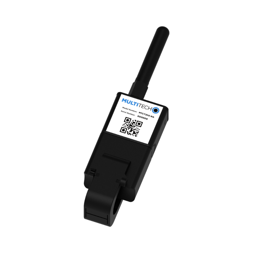
Image disclaimer: For identification and illustration only. It may show a product by another manufacturer and may not depict the exact item described; it is not a statement of any product’s quality, approval or performance. Third-party image and trademark rights belong to their owners. See full notice.
What Is It?
A Wireless Sensor is a self-contained monitoring device that measures physical or electrical parameters (current, voltage, temperature, vibration, humidity, etc.) and transmits the data over a wireless network (LoRa, Zigbee, NB-IoT, Wi-Fi, or Bluetooth). In AGL applications, these sensors are deployed on:
- Lighting Fixtures: Monitoring current, temperature, and lamp status to detect failures early.
- Isolating Transformers: Measuring primary and secondary current, and winding temperature.
- CCRs and Power Equipment: Monitoring load current, ambient temperature, and vibration.
- Cable Systems: Detecting current imbalance or earth leakage using clamp-on current sensors.
- Environmental Conditions: Tracking ambient temperature, humidity, and precipitation near critical equipment.
Wireless sensors reduce installation costs, enable retrofitting of existing infrastructure, and provide real-time visibility into the health of AGL systems, supporting predictive maintenance and operational efficiency.
Purpose & Function
The wireless sensor's purpose is to extend the same current, temperature, or vibration monitoring available on smart fixtures and transformers to equipment and locations where running new cabling would be impractical or prohibitively expensive — making retrofit monitoring of existing airfield infrastructure genuinely feasible rather than something that only applies to newly installed equipment. Its long battery life and low-power wireless transmission exist specifically so it can be installed and largely forgotten for years, providing the same early-warning visibility into equipment health as a wired sensor without requiring trenching, conduit, or a hard-wired power supply. This is what allows an airport to add condition monitoring incrementally across its existing lighting circuits rather than needing a wholesale infrastructure upgrade to gain that visibility.
Where Is It Used?
Wireless sensors are deployed across the airfield where monitoring is needed but cabling is impractical:
- Runway and Taxiway Lighting: Monitoring individual edge, centreline, and threshold lights for current and temperature anomalies.
- Isolating Transformers: Monitoring transformer health to predict failures before they cause circuit outages.
- CCR Rooms: Environmental monitoring (temperature, humidity) of equipment shelters.
- Approach Lighting: Monitoring barrette and flashing light status for approach systems.
- Obstruction Lighting: Ensuring beacons and obstruction markers are operational.
- PAPI and VASI Systems: Verifying correct lamp current and tilt angle.
- Remote Equipment: Monitoring wind cones, VDGS, and other standalone systems.
Sensors are typically mounted inside or adjacent to the equipment being monitored, with antennas positioned for optimal wireless coverage.
Installation & Location
The sensor is fixed to (or placed directly inside) the fixture, transformer, or shelter it monitors, using adhesive, a magnetic base, or a small bracket, positioned so its measurement point (current clamp, temperature probe, or humidity element) sits in direct contact with or close proximity to what it's sensing. Because there's no cabling to a control room, siting is driven mainly by radio performance: the unit is placed to keep line-of-sight or minimal obstruction to the nearest gateway, clear of dense metal enclosures that would attenuate the signal, and a coverage check is carried out at installation before the sensor is sealed into its final position. Battery-powered units are sited for reasonable access at replacement intervals, and the sensor's location and parent asset are registered on the monitoring platform so its readings map to the correct piece of equipment.
How Does It Work?
A wireless sensor operates through a combination of sensing, processing, and communication. The device includes:
- Transducer/Sensor Element: Converts the physical parameter (current, temperature, vibration) into an electrical signal (e.g., Hall effect for current, thermistor for temperature).
- Signal Conditioning: Amplifies, filters, and digitizes the signal using an analog-to-digital converter (ADC).
- Microcontroller: Processes the data, performs local calculations, and determines if alerts need to be triggered.
- Wireless Transceiver: Transmits the data using a low-power protocol (LoRa, Zigbee, NB-IoT, etc.) to a nearby IoT Gateway or directly to the cloud.
- Power Source: Typically a long-life battery (3-10 years) or energy harvesting (solar, inductive) to ensure maintenance-free operation.
- Enclosure: Rugged, weatherproof housing (IP67/IP68) to withstand airfield environments.
The sensor typically operates in a low-duty cycle mode, waking up periodically (e.g., every 5 minutes) to take a measurement, transmit data, and then returning to deep sleep to conserve battery. Some sensors also support event-driven transmission when a threshold is exceeded.
System Architecture & Control Logic
Battery life over years, not raw performance, is what shapes this device's control logic. For most of its life the MCU sits in a deep-sleep state drawing microamps, woken only by one of two triggers: a real-time-clock interrupt on a fixed schedule (e.g., every 5 minutes) or an interrupt from the sensing element itself when a configured threshold is crossed. On waking, the MCU powers up the sensor and analog front end just long enough to take and condition a reading, then powers up the radio transceiver, forms a small data packet, and transmits it to the nearest gateway using whatever low-power protocol the sensor is built around (LoRa, Zigbee, or NB-IoT) — the radio is the single largest power draw in the system, so the firmware minimises its on-time rather than the sensing itself. If the gateway does not acknowledge receipt, the MCU can buffer the reading and retry on the next cycle rather than holding the radio on to wait. Once transmission (or buffering) completes, every subsystem is powered back down and the MCU returns to sleep until the next scheduled or threshold-triggered wake, a pattern that is what allows a coin-cell or small battery pack to last several years in the field.
Wake, Measure, Transmit, Sleep
Physical Construction
The sensor node is built into a compact, sealed polymer or die-cast enclosure rated IP67/IP68, sized to house the sensing element (current transformer, thermocouple, accelerometer, or humidity/pressure element), signal-conditioning circuitry, wireless radio module, and battery pack within a single weatherproof shell. The enclosure incorporates a moulded antenna window or external whip antenna positioned to maximise radio range while remaining protected from physical damage, and cable glands or potted cable entries seal the connection to the sensed conductor or mounting point against moisture ingress. Mounting features, such as DIN-rail clips, magnetic bases, or bolt-on brackets, are integrated into the housing to suit installation on cables, conduits, or fixture bodies without additional hardware. The battery compartment is designed for field replacement without breaking the main enclosure seal, and the overall unit is built to withstand the wide operating temperature range and vibration typical of outdoor, unattended AGL monitoring points.
Technical Parameters
| Parameter | Typical Value |
|---|---|
| Measurement Parameters | Current (AC/DC), Voltage, Temperature, Vibration, Humidity, Pressure |
| Current Sensing Range | 0 – 10A, 0 – 100A, or 0 – 1000A (depending on model) |
| Temperature Range | -40°C to +125°C |
| Measurement Accuracy | ±1% to ±3% of full scale |
| Wireless Protocol | LoRaWAN, Zigbee, NB-IoT, LTE-M, Wi-Fi, or Bluetooth 5.0 |
| Frequency Band | 868 MHz, 915 MHz, 2.4 GHz (regional) |
| Transmission Range | Up to 10 km (LoRa line-of-sight) |
| Data Transmission Interval | 1 minute to 24 hours (configurable) |
| Battery Life | 3 – 10 years (depending on interval and protocol) |
| Battery Type | Lithium (primary) or rechargeable with energy harvesting |
| Ingress Protection | IP67 or IP68 |
| Operating Temperature | -40°C to +85°C |
| Dimensions | 50mm x 50mm x 30mm (typical) |
| Standards Compliance | FCC Part 15, ETSI EN 300 220, RoHS, REACH |
Electrical Requirements
| Requirement | Typical Value |
|---|---|
| Circuit Position | Standalone battery-powered sensor; may include current-sensing clamp inputs |
| Power Supply | Internal battery (lithium primary or rechargeable with energy harvesting) |
| Battery Life | 3 – 10 years (depending on interval and protocol) |
| Current Sensing Input | 0 – 10A, 0 – 100A, or 0 – 1000A clamp/CT input (model dependent) |
| Isolation | Battery operation and CT-based sensing keep the unit galvanically isolated from the monitored circuit |
| Fault Protection | Low-battery and communication-loss alarms reported to the host system |
Applicable Standards
FCC Part 15
Radio frequency devices (USA)
ETSI EN 300 220
Short Range Devices (SRD) – radio equipment
LoRaWAN Specification
LPWAN protocol for IoT applications
IEC 60529
Degrees of protection provided by enclosures (IP Code)
Installation Requirements
Sensing Point Contact
MechanicalFix the sensor to the fixture, transformer, or shelter it monitors using adhesive, a magnetic base, or a small bracket, positioning the measurement point in direct contact with or close proximity to what it's sensing.
Radio Coverage Check
NetworkCarry out a coverage check at the proposed location before sealing the sensor into its final position, confirming line-of-sight or minimal obstruction to the nearest gateway clear of dense metal enclosures.
Battery Access & Replacement Planning
MechanicalSite battery-powered units for reasonable access at replacement intervals rather than in locations that would require special access equipment.
Platform Registration
DocumentationRegister the sensor's location and parent asset on the monitoring platform so its readings map to the correct piece of equipment.
Pre-Commissioning Sign-off
DocumentationRecord sensor position, coverage check result, and platform registration as-built before the sensor is relied on for monitoring.
Testing & Commissioning
Power-Up & Battery Verification
Pre-EnergisationConfirm the sensor powers up correctly and that battery voltage or energy-harvesting charge is adequate for the planned deployment interval before installation.
Sensor Calibration / Accuracy Check
Pre-EnergisationCompare the sensor's current, voltage, temperature, vibration, humidity, or pressure reading against a calibrated reference, confirming accuracy is within the stated ±1–3% specification.
Wireless Link & Range Test
EnergisationConfirm the sensor establishes and maintains a reliable link over LoRaWAN, Zigbee, NB-IoT, LTE-M, Wi-Fi, or Bluetooth at the installed location and expected range.
Data Transmission Interval & Payload Verification
EnergisationVerify the configured transmission interval and confirm the received payload at the gateway or head-end matches the sensor's measured values.
Enclosure IP Rating Verification
Final AcceptanceConfirm the sealed enclosure meets its rated IP67/IP68 ingress protection before the unit is left in its final, often inaccessible, field location.
Documentation & As-Built Sign-off
Final AcceptanceRecord calibration, link-quality, and transmission-interval verification alongside as-built sensor position and gateway pairing in the commissioning dossier for handover.
Inspection & Maintenance
Battery / Power Check
Semi-annualVerify battery voltage or energy-harvesting output against expected levels, replacing units approaching end of life before they drop offline.
Sensor Calibration Verification
AnnualCheck sensor readings against a known reference for critical parameters such as current or temperature to catch drift early.
RF Signal Strength Survey
Semi-annualMeasure signal strength and packet loss across the network to detect degraded coverage from new structures or interference.
Gateway & Repeater Inspection
AnnualCheck antenna placement, connections, and health of gateways and repeaters that extend network coverage across the airfield.
Enclosure & Seal Inspection
AnnualInspect sensor housings and seals for weather damage that could affect battery life or electronics.
Firmware Update Review
QuarterlyCheck for sensor and gateway firmware updates that improve reliability or add temperature-compensated power management.
Common Field Issues
RF Interference and Signal Attenuation
Airfield structures, metal enclosures, and electromagnetic noise can degrade wireless signal strength. Proper antenna placement and using a gateway with multiple antennas or repeaters is essential for reliable coverage.
Battery Life Degradation
Extreme temperatures (especially high heat) can reduce battery life. Use of industrial-grade batteries and temperature-compensated power management is recommended. Some sensors support energy harvesting (solar, thermal) to extend lifetime.
Sensor Drift and Calibration
Over time, sensor elements can drift, affecting measurement accuracy. Periodic calibration or verification against known references is required, especially for critical parameters like current and temperature.
Troubleshooting Guide
Sensor Not Reporting / Dropped from Network
Weak or Intermittent Signal Strength
Battery Draining Faster Than Expected
Reported Values Drift from Known-Good Reference
Failure Modes & Root Causes
Battery Depletion
RF Signal Degradation
Sensor Element Drift
Excessive Power Consumption
Safety & Operational Notes
Battery Handling & Disposal
Personnel SafetyHandle and dispose of the sensor's battery according to the manufacturer's safety data sheet, and never puncture, crush, or expose it to excessive heat when replacing it in the field.
RF Interference Awareness
OperationalSite and orient the sensor to avoid known sources of RF interference where practical, and be aware that dense metal structures or other wireless equipment nearby can degrade its link reliability.
Airside Work Coordination
OperationalCoordinate placement or servicing of sensors mounted within the movement area with ATC/airside operations, particularly where a ladder, vehicle, or extended presence near active pavement is required.
Weatherproof Housing Care
OperationalConfirm the housing seal is correctly reinstated after opening a sensor for battery replacement or servicing, since moisture ingress is a common cause of sensor element drift and premature failure.
PPE for Field Servicing
Personnel SafetyWear appropriate PPE for the mounting location, including fall protection for elevated sensors and hi-vis clothing for sensors within the movement area.
Engineering & Expert Notes
Battery Life Is a Reporting-Interval Decision
DesignThe single biggest lever on service life is the reporting interval, not the battery chemistry. Tightening the interval "just to be safe" during commissioning quietly halves the field life and turns into an unplanned battery-swap campaign a year or two later than expected.
A Marginal Link Fails Intermittently, Not Cleanly
TroubleshootingA sensor near the edge of usable signal strength tends to drop packets sporadically rather than going fully offline, which can look like a flaky sensor rather than an RF path problem. Log signal strength over time before swapping hardware; a declining trend usually points to a new obstruction, not a failing unit.
Stagger Battery Replacement, Don't Wait for Failure
MaintenanceLetting every sensor in a batch run to depletion means they tend to fail in a cluster, since they were commissioned around the same time. Track installation dates and proactively rotate batteries on a schedule rather than reacting to a wave of "sensor offline" alerts.
Cold Weather Compounds Two Problems at Once
ReliabilityLow temperature both reduces usable battery capacity and is often when winter operations most need reliable sensor data. Budget extra margin into replacement schedules for sensors in cold-climate deployments rather than using a single battery-life figure across all sites.
Gateway Placement Matters as Much as Sensor Placement
DesignChasing sensor-side fixes for a poor link often overlooks that the gateway or repeater location is the real constraint. A mid-field repeater can resolve link issues across several sensors at once more effectively than relocating each one individually.
Weatherproof Seals Degrade Faster With Frequent Access
DurabilityEvery battery swap is a chance to compromise the housing seal if the gasket isn't inspected and reseated properly. A sensor that needs frequent access due to a short battery life will see more seal-related failures over its life than one serviced rarely, which is worth factoring into the interval-vs-battery-life trade-off.
Frequently Asked Questions
Short answers about wireless sensors for AGL monitoring: protocols, battery life, standards, maintenance and troubleshooting.
Q1What is a wireless sensor in AGL monitoring?
A self-contained device that measures parameters such as current, voltage, temperature, vibration or humidity and transmits the data over a wireless network such as LoRa, Zigbee, NB-IoT, Wi-Fi or Bluetooth.
Q2Why use wireless sensors on an airfield?
They extend current, temperature and vibration monitoring to equipment and locations where running new cabling would be impractical or expensive, making retrofit monitoring feasible.
Q3Where are wireless sensors deployed?
Wherever monitoring is needed but cabling is impractical, including runway and taxiway lighting (current and temperature anomalies) and isolating transformers.
Q4Which wireless protocols and ranges are typical?
LoRaWAN, Zigbee, NB-IoT, LTE-M, Wi-Fi or Bluetooth 5.0 on regional bands of 868 MHz, 915 MHz or 2.4 GHz, with LoRa reaching up to about 10 km line of sight.
Q5What can they measure and how accurately?
Current ranges of 0-10 A, 0-100 A or 0-1000 A depending on model, temperature from -40°C to +125°C, and typical accuracy of ±1% to ±3% of full scale.
Q6How long does the battery last?
Typically 3-10 years depending on transmission interval (1 minute to 24 hours) and protocol, using a lithium primary cell or a rechargeable cell with energy harvesting.
Q7Is the sensor electrically isolated from the monitored circuit?
Battery operation and CT-based current sensing keep the unit galvanically isolated from the monitored circuit.
Q8Which standards apply?
FCC Part 15 (USA radio frequency devices), ETSI EN 300 220 (short range devices), the LoRaWAN specification and IEC 60529 (IP code), with IP67 or IP68 enclosures typical.
Q9How often should wireless sensors be maintained?
Semi-annually for battery and RF signal strength surveys, annually for calibration verification, gateway and repeater inspection and enclosure and seal checks, and quarterly for firmware update review.
Q10Why has a sensor stopped reporting?
Likely causes are a depleted battery, the sensor being out of gateway range, or RF interference from nearby structures. Check the reported battery level and last-seen timestamp on the gateway.
Related Components
Go Beyond the Component. Understand the Complete AGL System.
You have explored the component. Now understand how it works within the complete Airfield Ground Lighting system.
Learn AGL from fundamentals to design, installation, testing, photometry, commissioning, maintenance and troubleshooting through structured technical training at Precision AGL Academy.
Build practical knowledge. Understand the circuit. Read the standards. Troubleshoot with confidence.
Your next step in AGL starts here.
Need expert guidance on wireless sensor selection or deployment for your AGL system?
Precision AGL Academy provides advice on sensor types, wireless protocols, battery life optimization, and data integration for airfield monitoring.
Follow the Academy
Important Notice, Disclaimer & Limitation of Liability
Please read before relying on any content on this page.
- Purpose and intended users. This page on Wireless Sensor is an independent educational and informational reference for competent, suitably trained and authorised airfield ground lighting (AGL) and aerodrome electrical personnel. It is not professional engineering, legal or regulatory advice, and using it does not create any professional or client relationship.
- Safety. Work on series circuits, constant current regulators (CCRs), isolating transformers, cables, connectors and lighting equipment can be fatal. Always apply the aerodrome’s permit-to-work and isolation/LOTO procedures, prove dead, use correctly rated instruments and PPE, and follow the manufacturer’s instructions. Nothing here authorises work on live equipment or the bypassing of any safety device or interlock.
- Aviation operations. Nothing here authorises installation, modification, energisation, adjustment, return to service, a change of operating category (CAT I/II/III), a NOTAM or any aerodrome certification or approval decision. These rest with the aerodrome operator, the air navigation service provider and the competent regulator.
- Specifications, ratings and typical values. Descriptions, parameters, ratings, dimensions, photometric values, wattages, service lives, maintenance tasks and intervals, failure modes, certifications (for example CE, FCC, UL or IEC marks) and part or type designations are general, typical and indicative. They may not match any particular product, make, model or version, and they are not a datasheet, design, specification, selection, sizing, procurement or acceptance criterion. The manufacturer’s current documents, the approved design and the project specification prevail.
- Standards and regulations. References to ICAO, FAA, IEC, IEEE, ISO, BIS, DGCA and other standards are paraphrased summaries for orientation only. They may be incomplete or out of date, and standards are revised from time to time. Consult the current official editions. Following this content does not guarantee compliance with any law, standard or regulatory approval, and the regulator’s requirements always prevail.
- No warranty. Content is provided “as is” and “as available”, without warranty of any kind, express or implied, including accuracy, completeness, currency or fitness for a particular purpose. Real installations differ in design, equipment make and model, age and condition.
- Limitation of liability. To the fullest extent permitted by applicable law, Precision AGL Academy, Precision AGL Solutions and their owners, authors and contributors are not liable for any injury, death, loss, damage, downtime, penalty or regulatory consequence, whether direct or indirect, arising from the use of, reliance on, or inability to use this content. Nothing in this notice excludes or limits any liability that cannot lawfully be excluded or limited.
- Independence, brands and no endorsement. This is an independent publication. It is not affiliated with, sponsored by or endorsed by ICAO, the FAA, the IEC, DGCA, AAI, any airport, regulator, supplier or equipment manufacturer. Third-party names, product designations, standard designations and trademarks (including Megger®, Siemens, Eaton, Crouse-Hinds, ADB SAFEGATE, Fluke, ABB and Honeywell) belong to their respective owners and are used only for identification and description. Mention of a brand, product or supplier is not a recommendation, and we do not sell, supply or quote for any component described.
- Images and third-party content. Images and illustrations are shown to help identify the type of component. They may show products of various manufacturers, may not depict the exact item described, and are not a statement about any product’s quality, approval or performance. Copyright and trademarks in third-party images, logos and photographs belong to their respective owners and are not claimed as ours. If you are a rights holder and want an image removed, replaced or credited, email precisionaglsolutions@gmail.com with the page address and we will act promptly.
- Training and services. Mentions of training, courses, consultation, advice, selection, installation, calibration or other support, including the “Learn…Certify” pathway, describe learning stages and are not an offer, quotation, tender or promise of any result. Contacting us or our replying creates no engagement or duty of care; an engagement exists only under a written agreement. We are not a regulator or certification body, and completing any course or reading this content is not a certification, accreditation or authorisation to work on any aerodrome.
- Copyright, privacy and corrections. © 2026 Precision AGL Academy. All rights reserved. Text, structure, compilations and diagrams may be viewed for personal reference and internal training only; any other copying, republication or commercial use needs our written permission. If you email, telephone or message us, we use your details only to respond and handle your matter, in line with applicable Indian law including the Digital Personal Data Protection Act, 2023; please do not send confidential or security-sensitive information. To display this page your browser requests fonts, icons and images from third-party servers, which receive your IP address and browser details under their own policies. Content is reviewed periodically with no obligation to update. To report an error, safety concern or rights issue, write to precisionaglsolutions@gmail.com.