Auxiliary Relay Cabinet (L-841)
A rugged, weatherproof enclosure housing relays, contactors, and control logic for remote switching and monitoring of AGL lighting circuits. Widely referred to in the field as an "L-841-style" cabinet after FAA's original relay-panel type, the modern Auxiliary Relay Cabinet provides a scalable, field‑deployable interface between the central ALCMS and distributed lighting loads, enabling reliable circuit control, status feedback, and fault detection in airfield environments.
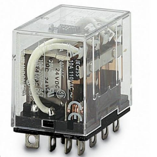
Image disclaimer: For identification and illustration only. It may show a product by another manufacturer and may not depict the exact item described; it is not a statement of any product’s quality, approval or performance. Third-party image and trademark rights belong to their owners. See full notice.
What Is It?
An Auxiliary Relay Cabinet — commonly called an L-841 Relay Cabinet or Remote Relay Cabinet after FAA's original relay-panel type — is a standardised, industrial‑grade enclosure that houses the relay‑based switching and monitoring logic for airfield ground lighting circuits. It is typically installed in remote substations, runway edge cabinets, or equipment shelters, where it acts as the local control hub between the central ALCMS (or PLC) and the field lighting circuits.
Note on terminology: FAA's original L-841 specification (AC 150/5345‑13B) covers a much narrower device — a 20‑relay, DC‑powered pilot relay panel used specifically for Pilot‑Controlled Lighting (PCL) at unstaffed airports, with no networked communications or PLC logic. The industry has since extended the "L‑841" name to the broader family of networked, PLC/CCR‑integrated relay cabinets described on this page. Where strict FAA type‑approval to the 2007 spec is required, confirm the specific cabinet is qualified against AC 150/5345‑13B rather than assuming the features below apply.
The cabinet contains a combination of electromechanical relays, solid‑state contactors, interposing relays, and auxiliary control devices that perform the following functions:
- Circuit Switching: Energising and de‑energising lighting circuits (runway edge, centreline, taxiway, approach) in response to commands from the ALCMS or local control panels.
- Status Monitoring: Providing dry‑contact feedback to the ALCMS indicating the actual state of each circuit (ON/OFF), enabling confirmation that commands have been executed.
- Brightness Step Control: Switching between multiple brightness levels (typically 3 to 5 steps) by selecting the appropriate CCR tap or contactor combination.
- Interlocking & Safety: Implementing hardwired interlock logic to prevent conflicting operations (e.g., preventing a circuit from being energised when maintenance access is required).
- Fault Detection: Monitoring auxiliary contacts of circuit breakers and contactors to detect and report faults such as overloads, short circuits, or contactor failures.
The cabinet is designed for harsh outdoor environments, featuring a robust metallic enclosure (typically stainless steel or powder‑coated mild steel) with an IP66 or NEMA 4X rating, providing protection against dust, water jets, and ice formation. It is equipped with terminal blocks for field wiring, clearly labelled to simplify installation and maintenance, and often includes a local HMI (or status indication panel) for manual override and diagnostics.
Purpose & Function
The L-841 cabinet exists to give the central ALCMS a physical point of execution and confirmation out in the field, since a control command issued from the control room has no real effect until something local actually switches the circuit and reports back that it did so correctly. By combining switching, status feedback, brightness-step control, interlocking, and fault detection in one cabinet, it closes the loop between "the operator asked for this" and "the field confirms this is actually happening," which matters because a command that silently fails to execute is arguably more dangerous than an obvious failure — it gives the false impression that lighting is correctly configured when it isn't. Its hardwired interlock logic serves a distinct purpose within that same cabinet: some safety conditions (like preventing energisation during maintenance access) are critical enough that they need to be enforced at the local hardware level, independent of software or communication links back to the ALCMS that could themselves fail or be delayed.
Where Is It Used?
The L-841 Auxiliary Relay Cabinet is deployed in various locations across the airfield where distributed control of lighting circuits is required, including:
- Remote CCR Substations: Acting as the local switching interface for CCRs, enabling remote control of circuit energisation and brightness selection.
- Runway Edge Lighting Cabinets: Controlling individual runway edge lighting circuits, with status feedback to the ALCMS.
- Taxiway Lighting Nodes: Managing taxiway edge and centreline lighting in specific zones, enabling selective switching for maintenance or operational flexibility.
- Approach Lighting Control Shelters: Providing the switching and interlocking logic for approach light barrettes and sequenced flashing systems.
- Apron & Gate Lighting: Controlling apron floodlights and gate guidance lights, with local override capability for ground crew.
- Isolated Intersection Lighting: Providing independent control of runway‑taxiway intersection lighting, ensuring proper sequencing and interlocking.
- Legacy System Modernisation: Retrofitting to replace obsolete relay logic with a modern, maintainable cabinet while preserving existing field wiring.
Installation & Location
The L-841 cabinet is installed close to the circuits it switches — inside or beside a remote CCR substation, in a runway edge or taxiway lighting cabinet, or in an approach lighting control shelter — so the heavy relay and contactor wiring to the field circuits stays short while a lighter control and feedback cable runs back to the ALCMS or panel commanding it. It's floor- or wall-mounted in a dedicated cabinet with enough internal space and ventilation for its relay bank, and positioned for technician access to individual relays during fault-finding or maintenance. Where it's retrofitted to replace obsolete relay logic, it's installed in the same physical location as the equipment it replaces so the existing field wiring can be reconnected without rerouting cable through the site.
How Does It Work?
The Auxiliary Relay Cabinet operates as a distributed control node, receiving commands from the central ALCMS (or PLC) and translating them into physical switching actions on the field lighting circuits. Key functional aspects include:
- Command Reception: The cabinet receives digital commands from the ALCMS via a communication link (typically serial RS‑485, Modbus, or Ethernet). These commands include circuit ON/OFF requests, brightness step selections, and mode changes.
- Relay Logic Execution: The received commands are processed by the relay logic — either through hardwired relay circuits or a programmable logic controller (PLC) within the cabinet. The logic evaluates interlocks, safety conditions, and sequencing requirements before energising the appropriate output relays.
- Switching Action: The output relays (or contactors) switch the control voltage to the CCRs or directly to the lighting circuit contactors, energising or de‑energising the circuits as commanded. For brightness control, the cabinet selects the appropriate CCR tap or auxiliary contactor to achieve the desired current level (e.g., Step 1 through Step 5).
- Status Feedback: Auxiliary contacts on the relays and contactors provide a dry‑contact status signal back to the ALCMS, confirming that the switching action has been successfully executed. This feedback enables the ALCMS to display the actual circuit state and to detect failures (e.g., a relay that did not change state).
- Fault Monitoring: The cabinet continuously monitors for abnormal conditions, such as contactor failure, loss of control power, or communication loss. These faults are reported to the ALCMS as alarms, enabling rapid intervention.
- Local Override: The cabinet typically includes a local control panel (or pushbuttons) that allows maintenance personnel to manually override the automatic control, enabling testing and troubleshooting without ALCMS involvement.
The cabinet is powered from a dedicated 120/230 VAC supply (or 24 VDC for low‑power versions) and includes surge protection, circuit breakers, and fusing to protect both the cabinet and the field circuits. The internal wiring is colour‑coded and clearly labelled, following standard airfield wiring practices to facilitate troubleshooting.
Command, Feedback Loop & Control Logic
ALCMS Command
ON/OFF, brightness step, or mode change
Command Reception
Via RS-485, Modbus, or Ethernet
Relay Logic
Evaluates interlocks & safety conditions
Switching Action
Relay/contactor selects CCR tap or circuit
Lighting Circuit
Runway, taxiway, or approach lights
Lighting Circuit
Actual energised state
Status Feedback
Dry-contact signal confirms switching
ALCMS Display
Confirms command was executed
Physical Construction
The cabinet is a free-standing or wall-mounted enclosure in stainless steel (304/316) or powder-coated mild steel, gasketed and rated IP66/NEMA 4X so it can be sited outdoors or in an unconditioned equipment room close to the circuits it switches. Inside, contactors or solid-state relays sized to the cabinet's output current rating are mounted on a back-panel or DIN rail, one per controlled circuit, wired through screw- or spring-clamp terminal blocks rated for the heavier AWG 14-8 field cabling typical of lighting circuit feeders. A local HMI — LED indicators, pushbuttons, or an optional touchscreen — is fitted to the door or a front sub-panel for on-site status checks and manual override, while surge arresters on the power and communication lines protect the contactors and any networked controller card from switching transients and induced surges. The cabinet's door is gasketed and secured with cam latches or a lockable handle, and an optional internal heater and thermostat keep condensation and cold-start contactor issues under control in exposed, cold-climate installations.
Technical Parameters
| Parameter | Typical Value |
|---|---|
| Enclosure Type | Free‑standing or wall‑mount, IP66 / NEMA 4X (weatherproof) |
| Enclosure Material | Stainless steel (304/316) or powder‑coated mild steel |
| Number of Output Circuits | 4, 8, 12, 16, or 24 (customisable / expandable) |
| Output Contact Rating | 10A to 30A @ 240 VAC (resistive), 3A to 10A @ 240 VAC (inductive) |
| Brightness Steps | 3‑step, 5‑step, or continuously variable (via analog output) |
| Control Voltage | 120 VAC, 230 VAC, or 24 VDC (field selectable) |
| Communication Interface | RS‑485 (Modbus RTU), Ethernet (Modbus TCP, Profinet), or hardwired discrete I/O |
| Local HMI | LED status indicators, pushbuttons, or touchscreen display (optional) |
| Fault Detection | Contactor auxiliary contacts, undervoltage/overcurrent monitoring |
| Surge Protection | Built‑in surge arresters on power and communication lines |
| Operating Temperature | -25°C to +55°C (with optional heater for cold climates) |
| Storage Temperature | -40°C to +85°C |
| Power Supply | 120/230 VAC ±10%, 50/60 Hz (or 24 VDC for low‑power variants) |
| Power Consumption | 50‑200 W (depending on number of circuits and contactor size) |
| Terminal Type | Screw‑clamp or spring‑clamp terminals, rated for AWG 14‑8 |
| Dimensions (Typical) | 600mm × 800mm × 250mm (H × W × D) for 16‑circuit cabinet |
| Weight | 30‑80 kg (depending on configuration) |
| Certifications | CE, UL, CSA, FCC, IEC 61000‑6‑2 (EMC immunity), FAA AC 150/5345‑13B |
Electrical Requirements
| Requirement | Typical Value |
|---|---|
| Supply Voltage | 120/230 VAC ±10%, 50/60 Hz (or 24 VDC for low-power variants) |
| Power Consumption | 50-200 W (depending on number of circuits and contactor size) |
| Output Contact Rating | 10A to 30A @ 240 VAC (resistive), 3A to 10A @ 240 VAC (inductive) |
| Terminal Wiring | Screw-clamp or spring-clamp terminals, AWG 14-8 |
| Surge Protection | Built-in surge arresters on power and communication lines |
| Earthing/Grounding | Enclosure bonded to earth grid; NEMA 4X/IP66 rated for outdoor installation |
| Fault Protection | Undervoltage/overcurrent monitoring, contactor auxiliary-contact feedback |
Applicable Standards
FAA AC 150/5345‑13B
Specification for L‑841 Auxiliary Relay Cabinet Assembly for Pilot Control of Airport Lighting Circuits (original relay‑panel type)
FAA AC 150/5345‑56B
Specification for L‑890 Airport Lighting Control and Monitoring System (ALCMS) — governs the supervisory system this cabinet interfaces with
IEC 60529
Degrees of protection provided by enclosures (IP code — IP66 rating)
NEMA 250
Enclosures for Electrical Equipment (NEMA 4X rating)
Installation Requirements
Proximate Siting to Switched Circuits
CivilSite the cabinet close to the circuits it switches — a remote CCR substation, runway edge or taxiway lighting cabinet, or approach lighting control shelter — so heavy relay and contactor wiring to the field circuits stays short.
Floor / Wall Mounting with Ventilation Clearance
MechanicalFloor- or wall-mount the cabinet with enough internal space and ventilation for its relay bank, positioned for technician access to individual relays during fault-finding or maintenance.
Field Circuit Wiring to Output Relays
ElectricalWire the heavy relay and contactor connections to the field circuits, keeping this wiring separated from the lighter control and feedback cable running back to the ALCMS or commanding panel.
Retrofit Wiring Continuity
ElectricalWhere retrofitting obsolete relay logic, install the cabinet in the same physical location as the equipment it replaces so existing field wiring can be reconnected without rerouting cable.
Auxiliary Contact Wiring for Fault Feedback
ElectricalWire auxiliary contacts so contactor state correctly reports back to the fault detection circuit or communication interface.
Communication Interface Configuration
NetworkConfigure the RS-485 or Ethernet interface to the ALCMS before the cabinet is placed into service.
Enclosure Sealing & Earth Bonding
MechanicalSeal the weatherproof enclosure and connect the earth bonding point correctly before the cabinet is closed up.
Pre-Energisation Sign-off
DocumentationRecord circuit mapping, contact ratings, and mounting location as-built before the cabinet is energised.
Testing & Commissioning
Power & Control Voltage Check
Pre-EnergisationConfirm supply and control voltage rails are within spec before exercising the cabinet's output relays and contactors.
Output Circuit Verification
EnergisationEnergise each output circuit individually and confirm it switches the correct downstream load at the correct brightness step.
Contactor Auxiliary Contact Test
Final AcceptanceConfirm auxiliary contacts correctly report contactor state back to the fault detection circuit or communication interface.
Undervoltage / Overcurrent Trip Test
Final AcceptanceSimulate an undervoltage or overcurrent condition and confirm the cabinet correctly trips and reports the fault.
Communication Interface Test
Final AcceptanceConfirm the cabinet exchanges status and control data correctly with the ALCMS over its configured RS-485 or Ethernet interface.
Enclosure Seal & Bonding Check
Pre-EnergisationConfirm the weatherproof enclosure seals correctly and the earth bonding point is properly connected before the cabinet is closed up.
Documentation & As-Built Sign-off
Final AcceptanceRecord circuit mapping, contact ratings, and trip-test results in the commissioning dossier for handover.
Inspection & Maintenance
Contactor & Relay Inspection
Semi-annualCheck contactors for discolouration or burnt odour indicating coil overheating, and verify auxiliary interlocking remains functional.
Terminal Torque & Corrosion Check
AnnualRe-torque terminal connections and inspect for corrosion, applying anti-oxidant grease in coastal or high-humidity environments.
Communication Link Test
QuarterlyTest the ALCMS communication path and verify fail-safe/last-state logic keeps the cabinet operating correctly in degraded mode.
Cabinet Ventilation & Heater Check
Semi-annualCheck louvers, fans, and heaters to confirm the cabinet stays within its operating temperature range in both hot and cold conditions.
Surge Arrester Inspection
AnnualInspect surge arresters for degradation and verify the earthing system remains properly installed and low-resistance.
Relay Sequence Functional Test
AnnualVerify relay wiring and configuration against the schematic to confirm circuits switch correctly and in sequence.
Common Field Issues
Contactor Coil Burnout
Frequent switching or extended holding periods can cause contactor coils to overheat and fail, especially in poorly ventilated cabinets. Use of solid‑state relays or contactors with auxiliary interlocking can reduce wear. Regularly inspect contactors for signs of overheating (discolouration, burnt odour).
Communication Loss with ALCMS
Loss of communication with the central ALCMS can leave the cabinet in an unknown state, potentially locking out control. Implement a "fail‑safe" or "last‑state" logic and ensure the cabinet can continue operating in a degraded mode. Use redundant communication paths (e.g., dual RS‑485 or Ethernet) where possible.
Corrosion of Terminals and Wiring
In coastal or high‑humidity environments, terminal screws and wiring can corrode, leading to poor connections and intermittent faults. Use plated terminals and anti‑oxidant grease. Periodically check and re‑torque all terminal connections.
Incorrect Relay Configuration
Relays that are mis‑wired or mis‑configured (e.g., wrong voltage, incorrect contact arrangement) can cause circuits to fail to switch or to switch in the wrong sequence. Always verify wiring against the schematic during installation, and perform thorough functional testing before commissioning.
Overheating in Enclosures
Relay cabinets generate significant heat, especially in warm climates. Inadequate ventilation or cooling can cause relays to fail prematurely. Ensure proper cabinet ventilation (louvers, fans) and install heaters for cold climates to prevent condensation and icing.
Lightning Induced Surges
Lightning strikes or power surges can damage relays, contactors, and control electronics. Ensure that the cabinet includes adequate surge protection and that the earthing system is properly installed and maintained. Regularly inspect surge arresters for signs of degradation.
Troubleshooting Guide
Contactor Fails to Energise or Trips Out Repeatedly
Cabinet Locks Out or Behaves Unpredictably After a Comms Drop
Intermittent Faults or No-Response on a Specific Circuit
Circuit Fails to Switch or Switches in the Wrong Sequence
Cabinet Interior Running Hot
Relays or Electronics Damaged Following a Storm
Failure Modes & Root Causes
Contactor Coil Burnout
Communication Loss with ALCMS
Corrosion of Terminals and Wiring
Incorrect Relay Configuration
Overheating in Enclosures
Lightning-Induced Surges
Safety & Operational Notes
Lock Out Before Opening the Cabinet
Electrical SafetyDe-energise and lock out incoming supply and control circuits before opening the cabinet; relay and contactor coils, and the lighting circuits they switch, can carry high voltage series-circuit energy.
Arc Flash Awareness at Contactors
Personnel SafetyTreat contactor and relay compartments as a potential arc-flash source when energised; use appropriate PPE and avoid working inside the cabinet while it is live.
Do Not Bypass Interlocks
ComplianceNever jumper or defeat hardwired interlock logic to clear a fault or restore service; correct the root cause instead, since interlocks prevent conflicting circuit operations and unsafe access conditions.
Surge Protection Must Remain in Place
Electrical SafetyDo not remove or bypass surge suppression devices after a lightning event; replace them per the manufacturer's rating and verify protection is restored before re-energising.
Enclosure Integrity After Service
OperationalReinstate door seals and gland plates correctly and confirm the enclosure rating (IP66/NEMA 4X) is not compromised before closing out the work, to keep moisture and pests out of the relay logic.
Insulation Test Before Re-Energisation
Electrical SafetyMegger the affected lighting circuit before restoring power after any wiring or relay work, since a residual fault at re-energisation can trip the CCR or damage healthy equipment.
Confirm Status Feedback Matches Actual State
ComplianceAfter maintenance, verify that ALCMS status feedback for each circuit matches its actual energised state before closing out the work.
Engineering & Expert Notes
Arc Flash Risk Doesn't Track Cabinet Size
Electrical SafetyA compact relay cabinet feeding a small number of circuits can still present a serious arc flash hazard at its contactors depending on the upstream fault current available, regardless of how modest the cabinet itself looks. Base PPE and approach distance on the actual arc flash study for the panel, not on a visual impression of its size.
Interlock Bypasses Tend to Outlive Their Original Reason
Safety DesignAn interlock bypassed to work through a specific fault condition often stays in place well after that condition is resolved, simply because removing it isn't anyone's explicit follow-up task. Log every bypass with an owner and a planned removal date rather than relying on someone remembering to undo it.
Surge Protection Removed "Temporarily" Rarely Gets Reinstated Quickly
ReliabilityPulling a surge protection device to troubleshoot an unrelated fault, then closing up the cabinet without reinstating it, leaves the whole relay circuit exposed to the next transient event with no obvious external sign that protection is missing. Treat SPD reinstatement as a mandatory line item on the close-out checklist, not an assumed step.
Status Feedback Mismatches Point to Wiring, Not Just Logic
TroubleshootingWhen ALCMS status doesn't match a circuit's actual energised state, the fault is at least as likely to be a feedback contact or wiring issue inside the cabinet as a software or PLC logic problem. Verify feedback wiring physically before spending time troubleshooting the control system logic.
Enclosure Integrity Affects Contactor Life, Not Just Weatherproofing
DurabilityA compromised door seal or gasket doesn't just risk moisture ingress; dust and humidity ingress into a relay cabinet accelerates contact wear and can cause nuisance tripping well before an obvious fault develops. Verify enclosure seal integrity as part of routine inspection, not only after visible water ingress is found.
Insulation Testing After Relay Work Catches What Functional Testing Misses
ComplianceA relay that switches correctly during a functional test can still have a marginal insulation fault introduced during the work, one that a simple energise-and-observe check won't reveal. Run an insulation test before re-energising after any internal work, even when the functional check already looks clean.
Frequently Asked Questions
Short answers about the Auxiliary Relay Cabinet (L-841): what it is, how it works, typical specifications, standards, maintenance and common faults.
Q1What is an Auxiliary Relay Cabinet (L-841)?
An Auxiliary Relay Cabinet — commonly called an L-841 Relay Cabinet or Remote Relay Cabinet after FAA's original relay-panel type — is a standardised, industrial‑grade enclosure that houses the relay‑based switching and monitoring logic for airfield ground lighting circuits. It is typically installed in remote substations, runway edge cabinets, or equipment shelters, where it acts as the local control hub between the central ALCMS (or PLC) and the field lighting circuits.
Q2What is the purpose of an Auxiliary Relay Cabinet (L-841)?
The L-841 cabinet exists to give the central ALCMS a physical point of execution and confirmation out in the field, since a control command issued from the control room has no real effect until something local actually switches the circuit and reports back that it did so correctly.
Q3Where is an Auxiliary Relay Cabinet (L-841) used and installed?
The L-841 Auxiliary Relay Cabinet is deployed in various locations across the airfield where distributed control of lighting circuits is required, including: Remote CCR Substations: Acting as the local switching interface for CCRs, enabling remote control of circuit energisation and brightness selection. Runway Edge Lighting Cabinets: Controlling individual runway edge lighting circuits, with status feedback to the ALCMS. Taxiway Lighting Nodes: Managing taxiway edge and centreline lighting in specific zones, enabling selective switching for maintenance or operational flexibility.
Q4How does an Auxiliary Relay Cabinet (L-841) work?
The Auxiliary Relay Cabinet operates as a distributed control node, receiving commands from the central ALCMS (or PLC) and translating them into physical switching actions on the field lighting circuits. Key functional aspects include: Command Reception: The cabinet receives digital commands from the ALCMS via a communication link (typically serial RS‑485, Modbus, or Ethernet). These commands include circuit ON/OFF requests, brightness step selections, and mode changes.
Q5What are the typical technical parameters of an Auxiliary Relay Cabinet (L-841)?
Typical values are — Enclosure Type: Free‑standing or wall‑mount, IP66 / NEMA 4X (weatherproof); Enclosure Material: Stainless steel (304/316) or powder‑coated mild steel; Number of Output Circuits: 4, 8, 12, 16, or 24 (customisable / expandable); Output Contact Rating: 10A to 30A @ 240 VAC (resistive), 3A to 10A @ 240 VAC (inductive); Brightness Steps: 3‑step, 5‑step, or continuously variable (via analog output); Control Voltage: 120 VAC, 230 VAC, or 24 VDC (field selectable); Communication Interface: RS‑485 (Modbus RTU), Ethernet (Modbus TCP, Profinet), or hardwired discrete I/O; Local HMI: LED status indicators, pushbuttons, or touchscreen display (optional).
Q6What are the electrical requirements for an Auxiliary Relay Cabinet (L-841)?
Typical requirements are — Supply Voltage: 120/230 VAC ±10%, 50/60 Hz (or 24 VDC for low-power variants); Power Consumption: 50-200 W (depending on number of circuits and contactor size); Output Contact Rating: 10A to 30A @ 240 VAC (resistive), 3A to 10A @ 240 VAC (inductive); Terminal Wiring: Screw-clamp or spring-clamp terminals, AWG 14-8; Surge Protection: Built-in surge arresters on power and communication lines; Earthing/Grounding: Enclosure bonded to earth grid; NEMA 4X/IP66 rated for outdoor installation; Fault Protection: Undervoltage/overcurrent monitoring, contactor auxiliary-contact feedback.
Q7Which standards apply to an Auxiliary Relay Cabinet (L-841)?
The main references are FAA AC 150/5345‑13B — Specification for L‑841 Auxiliary Relay Cabinet Assembly for Pilot Control of Airport Lighting Circuits (original relay‑panel type); FAA AC 150/5345‑56B — Specification for L‑890 Airport Lighting Control and Monitoring System (ALCMS) — governs the supervisory system this cabinet interfaces with; IEC 60529 — Degrees of protection provided by enclosures (IP code — IP66 rating); NEMA 250 — Enclosures for Electrical Equipment (NEMA 4X rating). Always verify the current edition and your aerodrome's approved requirements.
Q8How often should an Auxiliary Relay Cabinet (L-841) be inspected and maintained?
Typical maintenance tasks and intervals are: Contactor & Relay Inspection (semi-annual); Terminal Torque & Corrosion Check (annual); Communication Link Test (quarterly); Cabinet Ventilation & Heater Check (semi-annual); Surge Arrester Inspection (annual); Relay Sequence Functional Test (annual). Your airport's approved maintenance programme takes precedence.
Q9How do I troubleshoot common Auxiliary Relay Cabinet (L-841) faults?
Common symptoms covered are: Contactor Fails to Energise or Trips Out Repeatedly; Cabinet Locks Out or Behaves Unpredictably After a Comms Drop; Intermittent Faults or No-Response on a Specific Circuit; Circuit Fails to Switch or Switches in the Wrong Sequence; Cabinet Interior Running Hot; Relays or Electronics Damaged Following a Storm. For example, for "Contactor Fails to Energise or Trips Out Repeatedly": Likely Cause: Coil burnout from overheating in a poorly ventilated cabinet, or excessive switching/holding duty on the contactor. Diagnostic Steps: Inspect the coil for discolouration or a burnt odour; check cabinet ambient temperature and ventilation; review switching frequency and holding duration against the contactor's rating. Corrective Action: Replace the failed coil/contactor, improve cabinet ventilation, and consider a solid-state relay where switching duty is high.
Related Components
Go Beyond the Component. Understand the Complete AGL System.
You have explored the component. Now understand how it works within the complete Airfield Ground Lighting system.
Learn AGL from fundamentals to design, installation, testing, photometry, commissioning, maintenance and troubleshooting through structured technical training at Precision AGL Academy.
Build practical knowledge. Understand the circuit. Read the standards. Troubleshoot with confidence.
Your next step in AGL starts here.
Need expert guidance on Auxiliary Relay Cabinet selection, configuration, or integration for your AGL system?
Precision AGL Academy provides advice on cabinet sizing, relay selection, communication integration, and field commissioning for reliable circuit control.
Follow the Academy
Important Notice, Disclaimer & Limitation of Liability
Please read before relying on any content on this page.
- Purpose and intended users. This page on Auxiliary Relay Cabinet (L-841) is an independent educational and informational reference for competent, suitably trained and authorised airfield ground lighting (AGL) and aerodrome electrical personnel. It is not professional engineering, legal or regulatory advice, and using it does not create any professional or client relationship.
- Safety. Work on series circuits, constant current regulators (CCRs), isolating transformers, cables, connectors and lighting equipment can be fatal. Always apply the aerodrome’s permit-to-work and isolation/LOTO procedures, prove dead, use correctly rated instruments and PPE, and follow the manufacturer’s instructions. Nothing here authorises work on live equipment or the bypassing of any safety device or interlock.
- Aviation operations. Nothing here authorises installation, modification, energisation, adjustment, return to service, a change of operating category (CAT I/II/III), a NOTAM or any aerodrome certification or approval decision. These rest with the aerodrome operator, the air navigation service provider and the competent regulator.
- Specifications, ratings and typical values. Descriptions, parameters, ratings, dimensions, photometric values, wattages, service lives, maintenance tasks and intervals, failure modes, certifications (for example CE, FCC, UL or IEC marks) and part or type designations are general, typical and indicative. They may not match any particular product, make, model or version, and they are not a datasheet, design, specification, selection, sizing, procurement or acceptance criterion. The manufacturer’s current documents, the approved design and the project specification prevail.
- Standards and regulations. References to ICAO, FAA, IEC, IEEE, ISO, BIS, DGCA and other standards are paraphrased summaries for orientation only. They may be incomplete or out of date, and standards are revised from time to time. Consult the current official editions. Following this content does not guarantee compliance with any law, standard or regulatory approval, and the regulator’s requirements always prevail.
- No warranty. Content is provided “as is” and “as available”, without warranty of any kind, express or implied, including accuracy, completeness, currency or fitness for a particular purpose. Real installations differ in design, equipment make and model, age and condition.
- Limitation of liability. To the fullest extent permitted by applicable law, Precision AGL Academy, Precision AGL Solutions and their owners, authors and contributors are not liable for any injury, death, loss, damage, downtime, penalty or regulatory consequence, whether direct or indirect, arising from the use of, reliance on, or inability to use this content. Nothing in this notice excludes or limits any liability that cannot lawfully be excluded or limited.
- Independence, brands and no endorsement. This is an independent publication. It is not affiliated with, sponsored by or endorsed by ICAO, the FAA, the IEC, DGCA, AAI, any airport, regulator, supplier or equipment manufacturer. Third-party names, product designations, standard designations and trademarks (including Megger®, Siemens, Eaton, Crouse-Hinds, ADB SAFEGATE, Fluke, ABB and Honeywell) belong to their respective owners and are used only for identification and description. Mention of a brand, product or supplier is not a recommendation, and we do not sell, supply or quote for any component described.
- Images and third-party content. Images and illustrations are shown to help identify the type of component. They may show products of various manufacturers, may not depict the exact item described, and are not a statement about any product’s quality, approval or performance. Copyright and trademarks in third-party images, logos and photographs belong to their respective owners and are not claimed as ours. If you are a rights holder and want an image removed, replaced or credited, email precisionaglsolutions@gmail.com with the page address and we will act promptly.
- Training and services. Mentions of training, courses, consultation, advice, selection, installation, calibration or other support, including the “Learn…Certify” pathway, describe learning stages and are not an offer, quotation, tender or promise of any result. Contacting us or our replying creates no engagement or duty of care; an engagement exists only under a written agreement. We are not a regulator or certification body, and completing any course or reading this content is not a certification, accreditation or authorisation to work on any aerodrome.
- Copyright, privacy and corrections. © 2026 Precision AGL Academy. All rights reserved. Text, structure, compilations and diagrams may be viewed for personal reference and internal training only; any other copying, republication or commercial use needs our written permission. If you email, telephone or message us, we use your details only to respond and handle your matter, in line with applicable Indian law including the Digital Personal Data Protection Act, 2023; please do not send confidential or security-sensitive information. To display this page your browser requests fonts, icons and images from third-party servers, which receive your IP address and browser details under their own policies. Content is reviewed periodically with no obligation to update. To report an error, safety concern or rights issue, write to precisionaglsolutions@gmail.com.