CCR Bypass/Isolation Contactor
A specialised switching assembly that provides a safe means of bypassing a Constant Current Regulator (CCR) for maintenance or in the event of a fault, while also offering a visible isolation point for the series lighting circuit. Enables hot‑swapping of CCRs and ensures system continuity during servicing.
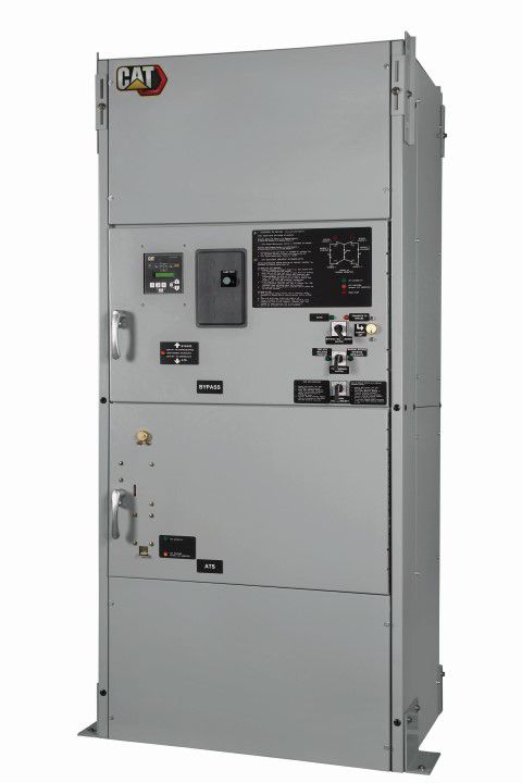
Image disclaimer: For identification and illustration only. It may show a product by another manufacturer and may not depict the exact item described; it is not a statement of any product’s quality, approval or performance. Third-party image and trademark rights belong to their owners. See full notice.
What Is It?
A CCR Bypass/Isolation Contactor is a dual‑purpose switching device used in AGL power distribution systems to provide both a bypass path around a CCR and a visible isolation point for maintenance. It typically comprises a set of mechanically and electrically interlocked contactors that can connect the series circuit directly to an alternate power source (such as a second CCR or a spare regulator) or completely isolate the CCR from the circuit, allowing safe servicing.
The bypass function is critical for maintaining airfield lighting continuity during CCR maintenance or failure. When a CCR needs to be taken out of service, the bypass contactor closes, routing the series circuit to the standby or backup CCR, while the isolation contactor opens to disconnect the faulty CCR. The isolation contactor also provides a visible break (when open) to ensure the circuit is de‑energised for safe maintenance work. This assembly is often integrated into the CCR cabinet or installed as a separate panel adjacent to the CCR bank.
Purpose & Function
This assembly exists to solve a conflict that would otherwise be unavoidable: a CCR that needs maintenance must be safely de-energised for the technician's protection, but the series circuit it feeds may need to stay lit for continued airfield operations. By pairing a bypass path to a standby regulator with a true isolating break on the faulty unit, the device lets both needs be met at once — the circuit keeps running on the alternate CCR while the original is genuinely disconnected, not just switched off at the control level. The isolation contactor's visible break specifically exists for technician safety, giving unambiguous physical confirmation that the CCR is de-energised, since a technician working on a device believed to be off but still electrically connected faces a serious risk that a control-level shutoff alone cannot fully rule out.
Where Is It Used?
CCR Bypass/Isolation Contactors are installed in airfield electrical rooms, equipment shelters, and AGL power centres where redundancy and maintenance flexibility are required. They are used in:
- Redundant CCR Configurations: Where a standby CCR is available to take over the load if the primary CCR fails or requires maintenance.
- Hot‑Swap Maintenance: Allowing a CCR to be replaced or serviced without interrupting the lighting circuit (provided a standby CCR is available).
- Precision Approach Runways (CAT I, II, III): Where high availability is mandated, and bypass capability is essential to minimise downtime.
- Critical Lighting Circuits: Runway edge, centreline, threshold, and approach lighting systems that must remain operational at all times.
- Integration with ALCMS: Enabling remote bypass and isolation control, with status feedback to the central control system.
- Testing and Commissioning: Allowing new CCRs to be tested while the existing regulator remains in service, using the bypass to switch between them.
Installation & Location
The assembly is installed in the equipment shelter as part of the CCR bank, either integrated into the CCR's own cabinet or mounted as a separate panel immediately adjacent to it, with the bypass and isolation contactors wired between the primary CCR, the standby CCR, and the outgoing series circuit. Positioning keeps the visible isolation break within clear sight of anyone working on the de-energised CCR, since the whole purpose of that break is to give unambiguous physical confirmation that the unit is disconnected before maintenance begins. Control wiring to the ALCMS or a local control panel is run alongside other CCR control cabling, allowing remote bypass switching, with the contactor's status feedback clearly labelled to the specific CCR pairing it manages in an equipment room that may house several redundant regulator sets. Because switching a fault onto a standby CCR needs to happen quickly and correctly, the interlocking between bypass and isolation contactors is verified during commissioning by testing an actual changeover, rather than assumed correct from the wiring diagram alone.
How Does It Work?
The bypass/isolation contactor assembly consists of three main contactor groups:
- Isolation Contactor (Normal Path): Connects the CCR's output to the series circuit. When closed, the CCR feeds the circuit. When open, the CCR is isolated from the circuit.
- Bypass Contactor: Connects an alternate power source (e.g., a standby CCR or a direct mains feed, though the latter is rare in AGL) to the same series circuit. When closed, the circuit is powered by the alternate source.
- Interlocking: Mechanical and electrical interlocks ensure that the isolation and bypass contactors are never closed simultaneously, preventing two CCRs from being paralleled (which would cause circulating currents and overloads).
The normal operating state has the isolation contactor closed and the bypass contactor open. When a transfer is required (e.g., for maintenance), the control system (or manual operator) first closes the bypass contactor to connect the standby CCR, then opens the isolation contactor to disconnect the primary CCR. This "make‑before‑break" sequence ensures no interruption to the lighting circuit. Conversely, when returning to normal operation, the isolation contactor is closed first, then the bypass contactor is opened. The assembly also includes auxiliary contacts for status indication (position feedback) to the ALCMS.
Make-before-break sequencing keeps the circuit powered through the transfer
Normal State
Isolation contactor closed, bypass contactor open — primary CCR feeds the circuit
1. Bypass contactor closes — standby CCR connects
2. Isolation contactor opens — primary CCR disconnects
1. Isolation contactor closes — primary CCR reconnects
2. Bypass contactor opens — standby CCR disconnects
Interlock Enforced Throughout
Both contactors are never closed together — no two CCRs are ever paralleled on the circuit
System Architecture & Control Logic
This assembly sits above the loop-level control described for individual fixtures — it decides which CCR feeds the circuit, not what current the circuit runs at. A transfer can originate two ways: a technician initiating a manual changeover for maintenance, or an automatic transfer triggered when the CCR regulator monitor (L-827) reports a regulator failure that the ALCMS has been configured to act on without waiting for manual intervention. Either way, the make-before-break sequencing and mechanical interlocking are what make the swap safe to leave to automation — the ALCMS never has to time the transfer itself, only issue the "transfer to standby" command and read back the resulting contactor positions from the auxiliary contacts. Because the standby CCR is a physically separate regulator, this level of redundancy protects against a CCR failure that would otherwise take the entire circuit dark, which is a different failure class from the individual fixture or transformer faults that ordinary loop-voltage monitoring is designed to catch.
Physical Construction
The bypass and isolation contactors are built as a matched pair, each with silver-alloy or silver-tungsten contacts sized to interrupt the CCR's rated series-circuit current and withstand the open-circuit voltage without excessive arcing, mounted on a common frame or DIN rail within a shared enclosure so their mechanical interlock can be built directly into the frame geometry. The mechanical interlock is a rigid linkage or interposed lever between the two contactor bodies that makes it physically impossible for both to be closed at once, backed by an electrical interlock using each contactor's auxiliary contacts wired into the other's coil circuit as a second, independent line of defence. Indoor installations use an IP20 open-frame or ventilated panel enclosure sized for the airflow the contactors need under frequent switching, while outdoor or unconditioned equipment shelters use a weatherproof IP54 enclosure with a viewing window so the visible isolation gap can be confirmed without opening the cabinet. Control wiring terminates at a separate, clearly labelled terminal block from the high-current power connections, and auxiliary contact wiring for remote status feedback is routed through its own gland or conduit entry to keep low-voltage control signals segregated from the switched series-circuit conductors.
Technical Parameters
| Parameter | Typical Value |
|---|---|
| Rated Current (Series Circuit) | 6.6A to 20A (depending on CCR rating) |
| Rated Voltage (Series Circuit) | Up to 5 kV (open circuit voltage of CCR) |
| Coil Voltage | 230V AC or 24V DC (standard) |
| Contact Material | Silver alloy or silver‑tungsten for arcing resistance |
| Mechanical Life | > 1 million operations |
| Electrical Life (at rated load) | > 100,000 operations |
| Auxiliary Contacts | 2–4 NO/NC contacts per contactor |
| Interlock Type | Mechanical and electrical (anti‑simultaneous) |
| Enclosure | Indoor (IP20) or outdoor (IP54) with weatherproofing |
| Standards | IEC 60947, UL 508 |
Electrical Requirements
| Requirement | Typical Value |
|---|---|
| Series Circuit Wiring | Rated to 6.6A-20A loop current, up to 5kV open-circuit voltage |
| Control Coil Supply | 230V AC or 24V DC, fed from the CCR cabinet control circuit |
| Interlock Wiring | Hard-wired mechanical/electrical anti-simultaneous interlock between bypass and isolation contactors |
| Auxiliary Contact Wiring | Dry contacts to ALCMS/annunciator for position and status feedback |
| Isolation Verification | Visible break confirmed before maintenance access |
| Earthing/Grounding | Contactor frame and cabinet bonded to equipment-room earth bus |
| Power Source | CCR bank control circuit; series-circuit contacts fed from the CCR output |
Applicable Standards
IEC 60947
Low‑voltage switchgear and controlgear — general requirements for contactors and motor starters
UL 508
Industrial Control Equipment — covers contactors used in industrial applications, including AGL
IEC 61822
Electrical installation and performance requirements for AGL constant current regulators — references bypass and isolation arrangements
BS EN 60947-4-1
Contactors and motor‑starters — electromechanical contactors and starters
Installation Requirements
CCR Bank Positioning
SiteInstall in the equipment shelter as part of the CCR bank, either integrated into the CCR's own cabinet or mounted as a separate panel immediately adjacent to it.
Contactor Wiring Between CCR Sets
ElectricalWire the bypass and isolation contactors between the primary CCR, the standby CCR, and the outgoing series circuit.
Visible Isolation Break Positioning
MechanicalPosition the visible isolation break within clear sight of anyone working on the de-energised CCR, so it gives unambiguous physical confirmation the unit is disconnected.
Control Wiring to ALCMS
ElectricalRun control wiring to the ALCMS or local control panel alongside other CCR control cabling to allow remote bypass switching.
Status Feedback Labelling
DocumentationLabel the contactor's status feedback clearly to the specific CCR pairing it manages, particularly in equipment rooms housing several redundant regulator sets.
Mechanical/Electrical Interlock Wiring
ElectricalWire the anti-simultaneous mechanical and electrical interlock between bypass and isolation contactors per the manufacturer's logic.
Changeover Test Verification
DocumentationVerify the interlocking between bypass and isolation contactors by testing an actual changeover during commissioning, rather than assuming correctness from the wiring diagram alone.
Pre-Energisation Sign-off
DocumentationRecord contactor wiring, interlock test results, and status labelling as-built before the CCR bank is closed up.
Testing & Commissioning
Interlock Function Test
Pre-EnergisationConfirm mechanical and electrical interlocks prevent simultaneous closure of conflicting contactors before the assembly is energised.
Manual Isolation Test
InstallationOperate the isolation function and confirm it provides a visible, positive break, isolating the CCR completely from the circuit.
Coil Voltage & Auxiliary Contact Check
Pre-EnergisationConfirm coils operate reliably at rated control voltage and that auxiliary contacts correctly report contactor position.
Contact Resistance Check
InstallationMeasure resistance across the main contacts before the circuit is energised.
Automatic Transfer Test
Final AcceptanceSimulate a CCR fault and confirm automatic transfer to the bypass or alternate source operates correctly and within the specified time.
Documentation & As-Built Sign-off
Final AcceptanceRecord interlock, contact resistance, and transfer test results in the commissioning dossier.
Inspection & Maintenance
Contact Wear Inspection
AnnualCheck silver or silver-tungsten contacts for pitting or arcing damage, since this contactor switches at the CCR's open-circuit voltage during bypass transfer.
Interlock Function Test
Semi-annualConfirm the mechanical and electrical anti-simultaneous interlock still prevents both the CCR and bypass path from being energised together.
Automatic Transfer Test
Semi-annualSimulate a regulator failure to confirm the contactor correctly transfers the circuit to standby and reports the transfer to the ALCMS.
Coil Voltage Check
AnnualVerify the coil operates correctly at rated 230V AC or 24V DC and pulls in cleanly without chattering.
Auxiliary Contact Verification
Semi-annualConfirm auxiliary NO/NC contacts correctly report contactor position, since this is how the ALCMS knows which path is active.
Terminal & Connection Tightness Check
AnnualRe-torque incoming and outgoing terminal connections to spec, since loose terminations under series-circuit current can overheat.
Enclosure & Seal Inspection
AnnualFor outdoor-rated units, inspect enclosure gaskets and glands to confirm the rated IP54 protection is intact.
Mechanical Life Tracking
AnnualTrack operation count against the rated 1 million mechanical / 100,000 electrical life so the contactor is scheduled for replacement before wear-driven failure.
Common Field Issues
Interlock Failure
Mechanical or electrical interlocks may fail, allowing both the isolation and bypass contactors to close simultaneously. This can cause paralleling of CCRs, leading to severe overcurrent and potential damage. Regular testing of interlocks is critical.
Contact Wear on Bypass Contactor
The bypass contactor may be operated infrequently but must be capable of carrying full load. Over time, contact surfaces can oxidise or pit, increasing resistance and causing overheating. Periodic inspection and exercising are recommended.
Coil Burnout
Prolonged energisation or voltage spikes can cause coil failure. Surge suppression across coils and proper control logic (e.g., not holding coils for extended periods) can extend life.
Position Indication Errors
Auxiliary contacts may fail, leading to incorrect status reporting to the ALCMS. This can prevent automated transfer sequences from executing correctly. Regular verification of auxiliary contacts is essential.
Arc Chute Degradation
The arc chutes on the bypass contactor (and isolation contactor) can degrade over time, especially if the contactor interrupts load current. Visual inspection and timely replacement of arc chutes are necessary to maintain safe interruption capability.
Troubleshooting Guide
Both Contactors Show Closed Simultaneously
Bypass Contactor Runs Hot or Trips on Transfer
Contactor Fails to Energise / Coil Dead
ALCMS Shows Incorrect Contactor Status
Visible Arcing or Damage at Contact Opening
Failure Modes & Root Causes
Interlock Mechanism Failure
Bypass Contact Oxidation / Pitting
Coil Burnout
Auxiliary Contact Failure
Arc Chute Degradation
Control Circuit / Sequencing Fault
Safety & Operational Notes
Isolate Both Sources Before Work
Electrical SafetyDe-energise and lock out both the primary CCR and the bypass/alternate source before working inside the enclosure, since the unit is specifically designed to connect two live sources and either can carry the series circuit voltage.
Verify Interlock Before Manual Operation
Electrical SafetyConfirm the mechanical and electrical interlock is intact before manually cycling either contactor; a defeated or worn interlock can allow both paths to close together and parallel the CCR output with the bypass, risking fault current or regulator damage.
Confirm Position Before Re-Energising
OperationalPhysically verify contactor position matches the intended state (bypass or normal) before restoring power, rather than relying solely on ALCMS auxiliary contact status, since a stuck or welded contact can misreport its own position.
Airside Work Coordination
OperationalAny transfer to bypass or maintenance state that takes a lighting circuit off its normal regulation requires ATC/airside coordination and a NOTAM where the affected fixtures will be out of tolerance or dark.
Insulation Test Before Re-Energisation
Electrical SafetyAfter any internal work, megger test the affected circuit paths before restoring power, since a residual fault at re-energisation can damage the regulator or trip healthy circuits sharing the same board.
PPE & Grounding
Personnel SafetyUse insulated tools and appropriate PPE when working near series-circuit connections, and confirm the enclosure is bonded/grounded per the electrical design before reconnecting either path.
FOD & Enclosure Integrity
OperationalAccount for all tools and fasteners before closing the enclosure, and confirm the door/lid seal is properly reinstated to keep moisture and debris out of the contactor assembly.
Restore to Compliant State
ComplianceDo not leave the unit in bypass, with the interlock defeated, or in an unverified position after maintenance; confirm normal-path operation and full interlock function before closing out the work and cancelling any associated NOTAM.
Engineering & Expert Notes
Interlock Integrity Is the Whole Point — Test It, Don't Assume It
SafetyThe mechanical/electrical interlock preventing simultaneous closure of bypass and isolation contactors is the single component this device exists for; verify it functionally at every maintenance visit rather than relying on the assembly's original factory test, since a worn or defeated interlock can leave both paths closed under fault conditions with no visible warning.
Confirm the Visible Break Is Actually Visible
VerificationAn isolation contactor's visible-break feature only provides genuine safety assurance if the open contacts can actually be observed or independently verified from outside the enclosure; a viewing window obscured by dust or a contactor mounted where the gap can't be seen defeats the purpose even though the device itself is functioning correctly.
Bypass Switching Under Load Stresses Contacts Differently Than Normal Operation
MaintenanceContactors that only operate during a CCR swap-over see infrequent but high-stress switching events rather than routine cycling; contact wear from these events can be more severe per-operation than a contactor cycling normally, so inspect contact condition based on switching severity, not just operation count.
A Standby Path That's Never Exercised Is Unproven
ReliabilityAn assembly that hasn't performed an actual bypass operation in months or years provides no real assurance it will work correctly during a genuine CCR failure; schedule a planned exercise of the full bypass sequence rather than discovering a stuck contactor for the first time during an actual emergency changeover.
Verify Control Logic Sequencing, Not Just the Contactors Themselves
ControlsThe contactors can be mechanically and electrically sound while the ALCMS or PLC sequencing that commands them has a timing fault, causing a brief make-before-break or break-before-make condition outside the intended sequence; periodically verify the actual switching sequence and timing, not just that each contactor operates when commanded individually.
Log Every Bypass Event With Its Reason
DocumentationA bypass/isolation assembly that switches unexpectedly or more frequently than planned is often an early symptom of an intermittent CCR fault rather than a problem with the contactor assembly itself; keeping a log of every bypass event and its cause makes that pattern visible instead of each event being treated as an isolated occurrence.
Frequently Asked Questions
Short answers about the CCR Bypass/Isolation Contactor: what it is, how it works, typical specifications, standards, maintenance and common faults.
Q1What is a CCR Bypass/Isolation Contactor?
A CCR Bypass/Isolation Contactor is a dual‑purpose switching device used in AGL power distribution systems to provide both a bypass path around a CCR and a visible isolation point for maintenance. It typically comprises a set of mechanically and electrically interlocked contactors that can connect the series circuit directly to an alternate power source (such as a second CCR or a spare regulator) or completely isolate the CCR from the circuit, allowing safe servicing.
Q2What is the purpose of a CCR Bypass/Isolation Contactor?
This assembly exists to solve a conflict that would otherwise be unavoidable: a CCR that needs maintenance must be safely de-energised for the technician's protection, but the series circuit it feeds may need to stay lit for continued airfield operations.
Q3Where is a CCR Bypass/Isolation Contactor used and installed?
CCR Bypass/Isolation Contactors are installed in airfield electrical rooms, equipment shelters, and AGL power centres where redundancy and maintenance flexibility are required. They are used in: Redundant CCR Configurations: Where a standby CCR is available to take over the load if the primary CCR fails or requires maintenance. Hot‑Swap Maintenance: Allowing a CCR to be replaced or serviced without interrupting the lighting circuit (provided a standby CCR is available).
Q4How does a CCR Bypass/Isolation Contactor work?
The bypass/isolation contactor assembly consists of three main contactor groups: Isolation Contactor (Normal Path): Connects the CCR's output to the series circuit. When closed, the CCR feeds the circuit. When open, the CCR is isolated from the circuit. Bypass Contactor: Connects an alternate power source (e.g., a standby CCR or a direct mains feed, though the latter is rare in AGL) to the same series circuit. When closed, the circuit is powered by the alternate source.
Q5What are the typical technical parameters of a CCR Bypass/Isolation Contactor?
Typical values are — Rated Current (Series Circuit): 6.6A to 20A (depending on CCR rating); Rated Voltage (Series Circuit): Up to 5 kV (open circuit voltage of CCR); Coil Voltage: 230V AC or 24V DC (standard); Contact Material: Silver alloy or silver‑tungsten for arcing resistance; Mechanical Life: > 1 million operations; Electrical Life (at rated load): > 100,000 operations; Auxiliary Contacts: 2–4 NO/NC contacts per contactor; Interlock Type: Mechanical and electrical (anti‑simultaneous); Enclosure: Indoor (IP20) or outdoor (IP54) with weatherproofing; Standards: IEC 60947, UL 508.
Q6What are the electrical requirements for a CCR Bypass/Isolation Contactor?
Typical requirements are — Series Circuit Wiring: Rated to 6.6A-20A loop current, up to 5kV open-circuit voltage; Control Coil Supply: 230V AC or 24V DC, fed from the CCR cabinet control circuit; Interlock Wiring: Hard-wired mechanical/electrical anti-simultaneous interlock between bypass and isolation contactors; Auxiliary Contact Wiring: Dry contacts to ALCMS/annunciator for position and status feedback; Isolation Verification: Visible break confirmed before maintenance access; Earthing/Grounding: Contactor frame and cabinet bonded to equipment-room earth bus; Power Source: CCR bank control circuit; series-circuit contacts fed from the CCR output.
Q7Which standards apply to a CCR Bypass/Isolation Contactor?
The main references are IEC 60947 — Low‑voltage switchgear and controlgear — general requirements for contactors and motor starters; UL 508 — Industrial Control Equipment — covers contactors used in industrial applications, including AGL; IEC 61822 — Electrical installation and performance requirements for AGL constant current regulators — references bypass and isolation arrangements; BS EN 60947-4-1 — Contactors and motor‑starters — electromechanical contactors and starters. Always verify the current edition and your aerodrome's approved requirements.
Q8How often should a CCR Bypass/Isolation Contactor be inspected and maintained?
Typical maintenance tasks and intervals are: Contact Wear Inspection (annual); Interlock Function Test (semi-annual); Automatic Transfer Test (semi-annual); Coil Voltage Check (annual); Auxiliary Contact Verification (semi-annual); Terminal & Connection Tightness Check (annual); Enclosure & Seal Inspection (annual); Mechanical Life Tracking (annual). Your airport's approved maintenance programme takes precedence.
Q9How do I troubleshoot common CCR Bypass/Isolation Contactor faults?
Common symptoms covered are: Both Contactors Show Closed Simultaneously; Bypass Contactor Runs Hot or Trips on Transfer; Contactor Fails to Energise / Coil Dead; ALCMS Shows Incorrect Contactor Status; Visible Arcing or Damage at Contact Opening. For example, for "Both Contactors Show Closed Simultaneously": Likely Cause: Mechanical or electrical interlock failure has allowed the isolation and bypass contactors to close together, risking CCR paralleling. Diagnostic Steps: Immediately de-energise and manually verify contactor positions; test the mechanical and electrical interlocks through a full operating cycle. Corrective Action: Repair or replace the failed interlock mechanism, and re-verify correct interlocking before returning the assembly to automatic operation.
Related Components
Go Beyond the Component. Understand the Complete AGL System.
You have explored the component. Now understand how it works within the complete Airfield Ground Lighting system.
Learn AGL from fundamentals to design, installation, testing, photometry, commissioning, maintenance and troubleshooting through structured technical training at Precision AGL Academy.
Build practical knowledge. Understand the circuit. Read the standards. Troubleshoot with confidence.
Your next step in AGL starts here.
Need expert guidance on CCR bypass/isolation contactor design, integration, or maintenance?
Precision AGL Academy provides advice on redundancy schemes, contactor coordination, and ALCMS integration for seamless CCR bypass and isolation.
Follow the Academy
Important Notice, Disclaimer & Limitation of Liability
Please read before relying on any content on this page.
- Purpose and intended users. This page on CCR Bypass/Isolation Contactor is an independent educational and informational reference for competent, suitably trained and authorised airfield ground lighting (AGL) and aerodrome electrical personnel. It is not professional engineering, legal or regulatory advice, and using it does not create any professional or client relationship.
- Safety. Work on series circuits, constant current regulators (CCRs), isolating transformers, cables, connectors and lighting equipment can be fatal. Always apply the aerodrome’s permit-to-work and isolation/LOTO procedures, prove dead, use correctly rated instruments and PPE, and follow the manufacturer’s instructions. Nothing here authorises work on live equipment or the bypassing of any safety device or interlock.
- Aviation operations. Nothing here authorises installation, modification, energisation, adjustment, return to service, a change of operating category (CAT I/II/III), a NOTAM or any aerodrome certification or approval decision. These rest with the aerodrome operator, the air navigation service provider and the competent regulator.
- Specifications, ratings and typical values. Descriptions, parameters, ratings, dimensions, photometric values, wattages, service lives, maintenance tasks and intervals, failure modes, certifications (for example CE, FCC, UL or IEC marks) and part or type designations are general, typical and indicative. They may not match any particular product, make, model or version, and they are not a datasheet, design, specification, selection, sizing, procurement or acceptance criterion. The manufacturer’s current documents, the approved design and the project specification prevail.
- Standards and regulations. References to ICAO, FAA, IEC, IEEE, ISO, BIS, DGCA and other standards are paraphrased summaries for orientation only. They may be incomplete or out of date, and standards are revised from time to time. Consult the current official editions. Following this content does not guarantee compliance with any law, standard or regulatory approval, and the regulator’s requirements always prevail.
- No warranty. Content is provided “as is” and “as available”, without warranty of any kind, express or implied, including accuracy, completeness, currency or fitness for a particular purpose. Real installations differ in design, equipment make and model, age and condition.
- Limitation of liability. To the fullest extent permitted by applicable law, Precision AGL Academy, Precision AGL Solutions and their owners, authors and contributors are not liable for any injury, death, loss, damage, downtime, penalty or regulatory consequence, whether direct or indirect, arising from the use of, reliance on, or inability to use this content. Nothing in this notice excludes or limits any liability that cannot lawfully be excluded or limited.
- Independence, brands and no endorsement. This is an independent publication. It is not affiliated with, sponsored by or endorsed by ICAO, the FAA, the IEC, DGCA, AAI, any airport, regulator, supplier or equipment manufacturer. Third-party names, product designations, standard designations and trademarks (including Megger®, Siemens, Eaton, Crouse-Hinds, ADB SAFEGATE, Fluke, ABB and Honeywell) belong to their respective owners and are used only for identification and description. Mention of a brand, product or supplier is not a recommendation, and we do not sell, supply or quote for any component described.
- Images and third-party content. Images and illustrations are shown to help identify the type of component. They may show products of various manufacturers, may not depict the exact item described, and are not a statement about any product’s quality, approval or performance. Copyright and trademarks in third-party images, logos and photographs belong to their respective owners and are not claimed as ours. If you are a rights holder and want an image removed, replaced or credited, email precisionaglsolutions@gmail.com with the page address and we will act promptly.
- Training and services. Mentions of training, courses, consultation, advice, selection, installation, calibration or other support, including the “Learn…Certify” pathway, describe learning stages and are not an offer, quotation, tender or promise of any result. Contacting us or our replying creates no engagement or duty of care; an engagement exists only under a written agreement. We are not a regulator or certification body, and completing any course or reading this content is not a certification, accreditation or authorisation to work on any aerodrome.
- Copyright, privacy and corrections. © 2026 Precision AGL Academy. All rights reserved. Text, structure, compilations and diagrams may be viewed for personal reference and internal training only; any other copying, republication or commercial use needs our written permission. If you email, telephone or message us, we use your details only to respond and handle your matter, in line with applicable Indian law including the Digital Personal Data Protection Act, 2023; please do not send confidential or security-sensitive information. To display this page your browser requests fonts, icons and images from third-party servers, which receive your IP address and browser details under their own policies. Content is reviewed periodically with no obligation to update. To report an error, safety concern or rights issue, write to precisionaglsolutions@gmail.com.