Circuit Breaker
An automatically operated electrical switch designed to protect an AGL circuit from damage caused by overload or short circuit. Unlike an isolation switch, a circuit breaker detects a fault condition and interrupts current flow, preventing equipment damage and ensuring the safety of personnel and infrastructure. Circuit breakers are essential components in Airfield Ground Lighting power distribution and control systems.
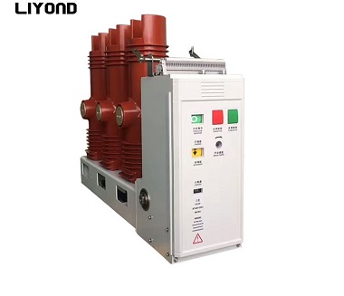
Image disclaimer: For identification and illustration only. It may show a product by another manufacturer and may not depict the exact item described; it is not a statement of any product’s quality, approval or performance. Third-party image and trademark rights belong to their owners. See full notice.
What Is It?
A Circuit Breaker is an automatically operated electrical switching device that protects an electrical circuit from damage caused by excess current due to overload, short circuit, or ground fault. In Airfield Ground Lighting (AGL) systems, circuit breakers are used in both primary (series) and secondary (control and distribution) circuits to protect the CCRs, transformers, cables, and lighting fixtures. Unlike fuses, which must be replaced after a single fault, circuit breakers can be reset (either manually or automatically) after the fault is cleared, making them reusable and more convenient for maintenance.
AGL circuit breakers are typically designed for:
- Series Lighting Circuits: Used at the CCR output to protect against short circuits in the series loop.
- Control and Monitoring Circuits: Protecting the ALCMS, PLCs, and communication equipment.
- Distribution Panels: Protecting feeder cables to various airfield sectors.
Purpose & Function
The circuit breaker's purpose, in general, is the same one that its MCB and MCCB variants specialise in at different current ranges: to sense an overload or short circuit and interrupt the faulted circuit automatically before it can damage cables, transformers, CCRs, or lighting fixtures, while allowing that circuit to be safely restored once the fault is cleared. In an AGL series circuit specifically, the breaker at the CCR output exists to protect the entire loop of fixtures and isolating transformers from a short circuit anywhere along its length, converting what could otherwise be a sustained overcurrent event into a brief, contained interruption. Its reusability compared to a fuse is itself part of its purpose — it lets maintenance crews restore power quickly after clearing a fault without needing replacement parts, minimising how long a runway or taxiway section is left without lighting.
Where Is It Used?
Circuit breakers are used throughout the AGL power and control infrastructure:
- In CCR Panels: Protecting the output of each Constant Current Regulator from short circuits in the series loop.
- In Distribution Boards: Providing overcurrent protection for sub‑circuits feeding different airfield sectors (runways, taxiways, aprons).
- In ALCMS Racks: Protecting control and monitoring equipment (PLCs, servers, communication modules).
- In Lighting Control Panels: Protecting individual lighting circuits and stop bar circuits.
- In Substations: As the main incoming protection for the AGL power supply.
Installation & Location
Circuit breakers are DIN-rail or panel-mounted inside CCR cabinets, distribution boards, ALCMS racks, and substation switchgear, positioned so the protected cable enters and leaves the enclosure with a short, well-supported run to the breaker's terminals. Mounting orientation and spacing follow the manufacturer's derating tables, since breakers mounted close together or in a sealed enclosure need extra clearance or ventilation to avoid nuisance tripping from internal heat build-up. Each breaker is labelled to identify the circuit it protects, and its position within the panel is chosen to keep discrimination and access logical — main incomers at the top or one side, feeder breakers grouped by the section of the airfield they serve — so a fault can be traced and isolated quickly.
How Does It Work?
A circuit breaker operates using a combination of thermal and magnetic (or electronic) trip mechanisms:
- Overload Protection (Thermal): A bimetallic strip heats up and bends when current exceeds the rated value for a sustained period. The bending triggers the trip mechanism, opening the contacts after a time delay that is inversely proportional to the overcurrent (trip time decreases as current increases). This protects against moderate, prolonged overcurrents.
- Short‑Circuit Protection (Magnetic): A magnetic coil generates a force proportional to the current. Under high fault currents (short circuits), the magnetic force is sufficient to instantly open the contacts, providing near‑instantaneous interruption.
- Electronic Trip Units: Modern circuit breakers (especially MCCBs) use microprocessor‑based trip units that provide programmable protection curves, including long‑time, short‑time, instantaneous, and ground‑fault protection.
- Arc Extinction: When the contacts open, an arc is formed. Circuit breakers use arc chutes, de‑ionizing plates, or vacuum/SF6 interrupter chambers to extinguish the arc quickly, ensuring safe interruption.
- Reset: After a fault is cleared, the circuit breaker can be reset manually (by pushing the handle to the ON position) or automatically (in some remote‑controlled breakers).
System Architecture & Control Logic
Circuit breakers in an AGL network are arranged in a protection hierarchy rather than operating in isolation: an incomer or MCCB at the distribution board sits above a series of downstream MCBs or MCCBs feeding individual CCRs and circuits, and the trip curves are graded (discrimination) so that the breaker closest to a fault opens before any breaker upstream of it, limiting an outage to the smallest possible section of the network. Where a breaker includes an auxiliary or alarm contact, its open/closed and tripped status can be wired back to a local annunciator panel or, on larger sites, polled by the ALCMS or a building management system, giving remote visibility of which circuit has tripped without a technician having to inspect each panel physically. Breakers without such contacts remain purely local protection devices — their trip is visible only at the breaker handle, and diagnosing which breaker opened after a wider outage is done by physical inspection rather than remote reporting.
Three Protection Paths, One Outcome
Physical Construction
The breaker's current-carrying path runs through a set of silver-alloy contacts operated by a spring-loaded toggle mechanism, housed within an arc chamber of ceramic or high-temperature thermoset plastic designed to split and extinguish the arc generated when the contacts open under fault current. A bimetallic strip provides thermal overload protection while a solenoid or electromagnetic element delivers instantaneous magnetic tripping on short-circuit currents, both acting on a common trip bar to open the contacts regardless of which mechanism triggers. The MCCB's moulded case, or the MCB's compact insulated housing, is built from flame-retardant, high-dielectric-strength thermoset or thermoplastic material to contain internal arcing and prevent case rupture under maximum fault conditions. External terminals are shrouded to prevent accidental contact, and the assembly snaps onto a standard DIN rail or bolts to a panel via base-mounting holes, with a clear, positive on/off/tripped indicator visible on the operating handle.
Technical Parameters
| Parameter | Typical Value |
|---|---|
| Type | MCB (Miniature Circuit Breaker) or MCCB (Moulded Case Circuit Breaker) |
| Rated Current (In) | 6A, 10A, 16A, 20A, 32A, 40A, 63A, 100A, etc. |
| Rated Voltage | 230V / 400V AC (up to 1000V AC) |
| Breaking Capacity (Icu) | 10kA, 18kA, 25kA, 36kA, 50kA (depending on type) |
| Trip Characteristics | B‑curve (3‑5 In), C‑curve (5‑10 In), D‑curve (10‑20 In) |
| Poles | 1‑pole, 2‑pole, 3‑pole, 4‑pole |
| Mechanical Endurance | > 20,000 operations |
| Electrical Endurance | > 10,000 operations at rated current |
| Enclosure Rating | IP20 (indoor panels), IP65 (outdoor enclosures) |
| Mounting | DIN rail, panel‑mount, or plug‑in |
| Operating Temperature | ‑25°C to +70°C |
| Standards Compliance | IEC 60898, IEC 60947‑2, UL 489, NFPA 70 (NEC) |
Electrical Requirements
| Requirement | Typical Value |
|---|---|
| Circuit Position | Installed in primary (series) or secondary (control/distribution) AGL circuits ahead of CCRs, transformers, and fixtures |
| Upstream Cabling | Sized to rated current (In) and derated per enclosure/ambient conditions |
| Downstream Cabling | Sized to the protected circuit's load and fault-current withstand rating |
| Fault Level Coordination | Breaking capacity (Icu) selected to exceed the prospective fault current at the point of installation |
| Earthing/Grounding | Enclosure and DIN rail/mounting frame bonded to the panel earth bar |
| Discrimination | Trip curve (B/C/D) coordinated with upstream/downstream devices to ensure selective tripping |
Applicable Standards
IEC 60947‑2
Low‑voltage switchgear – Circuit breakers
IEC 60898
Circuit‑breakers for overcurrent protection for household and similar installations (MCBs)
UL 489
Molded‑Case Circuit Breakers (MCCBs) and Circuit Breaker Enclosures
NFPA 70 (NEC)
National Electrical Code — governs circuit breakers and other commercial electrical items not covered by a dedicated FAA specification
Installation Requirements
Panel/DIN-Rail Mounting
MechanicalMount the breaker on DIN-rail or panel within the CCR cabinet, distribution board, ALCMS rack, or switchgear it belongs to.
Spacing & Derating Clearance
MechanicalFollow the manufacturer's derating tables for mounting orientation and spacing, since breakers grouped closely or in a sealed enclosure need extra clearance or ventilation to avoid nuisance tripping.
Cable Termination
ElectricalTerminate the protected cable at the breaker's terminals with a short, well-supported run entering and leaving the enclosure.
Circuit Labelling
DocumentationLabel each breaker to identify the circuit it protects, positioned in the panel to keep discrimination and access logical.
Panel Layout & Grouping
DocumentationPosition main incomers at the top or one side and group feeder breakers by the section of the airfield they serve, so a fault can be traced and isolated quickly.
Pre-Energisation Sign-off
DocumentationRecord breaker position, rating, and circuit labelling as-built before the panel is accepted for commissioning.
Testing & Commissioning
Insulation Resistance (Megger) Test
Pre-EnergisationMegger-test the breaker and downstream wiring before energisation, confirming insulation resistance clears the acceptable minimum ahead of loading.
Contact Resistance & Continuity Test
Pre-EnergisationMeasure contact resistance across the closed breaker to rule out high-resistance contacts that could cause nuisance heating under load.
Primary/Secondary Injection Trip Test
CommissioningInject test current through the breaker to verify the thermal and magnetic trip elements operate within tolerance of the rated trip curve (B/C/D).
Mechanical Operation Check
CommissioningCycle the breaker through on/off/trip several times to confirm a positive, tactile toggle action and correct handle indication at each state.
Terminal Torque Verification
Pre-EnergisationTorque all line and load terminations to the manufacturer's specified value and re-check after initial thermal cycling.
Rated Current & Voltage Verification
CommissioningConfirm the installed breaker's rated current, voltage, and breaking capacity match the design specification for its position in the circuit.
Documentation & As-Built Sign-off
Final AcceptanceRecord insulation, contact resistance, and trip test results alongside the breaker's rating and position in the commissioning dossier.
Inspection & Maintenance
Trip Curve / Setting Verification
AnnualConfirm the selected trip curve (C-curve or D-curve) and adjustable settings still match the load profile to avoid nuisance tripping.
Contact Inspection & Operation Count Review
AnnualInspect contacts for erosion and review the fault-operation count against the manufacturer's replacement interval.
Thermal Derating Review
AnnualReassess current-carrying capacity against actual ambient enclosure temperatures and apply derating factors where needed.
Fault Current Coordination Check
AnnualVerify available fault current at the installation point remains within the breaker's rated breaking capacity (Icu).
Mechanical Operation Test
AnnualManually operate the breaker to confirm smooth mechanical action and correct trip-free operation.
Common Field Issues
Nuisance Tripping
Circuit breakers may trip due to temporary overloads (e.g., inrush current during CCR start‑up) or harmonic currents. Selecting the correct trip curve (C‑curve or D‑curve) and adjusting the setting (if adjustable) is essential to avoid nuisance tripping.
Contact Wear and Arcing
Repeated fault interruptions cause contact erosion and degradation of the arc‑chute. Regular inspection and replacement of breakers after a specified number of fault operations (or at scheduled intervals) is recommended.
Thermal Derating
Circuit breakers are rated at a specific ambient temperature (typically 30°C or 40°C). Higher ambient temperatures (common in outdoor enclosures) reduce the current‑carrying capacity. Derating factors must be applied or higher‑rated breakers selected.
Inadequate Breaking Capacity
If the short‑circuit current at the installation point exceeds the breaker's breaking capacity (Icu), the breaker may fail to interrupt the fault safely, leading to catastrophic failure. Always verify the available fault current and select an appropriate breaker.
Troubleshooting Guide
Breaker Trips Immediately on Reset
Nuisance Tripping Under Normal Load
Breaker Fails to Trip Under a Confirmed Fault
Overheating at Breaker Terminals
Breaker Will Not Reset / Mechanically Jammed
Failure Modes & Root Causes
Persistent Downstream Fault or Mechanism Lockout
Trip Curve Mismatch
Worn Contacts or Insufficient Breaking Capacity
Loose Terminal Connection
Mechanical Jamming or Contact Welding
Safety & Operational Notes
Upstream Isolation Before Removal
Electrical SafetyDe-energise and lock out the upstream supply before removing or replacing a circuit breaker, and verify zero energy at its terminals before disconnecting wiring, even though the breaker's own contacts are open.
Correct Rating on Replacement
ComplianceFit a replacement breaker with the same rated current and breaking capacity as the original, verified against the protected circuit's design load and prospective fault current; an undersized breaking capacity can fail to safely interrupt a fault.
Investigate Before Resetting a Tripped Breaker
Personnel SafetyInvestigate the cause of a trip before resetting a breaker; repeatedly forcing it closed against a persistent fault can damage the breaker and leave the circuit inadequately protected.
Test Before Re-Energisation
Electrical SafetyAfter any work downstream of a breaker, verify insulation resistance and correct load connection before closing it, since a residual fault at re-energisation can cause a nuisance trip or equipment damage.
PPE for Panel Work
Personnel SafetyUse insulated tools and appropriate PPE when working inside a distribution board or CCR panel, and be aware of adjacent live circuits on other breakers in the same enclosure.
FOD Control at the Panel
OperationalKeep tools, fasteners, and breaker blanks accounted for at all times when a panel is open, and secure or remove any loose material before closing it, particularly in panels serving critical control or lighting circuits.
Check for Thermal Damage on Replacement
Personnel SafetyInspect the busbar and adjacent breakers for discolouration or heat damage when replacing a breaker that tripped repeatedly or showed signs of overheating, since a hot connection can damage neighbouring equipment.
Restore to Compliant State
ComplianceDo not leave a panel with an incorrectly rated breaker, an unlabelled circuit, or a loose termination after maintenance; verify correct labelling and torque before closing out the work order.
Engineering & Expert Notes
Series-Circuit Breakers Need Fault-Current Coordination, Not Just a Rating
CoordinationA breaker protecting a CCR series loop needs its trip settings coordinated against the constant-current regulator's own fault response, not just sized to the loop's steady-state current; a mismatch can leave the CCR's internal protection racing the breaker on every fault, with inconsistent results.
Match Trip Curve to Inrush Behaviour on Control Circuits
SelectionNuisance tripping on control and distribution circuits is very often a trip-curve mismatch against inrush current from PLCs, transformers, or contactors, not an undersized breaker; check the curve type before resizing the breaker upward.
Intermittent Tripping With No Fault Found Warrants a Load Study
TroubleshootingA breaker that trips occasionally with nothing obviously wrong on inspection is often responding to a marginal cumulative load condition rather than a genuine fault; a short load-logging exercise usually resolves it faster than repeated fault-finding on the wiring.
Exercise Standby Breakers on a Schedule
MaintenanceBreakers protecting rarely-used or standby circuits can develop a stiff or sluggish mechanism from years without operation; build periodic manual operation into the maintenance plan so a mechanism that won't trip or close cleanly is caught before it's needed for real.
Panel Ambient Temperature Shifts the Effective Rating
DesignThermal-element trip characteristics are rated at a reference ambient; a tightly packed, hot-running panel can cause a breaker to trip below its nameplate current. Where panels run warm, derate selection accordingly rather than relying on the nameplate figure alone.
Record the Exact Replacement Spec, Not Just "Equivalent"
DocumentationWhen a failed breaker is replaced, record the curve type, breaking capacity, and settings actually fitted; a spare that's superficially equivalent on current rating alone can silently undermine the coordination the original design engineer calculated.
Frequently Asked Questions
Short answers about the Circuit Breaker: what it is, how it works, typical specifications, standards, maintenance and common faults.
Q1What is a Circuit Breaker?
A Circuit Breaker is an automatically operated electrical switching device that protects an electrical circuit from damage caused by excess current due to overload, short circuit, or ground fault. In Airfield Ground Lighting (AGL) systems, circuit breakers are used in both primary (series) and secondary (control and distribution) circuits to protect the CCRs, transformers, cables, and lighting fixtures.
Q2What is the purpose of a Circuit Breaker?
The circuit breaker's purpose, in general, is the same one that its MCB and MCCB variants specialise in at different current ranges: to sense an overload or short circuit and interrupt the faulted circuit automatically before it can damage cables, transformers, CCRs, or lighting fixtures, while allowing that circuit to be safely restored once the fault is cleared.
Q3Where is a Circuit Breaker used and installed?
Circuit breakers are used throughout the AGL power and control infrastructure: In CCR Panels: Protecting the output of each Constant Current Regulator from short circuits in the series loop. In Distribution Boards: Providing overcurrent protection for sub‑circuits feeding different airfield sectors (runways, taxiways, aprons). In ALCMS Racks: Protecting control and monitoring equipment (PLCs, servers, communication modules). In Lighting Control Panels: Protecting individual lighting circuits and stop bar circuits. In Substations: As the main incoming protection for the AGL power supply.
Q4How does a Circuit Breaker work?
A circuit breaker operates using a combination of thermal and magnetic (or electronic) trip mechanisms: Overload Protection (Thermal): A bimetallic strip heats up and bends when current exceeds the rated value for a sustained period. The bending triggers the trip mechanism, opening the contacts after a time delay that is inversely proportional to the overcurrent (trip time decreases as current increases). This protects against moderate, prolonged overcurrents. Short‑Circuit Protection (Magnetic): A magnetic coil generates a force proportional to the current.
Q5What are the typical technical parameters of a Circuit Breaker?
Typical values are — Type: MCB (Miniature Circuit Breaker) or MCCB (Moulded Case Circuit Breaker); Rated Current (In): 6A, 10A, 16A, 20A, 32A, 40A, 63A, 100A, etc.; Rated Voltage: 230V / 400V AC (up to 1000V AC); Breaking Capacity (Icu): 10kA, 18kA, 25kA, 36kA, 50kA (depending on type); Trip Characteristics: B‑curve (3‑5 In), C‑curve (5‑10 In), D‑curve (10‑20 In); Poles: 1‑pole, 2‑pole, 3‑pole, 4‑pole; Mechanical Endurance: > 20,000 operations; Electrical Endurance: > 10,000 operations at rated current; Enclosure Rating: IP20 (indoor panels), IP65 (outdoor enclosures); Mounting: DIN rail, panel‑mount, or plug‑in; Operating Temperature: ‑25°C to +70°C.
Q6What are the electrical requirements for a Circuit Breaker?
Typical requirements are — Circuit Position: Installed in primary (series) or secondary (control/distribution) AGL circuits ahead of CCRs, transformers, and fixtures; Upstream Cabling: Sized to rated current (In) and derated per enclosure/ambient conditions; Downstream Cabling: Sized to the protected circuit's load and fault-current withstand rating; Fault Level Coordination: Breaking capacity (Icu) selected to exceed the prospective fault current at the point of installation; Earthing/Grounding: Enclosure and DIN rail/mounting frame bonded to the panel earth bar.
Q7Which standards apply to a Circuit Breaker?
The main references are IEC 60947‑2 — Low‑voltage switchgear – Circuit breakers; IEC 60898 — Circuit‑breakers for overcurrent protection for household and similar installations (MCBs); UL 489 — Molded‑Case Circuit Breakers (MCCBs) and Circuit Breaker Enclosures; NFPA 70 (NEC) — National Electrical Code — governs circuit breakers and other commercial electrical items not covered by a dedicated FAA specification. Always verify the current edition and your aerodrome's approved requirements.
Q8How often should a Circuit Breaker be inspected and maintained?
Typical maintenance tasks and intervals are: Trip Curve / Setting Verification (annual); Contact Inspection & Operation Count Review (annual); Thermal Derating Review (annual); Fault Current Coordination Check (annual); Mechanical Operation Test (annual). Your airport's approved maintenance programme takes precedence.
Q9How do I troubleshoot common Circuit Breaker faults?
Common symptoms covered are: Breaker Trips Immediately on Reset; Nuisance Tripping Under Normal Load; Breaker Fails to Trip Under a Confirmed Fault; Overheating at Breaker Terminals; Breaker Will Not Reset / Mechanically Jammed. For example, for "Breaker Trips Immediately on Reset": Likely Cause: A persistent downstream short circuit or ground fault, or the breaker's internal trip mechanism has failed in the tripped state. Diagnostic Steps: Isolate downstream circuits and reset with the load disconnected to confirm whether the breaker holds; megger downstream cabling and equipment to locate a fault. Corrective Action: Repair the downstream short/ground fault before re-energising, or replace the breaker if it will not hold with all downstream circuits isolated.
Related Components
Go Beyond the Component. Understand the Complete AGL System.
You have explored the component. Now understand how it works within the complete Airfield Ground Lighting system.
Learn AGL from fundamentals to design, installation, testing, photometry, commissioning, maintenance and troubleshooting through structured technical training at Precision AGL Academy.
Build practical knowledge. Understand the circuit. Read the standards. Troubleshoot with confidence.
Your next step in AGL starts here.
Need expert guidance on circuit breaker selection, coordination, or troubleshooting?
Precision AGL Academy provides advice on proper breaker ratings, trip characteristic selection, and coordination studies for AGL systems.
Follow the Academy
Important Notice, Disclaimer & Limitation of Liability
Please read before relying on any content on this page.
- Purpose and intended users. This page on Circuit Breaker is an independent educational and informational reference for competent, suitably trained and authorised airfield ground lighting (AGL) and aerodrome electrical personnel. It is not professional engineering, legal or regulatory advice, and using it does not create any professional or client relationship.
- Safety. Work on series circuits, constant current regulators (CCRs), isolating transformers, cables, connectors and lighting equipment can be fatal. Always apply the aerodrome’s permit-to-work and isolation/LOTO procedures, prove dead, use correctly rated instruments and PPE, and follow the manufacturer’s instructions. Nothing here authorises work on live equipment or the bypassing of any safety device or interlock.
- Aviation operations. Nothing here authorises installation, modification, energisation, adjustment, return to service, a change of operating category (CAT I/II/III), a NOTAM or any aerodrome certification or approval decision. These rest with the aerodrome operator, the air navigation service provider and the competent regulator.
- Specifications, ratings and typical values. Descriptions, parameters, ratings, dimensions, photometric values, wattages, service lives, maintenance tasks and intervals, failure modes, certifications (for example CE, FCC, UL or IEC marks) and part or type designations are general, typical and indicative. They may not match any particular product, make, model or version, and they are not a datasheet, design, specification, selection, sizing, procurement or acceptance criterion. The manufacturer’s current documents, the approved design and the project specification prevail.
- Standards and regulations. References to ICAO, FAA, IEC, IEEE, ISO, BIS, DGCA and other standards are paraphrased summaries for orientation only. They may be incomplete or out of date, and standards are revised from time to time. Consult the current official editions. Following this content does not guarantee compliance with any law, standard or regulatory approval, and the regulator’s requirements always prevail.
- No warranty. Content is provided “as is” and “as available”, without warranty of any kind, express or implied, including accuracy, completeness, currency or fitness for a particular purpose. Real installations differ in design, equipment make and model, age and condition.
- Limitation of liability. To the fullest extent permitted by applicable law, Precision AGL Academy, Precision AGL Solutions and their owners, authors and contributors are not liable for any injury, death, loss, damage, downtime, penalty or regulatory consequence, whether direct or indirect, arising from the use of, reliance on, or inability to use this content. Nothing in this notice excludes or limits any liability that cannot lawfully be excluded or limited.
- Independence, brands and no endorsement. This is an independent publication. It is not affiliated with, sponsored by or endorsed by ICAO, the FAA, the IEC, DGCA, AAI, any airport, regulator, supplier or equipment manufacturer. Third-party names, product designations, standard designations and trademarks (including Megger®, Siemens, Eaton, Crouse-Hinds, ADB SAFEGATE, Fluke, ABB and Honeywell) belong to their respective owners and are used only for identification and description. Mention of a brand, product or supplier is not a recommendation, and we do not sell, supply or quote for any component described.
- Images and third-party content. Images and illustrations are shown to help identify the type of component. They may show products of various manufacturers, may not depict the exact item described, and are not a statement about any product’s quality, approval or performance. Copyright and trademarks in third-party images, logos and photographs belong to their respective owners and are not claimed as ours. If you are a rights holder and want an image removed, replaced or credited, email precisionaglsolutions@gmail.com with the page address and we will act promptly.
- Training and services. Mentions of training, courses, consultation, advice, selection, installation, calibration or other support, including the “Learn…Certify” pathway, describe learning stages and are not an offer, quotation, tender or promise of any result. Contacting us or our replying creates no engagement or duty of care; an engagement exists only under a written agreement. We are not a regulator or certification body, and completing any course or reading this content is not a certification, accreditation or authorisation to work on any aerodrome.
- Copyright, privacy and corrections. © 2026 Precision AGL Academy. All rights reserved. Text, structure, compilations and diagrams may be viewed for personal reference and internal training only; any other copying, republication or commercial use needs our written permission. If you email, telephone or message us, we use your details only to respond and handle your matter, in line with applicable Indian law including the Digital Personal Data Protection Act, 2023; please do not send confidential or security-sensitive information. To display this page your browser requests fonts, icons and images from third-party servers, which receive your IP address and browser details under their own policies. Content is reviewed periodically with no obligation to update. To report an error, safety concern or rights issue, write to precisionaglsolutions@gmail.com.