Circuit Selector Switch (L-847)
A manually or remotely operated switching device that routes the output of one or more Constant Current Regulators (CCRs) to multiple AGL series circuits. Enables flexible allocation of lighting loads, redundancy management, and maintenance isolation without de-energizing the entire lighting system.
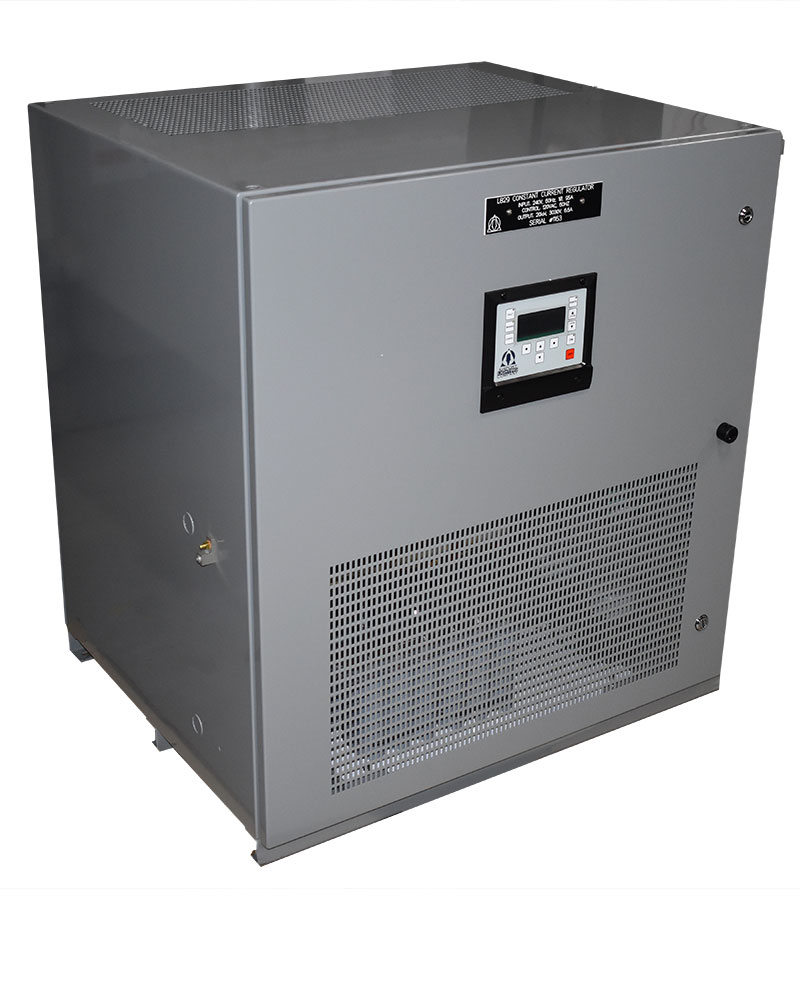
Image disclaimer: For identification and illustration only. It may show a product by another manufacturer and may not depict the exact item described; it is not a statement of any product’s quality, approval or performance. Third-party image and trademark rights belong to their owners. See full notice.
What Is It?
A Circuit Selector Switch (L‑847) is a specialised switching device used in AGL power distribution systems to direct the output of a Constant Current Regulator (CCR) to one of several series lighting circuits (e.g., runway edge, centreline, taxiway, approach). It provides the flexibility to share a single CCR among multiple lighting loads, reducing the number of regulators needed and enabling backup or redundancy schemes.
The L‑847 designation comes from FAA Advisory Circular 150/5345‑5 (currently Revision B), which specifies the performance and construction requirements for circuit selector switches used in airfield lighting — a separate AC from the one covering the CCR itself (AC 150/5345‑10, the L‑828 Constant Current Regulator spec). The switch is typically installed in the equipment shelter between the CCR output and the individual circuit feeders. It can be operated locally via a manual handle or remotely via a motor‑driven actuator controlled from the ALCMS or a control panel. The switch ensures that only one circuit is energised at a time, preventing conflicts and overloading, and it provides clear visual indication of which circuit is selected.
Purpose & Function
The L-847 switch exists to let a single CCR serve more than one lighting circuit, avoiding the cost and equipment-shelter space of dedicating a separate regulator to every runway, taxiway, or approach circuit at airfields where usage patterns don't require them to run simultaneously. Its purpose extends to redundancy as well as economy: if a CCR normally assigned to one circuit fails, the selector switch can redirect a working spare regulator to take over that circuit's load, providing a backup path without requiring a fully duplicated CCR for every single circuit in the system. Ensuring only one circuit is energised at any given time is itself a core part of the switch's purpose, since accidentally connecting a CCR's output to two circuits simultaneously would create an overload and current-sharing conflict the regulator isn't designed to handle.
Where Is It Used?
Circuit Selector Switches are installed in airfield electrical rooms, equipment shelters, or AGL power centres. They are used in various applications to optimise CCR utilisation and enhance system flexibility:
- Sharing a CCR Among Multiple Circuits: A single CCR can be used to power different lighting circuits at different times (e.g., runway edge lights during take‑off and taxiway lights during ground movement).
- Redundancy and Backup: In a redundant configuration, a standby CCR can be switched to any circuit if the primary CCR fails, ensuring continuity of critical lighting.
- Maintenance Isolation: The switch allows an individual circuit to be isolated for maintenance without affecting other circuits powered by the same CCR.
- Load Shedding: Non‑critical circuits can be deselected during generator operation to prioritise runway and approach lighting.
- Integration with ALCMS: Motorised selector switches can be remotely controlled from the ALCMS, enabling automated circuit selection based on operational needs or fault conditions.
Installation & Location
The switch is installed in the equipment shelter or electrical room between the CCR output terminals and the individual circuit feeders it serves, mounted on a panel or rack within reach of the CCRs it's associated with so the interconnecting cabling stays short and manageable. Each circuit feeder wired to the switch is clearly labelled at the point of termination, since a mislabelled position is a direct route to energising the wrong circuit, a mistake the switch's own interlocking is meant to prevent between circuits but can't catch if the wiring itself was connected incorrectly at installation. Where a motor-driven actuator is fitted, its control cabling is run back to the ALCMS or a local control panel alongside other AGL control wiring, kept identifiable so a remote circuit-selection command can be traced to the correct switch in an equipment room serving several CCRs and circuits. The switch's position indicator, whether a mechanical handle position or an electronic status readout, is mounted so it remains clearly visible to anyone working in the equipment room, giving an immediate visual check of which circuit is currently selected before any related maintenance work begins.
How Does It Work?
The Circuit Selector Switch consists of a multi‑position rotary switch or a set of interlocked contactors that route the CCR output to one of several load circuits. The switch has a common input (from the CCR) and multiple output terminals (each connected to a separate series circuit). A mechanical or electrical interlock prevents more than one output from being connected at a time.
Key functional aspects include:
- Manual Operation: A front‑panel rotary handle with clear position indicators allows the operator to select the desired circuit. The handle is typically spring‑loaded to ensure positive engagement.
- Remote Operation: Motor‑driven versions incorporate an electric actuator (often with position feedback) that can be controlled via dry contacts, Modbus, or other protocols from the ALCMS or a remote control panel.
- Position Indication: The switch provides local visual indication (pointer on the handle) and remote position status via auxiliary contacts or a communication interface.
- Interlocking: Electrical and mechanical interlocks prevent simultaneous connection of multiple circuits, protecting the CCR from overload and avoiding damage to the switch.
- Load Break Capability: The switch is designed to make and break the series circuit under load (up to the rated current, typically 6.6A or higher) without causing arcing or damage, complying with relevant switching standards.
One CCR, several circuits, only one connected at a time
CCR Output (Common Input)
Single feed arrives at the selector's common terminal
Selector Position
Rotary handle or motor-driven actuator selects one output; interlock blocks all others
Circuit 1 — connected, carries the full rated current
Circuit 2 — open, interlocked out
Circuit 3 — open, interlocked out
Position Feedback
Auxiliary contacts or comms report which circuit is active to the ALCMS
System Architecture & Control Logic
The selector switch sits between a single CCR and multiple candidate loops, so it is itself a control point rather than a passive component — ALCMS or an operator commands a position change, and the switch's own interlock (mechanical or electrical) is what prevents that command from ever connecting two circuits to one CCR simultaneously, protecting the regulator from paralleling loops of different impedance. Because only one circuit is powered at a time, any fault the CCR reports (voltage rise, no output) is unambiguously attributable to whichever circuit is currently selected — the switch's own position feedback is what lets ALCMS know which physical circuit a CCR-level alarm actually belongs to.
Physical Construction
The switch is built around a set of heavy-duty contactors or a motor-driven multi-position switch mechanism, sized to carry the full series-circuit current (commonly up to 20A) without significant contact resistance, since even a small added resistance in a constant-current loop shows up as an unwanted voltage rise the CCR has to compensate for. Contacts and busbars are housed in a metal cabinet with clear internal segregation between the different circuit paths being switched, preventing cross-connection between loops that must never be energised together. Where switching is motorised, a geared actuator drives the mechanism between positions under control-cable command, with mechanical position-indication contacts wired back to the ALCMS so the selected circuit routing can be confirmed remotely rather than only by physical inspection. The cabinet includes cable gland plates for the CCR input and each of the output circuit feeds, with a separate low-voltage compartment for the control and position-feedback wiring.
Technical Parameters
| Parameter | Typical Value |
|---|---|
| Rated Current | 6.6A to 20A (depending on model) |
| Rated Voltage | Up to 5 kV (open circuit voltage of CCR) |
| Number of Positions | 2 to 6 (commonly 3 or 4) |
| Operation | Manual (rotary handle) or motor‑driven (remote) |
| Interlock Type | Mechanical and electrical (anti‑simultaneous) |
| Load Break Capability | Rated to make/break the full series-circuit load (6.6A or 20A at up to 5 kV) without excessive arcing, per AC 150/5345-5 |
| Contact Material | Silver alloy or silver‑tungsten for arcing resistance |
| Auxiliary Contacts | 2–4 NO/NC contacts for position signalling |
| Enclosure | Indoor (NEMA 1, ~IP20) or outdoor (NEMA 4/4X, ~IP66) with weatherproofing |
| Standards | FAA AC 150/5345-5 (L-847), IEC 60947 |
Electrical Requirements
| Requirement | Typical Value |
|---|---|
| Circuit Type | In-line with the series airfield circuit, downstream of the CCR output |
| Rated Current | 6.6A to 20A (model dependent), continuous duty |
| Rated Voltage | Up to 5kV (CCR open-circuit voltage) |
| Interlock | Mechanical and electrical anti-simultaneous interlock prevents cross-connection between loops |
| Auxiliary Contacts | 2–4 NO/NC contacts wired to the CCR/ALCMS for position feedback |
| Cable/Terminal | L-824 cable entry glands, high-voltage rated terminal blocks |
| Insulation Resistance | Sized for 5kV service per IEC 60947 |
| Earthing/Grounding | Enclosure bonded to the airfield earth grid |
| Fault Protection | None internal — protection is provided upstream by the CCR; the switch is not itself a protective device |
| Actuator Supply (Motor-Driven) | 24VDC or 120/230VAC, separate from the switched high-voltage loop |
Applicable Standards
FAA AC 150/5345-5
Specification for L‑847 Circuit Selector Switch, 5,000 Volt, 6.6A/20A — covers performance and construction requirements for the switch itself
IEC 60947
Low‑voltage switchgear and controlgear — general requirements for switching devices
BS EN 60947-3
Switches, disconnectors, switch‑disconnectors and fuse‑combination units — applicable to selector switches
ICAO Annex 14
General requirements for AGL power distribution and control equipment
Installation Requirements
Panel/Rack Mounting Position
MechanicalMount the switch on a panel or rack within reach of the CCRs it's associated with, so interconnecting cabling to each stays short and manageable.
Circuit Feeder Labelling
ElectricalLabel each circuit feeder clearly at its point of termination before connecting, since a mislabelled position is a direct route to energising the wrong circuit.
Interlock Mechanism Verification
MechanicalConfirm the interlock mechanism physically prevents simultaneous connection of conflicting circuits before wiring is energised.
Feeder Termination & Torque
ElectricalTerminate feeder conductors at the switch's terminals to the specified torque value.
Position Feedback Wiring
ElectricalWire the switch's position feedback contacts back to the CCR or ALCMS monitoring point before commissioning.
Pre-Energisation Sign-off
DocumentationRecord feeder labelling, terminal torque values, and position feedback wiring as-built before energisation.
Testing & Commissioning
Insulation Resistance Test
Pre-EnergisationMegger each circuit position of the switch before the assembly is energised, confirming insulation resistance clears the acceptable minimum.
Interlock Function Test
Pre-EnergisationConfirm mechanical or electrical interlocks prevent an invalid or conflicting circuit selection.
Position Feedback Verification
InstallationConfirm the switch's position indication matches the actual contact position for every selectable circuit.
Contact Resistance Check
InstallationMeasure contact resistance for each switch position before the circuit is energised.
Switching Function Test
EnergisationCycle through every position with the CCR energised and confirm output is correctly routed to the selected circuit only.
Documentation & As-Built Sign-off
Final AcceptanceRecord insulation resistance, position feedback, and switching test results in the commissioning dossier.
Inspection & Maintenance
Contact Resistance & Wear Check
AnnualMeasure contact resistance across the silver or silver-tungsten contacts and inspect for arcing pits, since this switch breaks full load current.
Interlock Function Test
Semi-annualConfirm the mechanical and electrical interlock still prevents any two circuits from being selected simultaneously, protecting the CCR from paralleled loops.
Position Feedback Verification
Semi-annualCycle through each position and confirm auxiliary contacts or comms correctly report the active circuit to the ALCMS.
Actuator & Handle Operation Check
AnnualOperate the rotary handle or motor-driven actuator through its full range to confirm smooth, positive switching with no binding.
Insulation Resistance Test
AnnualMegger-test between circuits and to earth to confirm insulation withstand remains adequate for the CCR's open-circuit voltage.
Terminal & Connection Tightness Check
AnnualRe-torque incoming and outgoing terminal connections to spec, since loose terminations under load current can overheat.
Enclosure & Seal Inspection
AnnualFor outdoor-rated units, inspect enclosure gaskets and glands to confirm the rated IP66 (NEMA 4/4X) protection is intact.
Lubrication Check
AnnualInspect and, where specified by the manufacturer, re-lubricate moving contact and actuator surfaces to keep switching smooth and prevent seizure.
Common Field Issues
Contact Pitting and Wear
Repeated switching under load causes contact erosion. Over time, pitting increases contact resistance, leading to overheating and voltage drop. Regular inspection and replacement of contacts when worn is essential.
Mechanical Interlock Failure
The mechanical interlock mechanism can jam or break, potentially allowing two circuits to be connected simultaneously. This can cause the CCR to overload or damage the switch. Periodic mechanical inspection and lubrication are recommended.
Motor Actuator Malfunction
In motorised versions, the actuator motor, gearbox, or limit switches can fail, preventing remote operation or causing mis‑positioning. Regular testing and backup manual operation capability are critical.
Position Indication Errors
Auxiliary contacts or position sensors may fail or become misaligned, leading to incorrect status reporting to the ALCMS. This can cause confusion or unintended switching. Verify position feedback during routine maintenance.
Improper Sequencing
Switching from one circuit to another without de‑energising the CCR can cause arcing and contact damage. Proper control logic should ensure the CCR is turned off or its output is reduced before the switch is operated (unless designed for load break). Follow manufacturer guidance for safe operation.
Troubleshooting Guide
Switch Overheating or Showing Voltage Drop Across Contacts
Two Circuits Appear Energised Simultaneously, or Switch Jams
Motorised Switch Fails to Operate Remotely or Mis-Positions
Incorrect Position Reported to the ALCMS
Arcing or Contact Damage During Switching
Failure Modes & Root Causes
Contact Pitting and Wear
Interlock Mechanism Failure
Motorised Actuator Fault
Position Feedback Failure
Arc Damage from Live Switching
Safety & Operational Notes
Isolate Before Internal Work
Electrical SafetyDe-energise and lock out the CCR and all series circuits routed through the switch before working inside it, and verify zero energy before touching internal contacts.
Verify Interlock Before Manual Operation
Electrical SafetyConfirm the mechanical interlock is intact and functioning before manually cycling the switch; a jammed or worn interlock can leave two circuits appearing energised simultaneously or the switch itself jammed mid-position.
Confirm Selected Circuit Before Energising
OperationalPhysically verify which series circuit the switch is routed to before commanding the CCR on, rather than relying on remote status alone, since sending regulated current to the wrong circuit misdirects lighting guidance on the airfield.
Airside Work Coordination
OperationalAny switch operation that changes which circuit a CCR serves requires ATC/airside coordination and a NOTAM for the circuit(s) that will be dark or off-regulation during the transfer.
Insulation Test Before Re-Energisation
Electrical SafetyAfter any contact or wiring work, megger test the affected circuit paths before restoring power, since a residual fault at re-energisation can trip the CCR or damage healthy fixtures on the newly connected loop.
PPE & Grounding
Personnel SafetyUse insulated tools and appropriate PPE when working on switch contacts, and confirm the enclosure is bonded/grounded per the electrical design before reconnecting a circuit.
Motorised Actuator Verification
VerificationOn motorised versions, confirm the actuator drives fully to each commanded position and the limit switches register correctly, since a fault here can leave the switch mis-positioned without an obvious external sign.
Restore to Compliant State
ComplianceConfirm the switch is in its intended position, the interlock is fully functional, and the correct circuit is energised before closing out the work and cancelling any associated NOTAM.
Engineering & Expert Notes
The Make-Before-Break vs Break-Before-Make Behaviour Needs to Be Known, Not Assumed
DesignWhether an L-847 switch briefly connects two circuits together during transfer or briefly de-energises both matters for how it interacts with downstream protection and with any interlocked equipment; confirm the specific switch's transfer behaviour against the system design intent rather than assuming a generic selector switch behaves one particular way.
Verify Visual Position Indication Matches Actual Contact Position
VerificationA mechanical position indicator can become misaligned relative to the actual internal contact position after years of operation or a maintenance intervention, showing a circuit as selected when it isn't actually energised through that path; periodically verify the indicator against an independent electrical check rather than trusting the pointer alone.
Motor-Driven Actuators Need Their Own Maintenance Attention
MaintenanceWhere the switch is remotely operated via a motor-driven actuator, the actuator's own mechanical condition — gearing, limit switches, coupling to the switch shaft — needs periodic attention distinct from the switch contacts themselves; an actuator fault can leave the switch stuck mid-travel even though the switch mechanism itself is in good condition.
Never Switch a Loaded Series Circuit Without Confirming It's the Right Type of Switch for the Job
SafetyNot every circuit selector switch is rated for load-break operation; some designs require the CCR to be de-energised or the circuit to be otherwise unloaded before switching. Confirm the specific switch's load-break rating before operating it under load, since attempting to switch a loaded circuit on a non-load-break-rated unit can damage the switch or create an arcing hazard.
Exercise Switches on Circuits That Rarely Get Reassigned
ReliabilityA selector switch dedicated to a backup or rarely-used routing option can sit in one position for years without being exercised, allowing contacts on the unused positions to develop resistance or a mechanism to stiffen; periodically cycle through all positions as a planned maintenance activity rather than only operating the switch when an actual reroute is needed.
Document the As-Left Position After Every Manual Operation
DocumentationA circuit selector switch operated manually during an emergency or maintenance action and then left in a non-standard position without clear documentation can cause confusion for the next person working on the system; record and communicate the as-left switch position any time it's manually changed from its normal operating configuration.
Frequently Asked Questions
Short answers about the L-847 circuit selector switch: what it is, how it works, specifications, standards, maintenance and common faults.
Q1What is an L-847 circuit selector switch?
An L-847 circuit selector switch is a switching device that directs the output of a constant current regulator (CCR) to one of several series lighting circuits, such as runway edge, centreline, taxiway or approach. It lets one CCR be shared among multiple loads and supports backup and redundancy schemes.
Q2Where does the L-847 designation come from?
From FAA Advisory Circular 150/5345-5 (currently Revision B), the specification for circuit selector switches, 5,000 volt, 6.6 A/20 A. It is a separate AC from the one covering the CCR itself (AC 150/5345-10, the L-828 regulator specification).
Q3Where is the switch installed?
Typically in the equipment shelter between the CCR output and the individual circuit feeders, in airfield electrical rooms and AGL power centres.
Q4How does the switch work?
It is a multi-position rotary switch or a set of interlocked contactors with one common input from the CCR and several outputs, each feeding a separate series circuit. A mechanical or electrical interlock prevents more than one output from being connected at a time.
Q5Can it be operated remotely?
Yes. Manual versions use a front-panel rotary handle with position indicators. Motor-driven versions use an electric actuator for remote operation, with 2 to 4 auxiliary contacts giving position feedback to the CCR or ALCMS.
Q6What are the typical ratings?
Rated current 6.6 A to 20 A and voltage up to 5 kV (the CCR open-circuit voltage), with 2 to 6 positions (commonly 3 or 4). It is rated to make and break the full series-circuit load without excessive arcing per AC 150/5345-5.
Q7Does the selector switch protect the circuit?
No. It has no internal protection and is not itself a protective device, as protection is provided upstream by the CCR.
Q8Which standards apply?
The main references are FAA AC 150/5345-5 (L-847), IEC 60947, BS EN 60947-3 and ICAO Annex 14. Always verify the current edition and your aerodrome's approved requirements.
Q9How often should the switch be inspected?
Typical intervals are semi-annual for interlock function test and position feedback verification, and annual for contact resistance and wear, actuator and handle operation, insulation resistance, terminal tightness, enclosure and seal inspection and lubrication. Your airport's approved maintenance programme takes precedence.
Q10What are the common problems with L-847 switches?
Common problems are contact pitting and wear, mechanical interlock failure, motor actuator malfunction, position indication errors and improper sequencing. Two circuits appearing energised at once, a jammed switch, overheating or arcing during switching all need prompt attention.
Related Components
Go Beyond the Component. Understand the Complete AGL System.
You have explored the component. Now understand how it works within the complete Airfield Ground Lighting system.
Learn AGL from fundamentals to design, installation, testing, photometry, commissioning, maintenance and troubleshooting through structured technical training at Precision AGL Academy.
Build practical knowledge. Understand the circuit. Read the standards. Troubleshoot with confidence.
Your next step in AGL starts here.
Need expert guidance on circuit selector switch selection, integration, or maintenance?
Precision AGL Academy provides advice on L‑847 compliant switches, motorised actuator selection, and integration with ALCMS for flexible circuit allocation.
Follow the Academy
Important Notice, Disclaimer & Limitation of Liability
Please read before relying on any content on this page.
- Purpose and intended users. This page on Circuit Selector Switch (L-847) is an independent educational and informational reference for competent, suitably trained and authorised airfield ground lighting (AGL) and aerodrome electrical personnel. It is not professional engineering, legal or regulatory advice, and using it does not create any professional or client relationship.
- Safety. Work on series circuits, constant current regulators (CCRs), isolating transformers, cables, connectors and lighting equipment can be fatal. Always apply the aerodrome’s permit-to-work and isolation/LOTO procedures, prove dead, use correctly rated instruments and PPE, and follow the manufacturer’s instructions. Nothing here authorises work on live equipment or the bypassing of any safety device or interlock.
- Aviation operations. Nothing here authorises installation, modification, energisation, adjustment, return to service, a change of operating category (CAT I/II/III), a NOTAM or any aerodrome certification or approval decision. These rest with the aerodrome operator, the air navigation service provider and the competent regulator.
- Specifications, ratings and typical values. Descriptions, parameters, ratings, dimensions, photometric values, wattages, service lives, maintenance tasks and intervals, failure modes, certifications (for example CE, FCC, UL or IEC marks) and part or type designations are general, typical and indicative. They may not match any particular product, make, model or version, and they are not a datasheet, design, specification, selection, sizing, procurement or acceptance criterion. The manufacturer’s current documents, the approved design and the project specification prevail.
- Standards and regulations. References to ICAO, FAA, IEC, IEEE, ISO, BIS, DGCA and other standards are paraphrased summaries for orientation only. They may be incomplete or out of date, and standards are revised from time to time. Consult the current official editions. Following this content does not guarantee compliance with any law, standard or regulatory approval, and the regulator’s requirements always prevail.
- No warranty. Content is provided “as is” and “as available”, without warranty of any kind, express or implied, including accuracy, completeness, currency or fitness for a particular purpose. Real installations differ in design, equipment make and model, age and condition.
- Limitation of liability. To the fullest extent permitted by applicable law, Precision AGL Academy, Precision AGL Solutions and their owners, authors and contributors are not liable for any injury, death, loss, damage, downtime, penalty or regulatory consequence, whether direct or indirect, arising from the use of, reliance on, or inability to use this content. Nothing in this notice excludes or limits any liability that cannot lawfully be excluded or limited.
- Independence, brands and no endorsement. This is an independent publication. It is not affiliated with, sponsored by or endorsed by ICAO, the FAA, the IEC, DGCA, AAI, any airport, regulator, supplier or equipment manufacturer. Third-party names, product designations, standard designations and trademarks (including Megger®, Siemens, Eaton, Crouse-Hinds, ADB SAFEGATE, Fluke, ABB and Honeywell) belong to their respective owners and are used only for identification and description. Mention of a brand, product or supplier is not a recommendation, and we do not sell, supply or quote for any component described.
- Images and third-party content. Images and illustrations are shown to help identify the type of component. They may show products of various manufacturers, may not depict the exact item described, and are not a statement about any product’s quality, approval or performance. Copyright and trademarks in third-party images, logos and photographs belong to their respective owners and are not claimed as ours. If you are a rights holder and want an image removed, replaced or credited, email precisionaglsolutions@gmail.com with the page address and we will act promptly.
- Training and services. Mentions of training, courses, consultation, advice, selection, installation, calibration or other support, including the “Learn…Certify” pathway, describe learning stages and are not an offer, quotation, tender or promise of any result. Contacting us or our replying creates no engagement or duty of care; an engagement exists only under a written agreement. We are not a regulator or certification body, and completing any course or reading this content is not a certification, accreditation or authorisation to work on any aerodrome.
- Copyright, privacy and corrections. © 2026 Precision AGL Academy. All rights reserved. Text, structure, compilations and diagrams may be viewed for personal reference and internal training only; any other copying, republication or commercial use needs our written permission. If you email, telephone or message us, we use your details only to respond and handle your matter, in line with applicable Indian law including the Digital Personal Data Protection Act, 2023; please do not send confidential or security-sensitive information. To display this page your browser requests fonts, icons and images from third-party servers, which receive your IP address and browser details under their own policies. Content is reviewed periodically with no obligation to update. To report an error, safety concern or rights issue, write to precisionaglsolutions@gmail.com.