Communication Gateway
The universal protocol translator that bridges disparate communication systems in modern AGL networks. A Communication Gateway enables seamless data exchange between legacy serial protocols (Modbus RTU, Profibus) and modern IP-based networks (Ethernet/IP, Modbus TCP, OPC UA), ensuring interoperability across the entire airfield lighting infrastructure.
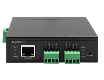
Image disclaimer: For identification and illustration only. It may show a product by another manufacturer and may not depict the exact item described; it is not a statement of any product’s quality, approval or performance. Third-party image and trademark rights belong to their owners. See full notice.
What Is It?
A Communication Gateway (also known as a protocol gateway or protocol converter) is a network device that enables communication between systems using different protocols, data formats, or physical media. In AGL applications, the gateway serves as the central protocol translation hub, bridging the gap between legacy fieldbus networks (such as Modbus RTU, Profibus DP, and serial RS‑485) and modern IP-based networks (including Ethernet/IP, Profinet, Modbus TCP, and OPC UA). This allows older CCRs, Remote I/O units, and sensors with serial interfaces to be integrated into the modern ALCMS without costly equipment replacement. The gateway performs protocol conversion, data mapping, and often includes advanced functions such as data aggregation, buffering, alarm handling, and cybersecurity features (firewall, VPN, authentication). It is the key enabler for mixed-vendor, multi‑protocol airfield control systems, providing a unified data model for the entire AGL infrastructure.
Purpose & Function
The communication gateway exists to solve a very practical airfield problem: an AGL system installed over decades will inevitably contain a mix of legacy fieldbus equipment and modern IP-based devices, and replacing every older CCR or sensor just to standardise on one protocol would be prohibitively expensive and operationally disruptive. The gateway lets that mixed-vintage equipment coexist on one coherent network by translating between the different languages the various devices speak.
This matters directly for system reliability and security: without a controlled translation point, integrating old and new equipment ad hoc risks introducing communication gaps or unmonitored access points. By consolidating protocol conversion, data mapping, and cybersecurity functions like firewalling and authentication into a single hub, the gateway gives an airfield a defensible, unified point of control over its entire mixed-protocol data flow.
Where Is It Used?
Communication gateways are deployed in all areas where protocol translation is required, including:
- Legacy CCR Integration: Bridging older Modbus RTU or Profibus-based CCRs to a modern Ethernet/IP or Modbus TCP ALCMS network.
- Remote I/O Networks: Converting serial fieldbus (Profibus, DeviceNet) to Ethernet-based protocols for connection to the main PLC or SCADA system.
- ALCMS Interface: Providing a standardized data interface (OPC UA, MQTT) between the AGL control system and higher-level airport SCADA, building management, or IoT platforms.
- RWSL (Runway Status Light) Systems: Integrating sensors and controllers with different communication interfaces into a unified control network.
- Sensor Integration: Connecting weather stations, wind sensors, and visibility sensors that use proprietary or serial protocols to the IP-based network.
- Multi‑vendor Environments: Enabling seamless data exchange between equipment from different manufacturers that use different industrial protocols.
- Remote Substations: Aggregating data from multiple serial devices at a substation and converting to a single Ethernet uplink to the control room.
- Cybersecurity Zones: Acting as a secure edge gateway with firewall and VPN capabilities to protect the AGL network from external threats.
Installation & Location
Gateways are DIN-rail or rack-mounted inside the field cabinet, substation, or control room where the two networks being bridged both terminate, positioned close to the field-side wiring (CCR, Remote I/O, or fieldbus devices) it serves so the legacy-protocol cable run stays short. Enclosure selection depends on location: a hardened, sealed unit for an outdoor runway-edge cabinet, a standard panel-mount unit for an indoor substation or control room. Power is typically fed from the same DC supply as the PLC or Remote I/O it's paired with, and its network-side connection runs on structured Ethernet cabling back to the nearest switch rather than sharing conduit with the legacy fieldbus wiring on its field side.
How Does It Work?
The Communication Gateway operates as a protocol translation engine, performing several key functions to enable seamless data exchange:
- Protocol Conversion: The gateway decodes data packets from one protocol (e.g., Modbus RTU) and re-encodes them into another protocol (e.g., Modbus TCP or Ethernet/IP), preserving the data content while transforming the framing, addressing, and data representation.
- Data Mapping: The gateway maps data points from the source protocol's address space (e.g., Modbus registers) to the target protocol's object model (e.g., OPC UA nodes or Ethernet/IP tags), creating a unified data model for the entire system.
- Buffering and Caching: The gateway can buffer data from slow serial devices, presenting a consistent data view to faster IP-based clients, and reducing the polling load on legacy field devices.
- Alarm and Event Handling: Advanced gateways can detect alarm conditions (e.g., value out of range, communication loss) and generate standardized alarm notifications (e.g., OPC UA Alarms & Conditions, SNMP traps).
- Cybersecurity: The gateway often includes a built-in firewall, access control lists, authentication mechanisms (IEEE 802.1X, RADIUS), and VPN client/server capabilities to secure communication and protect the AGL network from unauthorized access.
- Diagnostics and Logging: The gateway maintains logs of communication events, errors, and performance metrics, supporting proactive maintenance and troubleshooting.
Gateways are typically configured via a web interface or dedicated software tool, where users define the protocol parameters, data mapping tables, and network settings.
System Architecture & Control Logic
The Communication Gateway sits at the boundary between the legacy or vendor-specific field network and the IP-based ALCMS backbone. On the field side it speaks whatever protocol the older CCRs, PLCs, or third-party equipment use — commonly Modbus RTU/ASCII, DNP3, or a proprietary serial link — polling or listening for status and accepting commands in that native format. On the ALCMS side it re-publishes the same data as OPC UA, Modbus TCP, or another standard IP protocol over the Ethernet backbone, so the ALCMS server sees a uniform data model regardless of what is actually installed in the field. Because it sits directly in this path, a gateway fault or protocol mismatch isolates the ALCMS from an entire branch of field equipment even though the equipment itself is functioning normally, which is why gateway health is monitored as its own point in the architecture.
Legacy / Vendor Field Devices
CCRs, PLCs or third-party controllers on serial or proprietary links (Modbus RTU, DNP3)
Communication Gateway
Protocol translation & data model mapping
ALCMS Backbone
Ethernet Switch → ALCMS Server (OPC UA / Modbus TCP)
How the Gateway Bridges Two Protocols
Source Protocol Device
e.g., legacy Modbus RTU field device on a serial bus
Packet Decoded
Data extracted from the source protocol's framing & addressing
Data Mapped to Target Model
Registers translated to OPC UA nodes or Ethernet/IP tags
Packet Re-Encoded
Re-framed in the target protocol (e.g., Modbus TCP, Ethernet/IP)
Delivered to IP Client
Buffered/cached for a consistent view, reducing polling load on legacy devices
Standardized Alarm Generated
Value out of range or comms loss → OPC UA A&C event or SNMP trap
Physical Construction
The gateway is housed in a compact extruded-aluminium or steel enclosure designed for DIN-rail mounting inside a control cabinet, with a conformally coated internal circuit board to resist dust, humidity, and airborne contaminants in unconditioned equipment rooms. Serial and Ethernet ports are brought out through the front or top face with keyed, panel-mounted connectors, and where fibre SFP slots are fitted, the cage is soldered directly to the board and accessed through a dedicated cutout. Where the unit is deployed in a field-mount enclosure rather than a control cabinet, the housing is upgraded to a sealed IP65 box with cable glands for each conductor entry, keeping the internal electronics isolated from moisture. The dual power inputs terminate at screw-clamp terminals rated for the 24 VDC nominal supply, and the enclosure includes a chassis earth stud for bonding to the cabinet ground bus.
Technical Parameters
| Parameter | Typical Value |
|---|---|
| Supported Protocols (Serial) | Modbus RTU, Profibus DP, DeviceNet, CANopen, RS‑232/485 (ASCII), DF1 |
| Supported Protocols (Ethernet) | Modbus TCP, Ethernet/IP, Profinet, OPC UA, MQTT, BACnet/IP, SNMP |
| Port Configuration | 2-4 serial ports (RS‑232/485), 2-4 Ethernet ports (10/100/1000BASE-T), optional SFP fiber slots |
| Data Mapping Capacity | Up to 10,000 data points (configurable) |
| Throughput | Up to 1,000 transactions/second (depending on configuration) |
| Cybersecurity Features | Firewall, VPN (IPsec/OpenVPN), IEEE 802.1X, RADIUS, HTTPS, SSH, access control lists |
| Alarm Management | OPC UA Alarms & Conditions, SNMP traps, email alerts |
| Power Supply | 24 VDC (nominal, 18‑32 VDC) with dual redundant inputs |
| Power Consumption | 5‑25 W (depending on model and load) |
| Operating Temperature | -40°C to +70°C (industrial grade) |
| Storage Temperature | -40°C to +85°C |
| Protection Class | IP30 (panel mount), IP40 (ruggedized), IP65 (field mount with enclosure) |
| Mounting | DIN rail (standard) or panel mount |
| Configuration | Web GUI, command-line interface (CLI), or dedicated configuration software |
| Diagnostics | Status LEDs, system log, port statistics, SNMP traps |
| Certifications | CE, FCC, UL, IEC 61000‑6‑2 (EMC immunity) |
Electrical Requirements
| Requirement | Typical Value |
|---|---|
| Circuit Position | Standalone powered networking device, field or control-room mounted |
| Power Supply | 24 VDC (nominal, 18‑32 VDC) with dual redundant inputs |
| Power Consumption | 5‑25 W (depending on model and load) |
| Isolation | Powered separately from the AGL series circuit; data-only interface to field devices |
| Earthing | Enclosure bonded to local earth |
| Fault Protection | Dual-input redundancy with internal overcurrent protection |
Applicable Standards
IEC 61158
Industrial communication networks — Fieldbus specifications
IEC 62541 (OPC UA)
OPC Unified Architecture — platform-independent communication
IEC 62443
Industrial communication networks — network and system security
FAA AC 150/5345‑56
Specification for L-890 Airport Lighting Control and Monitoring System (ALCMS)
Installation Requirements
Enclosure Selection
CivilSelect a hardened, sealed enclosure for an outdoor runway-edge cabinet or a standard panel-mount unit for an indoor substation or control room, matching the gateway's installed environment.
DIN-Rail or Rack Mounting
MechanicalMount the gateway close to the field-side wiring it serves — CCR, Remote I/O, or fieldbus devices — so the legacy-protocol cable run stays short.
Shared DC Power Feed
ElectricalFeed power from the same DC supply as the PLC or Remote I/O the gateway is paired with, confirming voltage and loading before connecting the field-side wiring.
Segregated Cable Routing
ElectricalRun the network-side connection on structured Ethernet cabling back to the nearest switch, kept separate from the legacy fieldbus wiring on the field side.
Protocol Configuration & Mapping
DocumentationConfigure and verify the protocol translation mapping between the two networks being bridged before the gateway is relied on for live data.
Pre-Commissioning Sign-off
DocumentationRecord enclosure type, power feed, and cable routing as-built before commissioning testing begins.
Testing & Commissioning
Protocol Conversion Verification
CommissioningConfirm data correctly translates between the legacy fieldbus protocol and the IP-based network in both directions.
Data Mapping Verification
CommissioningConfirm each field point maps to the correct register or tag on the ALCMS side, point by point.
Serial Port Parameter Verification
Pre-CommissioningConfirm baud rate, parity, and other serial parameters match the connected field devices before enabling the link.
Latency & Timeout Test
CommissioningMeasure round-trip latency under load and confirm it stays within the tolerance the control loop requires.
Failover / Redundancy Test
CommissioningWhere a redundant gateway is fitted, simulate a failure and confirm seamless handover to the standby unit.
Security Configuration Verification
Pre-CommissioningConfirm firewall, VPN, and authentication settings match the design before the gateway is connected to the live network.
Power Supply & UPS Check
Pre-CommissioningConfirm the gateway operates correctly on both primary and backup power sources.
Documentation & As-Built Sign-off
Final AcceptanceRecord protocol mapping, latency, and security configuration in the commissioning dossier for handover.
Inspection & Maintenance
Data Mapping Verification
Semi-annualRe-validate register addresses, data types, and scaling factors against connected devices, especially after firmware updates or field device swaps.
Serial Port Parameter Check
AnnualConfirm baud rate, parity, stop bits, and data bits still match each connected serial device to prevent garbled data or dropped comms.
Latency & Timeout Audit
QuarterlyReview polling rates and timeout margins against actual device response times, adjusting for any legacy equipment added to the loop.
Firmware Update Review
QuarterlyCheck for gateway firmware releases and compatibility matrix changes, testing updates on a bench unit before applying in the field.
Security Configuration Audit
QuarterlyVerify default credentials remain changed, unused services are disabled, and network segmentation rules are still correctly applied.
Power Supply & UPS Check
Semi-annualMeasure the 24 VDC supply for stability and test UPS backup runtime to guard against resets or data corruption during voltage dips.
Cable & Connector Inspection
AnnualExamine serial and network cabling, terminals, and connectors for corrosion or loose contacts, a common cause of intermittent comms faults.
Diagnostic Log Review
MonthlyReview the gateway's error and event logs for recurring communication faults or protocol errors before they escalate into outages.
Common Field Issues
Incorrect Data Mapping Configuration
Misconfigured register addresses, data types, or scaling factors can cause incorrect values to be reported (e.g., current readings showing wrong values). Thorough validation and testing of data mapping tables is essential before commissioning.
Serial Communication Parameters Mismatch
Baud rate, parity, stop bits, and data bits must match between the gateway and the serial device. A mismatch results in garbled data or no communication. Verify settings against device specifications.
Network Timing & Timeout Issues
Slow serial devices may not respond within the gateway's timeout window, causing communication errors. Adjust timeout settings and consider using a slower polling rate to accommodate legacy equipment.
Firmware Incompatibility
Gateway firmware versions may not support all protocol variants or features of connected devices. Always check compatibility matrices and update firmware if necessary.
Cybersecurity Vulnerabilities
Gateways with exposed web interfaces or default credentials can be attacked. Change default passwords, disable unused services, and implement network segmentation to protect critical AGL control data.
Power Supply Instability
Gateways, like all industrial electronics, are sensitive to voltage fluctuations. Use a dedicated, regulated 24 VDC power supply with UPS backup to prevent resets or data corruption.
Troubleshooting Guide
Values Reported Are Wrong But Communication Is Established
Garbled Data or No Communication on a Serial Device
Intermittent Communication Errors with a Legacy Device
Connected Device's Full Feature Set Not Supported
Unauthorised Access or Configuration Change Detected
Gateway Resets or Data Corruption During Power Events
Failure Modes & Root Causes
Data Mapping Configuration Error
Serial Communication Parameter Mismatch
Polling Timeout Mismatch with Legacy Devices
Firmware / Protocol Incompatibility
Unauthorised Access
Power Supply Instability
Safety & Operational Notes
Isolate Both Redundant Power Inputs
Electrical SafetyWhere the gateway is fed by dual redundant 24VDC inputs, isolate and verify zero energy on both before internal work, since disconnecting only one leaves the unit powered from the other.
ESD-Sensitive Electronics
OperationalUse anti-static precautions when handling the gateway's internal protocol-conversion boards or communication interface modules.
Coordinate Before Taking Down Protocol Translation
OperationalThe gateway may be the only bridge between legacy fieldbus-connected CCRs/sensors and the IP-based ALCMS network; confirm what monitoring or control capability is lost before isolating it, and coordinate with control-room operators accordingly.
Firmware/Configuration Change Control
ComplianceMake firmware updates or protocol-mapping changes only under an authorised change-control process, and verify each connected legacy device is still correctly represented on the IP side afterward.
Restore to Compliant State
ComplianceConfirm data is passing correctly in both directions between the legacy and IP-based networks before closing out the work and returning the gateway to unattended operation.
Engineering & Expert Notes
Version-Control the Data Mapping Table Like Firmware
ConfigurationA gateway's register-to-tag mapping table is as critical to correct operation as its firmware, yet it's often changed informally during troubleshooting and never re-documented. Treat mapping table edits with the same change-control discipline as firmware updates, since an undocumented mapping change is one of the hardest faults to trace months later.
Legacy Serial Devices Set the Polling Ceiling
PerformanceA gateway can support fast IP-side polling while the legacy serial device on the other side simply cannot respond that quickly; forcing a fast poll rate against a slow legacy device produces intermittent timeouts that look like a gateway fault but are actually a mismatch with the field device's real response time. Set poll rates to the slowest device on a given port, not the gateway's maximum capability.
Default Credentials Are the Most Common Real-World Breach Point
CybersecurityGateways are frequently commissioned with vendor default passwords left in place because the installer's focus was on getting protocol conversion working, not securing the web interface. Change default credentials and disable unused services as a mandatory commissioning step, verified independently of functional testing.
Serial Parameter Mismatches Masquerade as Intermittent Faults
TroubleshootingA baud rate or parity mismatch doesn't always produce a hard failure; it can intermittently succeed on short messages and fail on longer ones, making the fault look like a flaky cable rather than a configuration error. Verify serial parameters against the device datasheet as a first troubleshooting step whenever a serial-connected device reports intermittent, rather than constant, communication loss.
Firmware Compatibility Isn't Symmetric
MaintenanceA gateway firmware update that adds support for a new protocol variant can simultaneously change default behaviour on an existing, previously working connection. Check the compatibility matrix and changelog against every currently connected device type before updating, not just the device the update was intended to support.
Segregate Legacy Fieldbus Traffic From the IP Backbone
Network DesignRunning converted legacy protocol traffic over the same VLAN as general IP traffic without segmentation means a broadcast storm or misbehaving IP device elsewhere on the network can starve time-sensitive lighting control messages. Keep the gateway's IP-side connection on a dedicated or prioritised VLAN rather than sharing it with general-purpose network traffic.
Frequently Asked Questions
Short answers about the Communication Gateway: what it is, how it works, typical specifications, standards, maintenance and common faults.
Q1What is a Communication Gateway?
A Communication Gateway (also known as a protocol gateway or protocol converter) is a network device that enables communication between systems using different protocols, data formats, or physical media. In AGL applications, the gateway serves as the central protocol translation hub, bridging the gap between legacy fieldbus networks (such as Modbus RTU, Profibus DP, and serial RS‑485) and modern IP-based networks (including Ethernet/IP, Profinet, Modbus TCP, and OPC UA).
Q2What is the purpose of a Communication Gateway?
The communication gateway exists to solve a very practical airfield problem: an AGL system installed over decades will inevitably contain a mix of legacy fieldbus equipment and modern IP-based devices, and replacing every older CCR or sensor just to standardise on one protocol would be prohibitively expensive and operationally disruptive. The gateway lets that mixed-vintage equipment coexist on one coherent network by translating between the different languages the various devices speak.
Q3Where is a Communication Gateway used and installed?
Communication gateways are deployed in all areas where protocol translation is required, including: Legacy CCR Integration: Bridging older Modbus RTU or Profibus-based CCRs to a modern Ethernet/IP or Modbus TCP ALCMS network. Remote I/O Networks: Converting serial fieldbus (Profibus, DeviceNet) to Ethernet-based protocols for connection to the main PLC or SCADA system. ALCMS Interface: Providing a standardized data interface (OPC UA, MQTT) between the AGL control system and higher-level airport SCADA, building management, or IoT platforms.
Q4How does a Communication Gateway work?
The Communication Gateway operates as a protocol translation engine, performing several key functions to enable seamless data exchange: Protocol Conversion: The gateway decodes data packets from one protocol (e.g., Modbus RTU) and re-encodes them into another protocol (e.g., Modbus TCP or Ethernet/IP), preserving the data content while transforming the framing, addressing, and data representation.
Q5What are the typical technical parameters of a Communication Gateway?
Typical values are — Supported Protocols (Serial): Modbus RTU, Profibus DP, DeviceNet, CANopen, RS‑232/485 (ASCII), DF1; Supported Protocols (Ethernet): Modbus TCP, Ethernet/IP, Profinet, OPC UA, MQTT, BACnet/IP, SNMP; Port Configuration: 2-4 serial ports (RS‑232/485), 2-4 Ethernet ports (10/100/1000BASE-T), optional SFP fiber slots; Data Mapping Capacity: Up to 10,000 data points (configurable); Throughput: Up to 1,000 transactions/second (depending on configuration); Cybersecurity Features: Firewall, VPN (IPsec/OpenVPN), IEEE 802.1X, RADIUS, HTTPS, SSH, access control lists; Alarm Management: OPC UA Alarms & Conditions, SNMP traps, email alerts.
Q6What are the electrical requirements for a Communication Gateway?
Typical requirements are — Circuit Position: Standalone powered networking device, field or control-room mounted; Power Supply: 24 VDC (nominal, 18‑32 VDC) with dual redundant inputs; Power Consumption: 5‑25 W (depending on model and load); Isolation: Powered separately from the AGL series circuit; data-only interface to field devices; Earthing: Enclosure bonded to local earth; Fault Protection: Dual-input redundancy with internal overcurrent protection.
Q7Which standards apply to a Communication Gateway?
The main references are IEC 61158 — Industrial communication networks — Fieldbus specifications; IEC 62541 (OPC UA) — OPC Unified Architecture — platform-independent communication; IEC 62443 — Industrial communication networks — network and system security; FAA AC 150/5345‑56 — Specification for L-890 Airport Lighting Control and Monitoring System (ALCMS). Always verify the current edition and your aerodrome's approved requirements.
Q8How often should a Communication Gateway be inspected and maintained?
Typical maintenance tasks and intervals are: Data Mapping Verification (semi-annual); Serial Port Parameter Check (annual); Latency & Timeout Audit (quarterly); Firmware Update Review (quarterly); Security Configuration Audit (quarterly); Power Supply & UPS Check (semi-annual); Cable & Connector Inspection (annual); Diagnostic Log Review (monthly). Your airport's approved maintenance programme takes precedence.
Q9How do I troubleshoot common Communication Gateway faults?
Common symptoms covered are: Values Reported Are Wrong But Communication Is Established; Garbled Data or No Communication on a Serial Device; Intermittent Communication Errors with a Legacy Device; Connected Device's Full Feature Set Not Supported; Unauthorised Access or Configuration Change Detected; Gateway Resets or Data Corruption During Power Events. For example, for "Values Reported Are Wrong But Communication Is Established": Likely Cause: A misconfigured register address, data type, or scaling factor in the data mapping table, since the gateway is successfully exchanging data but translating it incorrectly. Diagnostic Steps: Cross-check the affected point's mapping table entry (register address, data type, scaling) against the source device's documentation; compare the raw register value to the translated output to identify where the error is introduced. Corrective Action: Correct the mapping table entry and re-validate against the device specification; re-test the specific point before considering it resolved, since a scaling error can affect multiple points from the same table.
Related Components
Go Beyond the Component. Understand the Complete AGL System.
You have explored the component. Now understand how it works within the complete Airfield Ground Lighting system.
Learn AGL from fundamentals to design, installation, testing, photometry, commissioning, maintenance and troubleshooting through structured technical training at Precision AGL Academy.
Build practical knowledge. Understand the circuit. Read the standards. Troubleshoot with confidence.
Your next step in AGL starts here.
Need expert guidance on Communication Gateway selection, protocol integration, or cybersecurity for your AGL system?
Precision AGL Academy provides advice on protocol mapping, device integration, network security, and field commissioning for mixed-protocol environments.
Follow the Academy
Important Notice, Disclaimer & Limitation of Liability
Please read before relying on any content on this page.
- Purpose and intended users. This page on Communication Gateway is an independent educational and informational reference for competent, suitably trained and authorised airfield ground lighting (AGL) and aerodrome electrical personnel. It is not professional engineering, legal or regulatory advice, and using it does not create any professional or client relationship.
- Safety. Work on series circuits, constant current regulators (CCRs), isolating transformers, cables, connectors and lighting equipment can be fatal. Always apply the aerodrome’s permit-to-work and isolation/LOTO procedures, prove dead, use correctly rated instruments and PPE, and follow the manufacturer’s instructions. Nothing here authorises work on live equipment or the bypassing of any safety device or interlock.
- Aviation operations. Nothing here authorises installation, modification, energisation, adjustment, return to service, a change of operating category (CAT I/II/III), a NOTAM or any aerodrome certification or approval decision. These rest with the aerodrome operator, the air navigation service provider and the competent regulator.
- Specifications, ratings and typical values. Descriptions, parameters, ratings, dimensions, photometric values, wattages, service lives, maintenance tasks and intervals, failure modes, certifications (for example CE, FCC, UL or IEC marks) and part or type designations are general, typical and indicative. They may not match any particular product, make, model or version, and they are not a datasheet, design, specification, selection, sizing, procurement or acceptance criterion. The manufacturer’s current documents, the approved design and the project specification prevail.
- Standards and regulations. References to ICAO, FAA, IEC, IEEE, ISO, BIS, DGCA and other standards are paraphrased summaries for orientation only. They may be incomplete or out of date, and standards are revised from time to time. Consult the current official editions. Following this content does not guarantee compliance with any law, standard or regulatory approval, and the regulator’s requirements always prevail.
- No warranty. Content is provided “as is” and “as available”, without warranty of any kind, express or implied, including accuracy, completeness, currency or fitness for a particular purpose. Real installations differ in design, equipment make and model, age and condition.
- Limitation of liability. To the fullest extent permitted by applicable law, Precision AGL Academy, Precision AGL Solutions and their owners, authors and contributors are not liable for any injury, death, loss, damage, downtime, penalty or regulatory consequence, whether direct or indirect, arising from the use of, reliance on, or inability to use this content. Nothing in this notice excludes or limits any liability that cannot lawfully be excluded or limited.
- Independence, brands and no endorsement. This is an independent publication. It is not affiliated with, sponsored by or endorsed by ICAO, the FAA, the IEC, DGCA, AAI, any airport, regulator, supplier or equipment manufacturer. Third-party names, product designations, standard designations and trademarks (including Megger®, Siemens, Eaton, Crouse-Hinds, ADB SAFEGATE, Fluke, ABB and Honeywell) belong to their respective owners and are used only for identification and description. Mention of a brand, product or supplier is not a recommendation, and we do not sell, supply or quote for any component described.
- Images and third-party content. Images and illustrations are shown to help identify the type of component. They may show products of various manufacturers, may not depict the exact item described, and are not a statement about any product’s quality, approval or performance. Copyright and trademarks in third-party images, logos and photographs belong to their respective owners and are not claimed as ours. If you are a rights holder and want an image removed, replaced or credited, email precisionaglsolutions@gmail.com with the page address and we will act promptly.
- Training and services. Mentions of training, courses, consultation, advice, selection, installation, calibration or other support, including the “Learn…Certify” pathway, describe learning stages and are not an offer, quotation, tender or promise of any result. Contacting us or our replying creates no engagement or duty of care; an engagement exists only under a written agreement. We are not a regulator or certification body, and completing any course or reading this content is not a certification, accreditation or authorisation to work on any aerodrome.
- Copyright, privacy and corrections. © 2026 Precision AGL Academy. All rights reserved. Text, structure, compilations and diagrams may be viewed for personal reference and internal training only; any other copying, republication or commercial use needs our written permission. If you email, telephone or message us, we use your details only to respond and handle your matter, in line with applicable Indian law including the Digital Personal Data Protection Act, 2023; please do not send confidential or security-sensitive information. To display this page your browser requests fonts, icons and images from third-party servers, which receive your IP address and browser details under their own policies. Content is reviewed periodically with no obligation to update. To report an error, safety concern or rights issue, write to precisionaglsolutions@gmail.com.