Cover Plate
A robust, flush‑mounted steel or aluminium plate that seals the top of a base can, junction box, or other AGL enclosure. It provides a watertight barrier, protects internal components from debris and moisture, and offers a safe, level surface for pavement operations, while allowing easy access for maintenance and inspection.
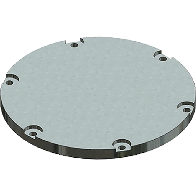
Image disclaimer: For identification and illustration only. It may show a product by another manufacturer and may not depict the exact item described; it is not a statement of any product’s quality, approval or performance. Third-party image and trademark rights belong to their owners. See full notice.
What Is It?
A Cover Plate (also known as a lid, access cover, or closure plate) is a flat, rigid plate that is bolted or secured over the opening of a base can, junction box, or other below‑grade AGL enclosure. Its primary purpose is to seal the enclosure, preventing water, de‑icing fluids, debris, and contaminants from entering and damaging the isolating transformer, cable connections, or other internal components. At the same time, it provides a flush surface designed for the same traffic loading as the base can it covers — the cover's load rating must match its can's class, since a light-duty L-867 cover is not rated for aircraft traffic even where a heavier L-868 installation nearby is.
Key characteristics of cover plates include:
- Flush Design: The plate is designed to sit flush with or slightly below the surrounding pavement surface, minimising the risk of damage from snowploughs or aircraft tyres.
- Watertight Seal: A neoprene or silicone gasket is fitted between the plate and the enclosure flange to provide a watertight seal, preventing moisture ingress.
- Load‑Bearing Capacity: Made from high‑strength steel or aluminium, the plate is designed to withstand heavy aircraft wheel loads (rated ≥50–100 kN vertical) without deformation or failure.
- Corrosion Protection: Hot‑dip galvanised, powder‑coated, or stainless steel construction ensures long‑term resistance to the harsh airfield environment.
Cover plates are used in the following applications:
- Base Cans: Sealing the top of base cans that do not have a fixture mounted directly on them (e.g., spare cans, junction points).
- Junction Boxes: Providing access to underground cable splices and terminations while protecting them from the environment.
- Distribution Boxes: Covering above‑ground or flush‑mounted distribution panels and enclosures.
- Earth Pits: Providing access to earthing connections while protecting them from debris and moisture.
- Test Points: Covering test access points for circuit testing and troubleshooting.
The cover plate is secured with bolts or a quick‑release mechanism, allowing for easy removal during maintenance. The plate is typically marked with the enclosure type or circuit identification for easy reference.
Purpose & Function
Any enclosure with no active fixture mounted on it — a spare base can, a junction box, an earth pit — is still an opening in the pavement, and an unsealed or poorly sealed opening is exactly as dangerous as a damaged fixture: it lets water and contaminants reach the electrical connections below, and it leaves a surface irregularity that aircraft wheels, snowploughs, or foreign object debris (FOD) can catch on. The cover plate's purpose is to give these unfixtured openings the same environmental sealing and load-bearing protection that an installed fixture would otherwise provide, restoring a flush, watertight, traffic-rated surface so that a maintenance access point or a cable splice never has to compromise on airfield safety just because there is no light or transformer sitting on top of it.
Where Is It Used?
Cover plates are used throughout the airfield wherever underground or below‑grade enclosures require a protective, flush‑mounted cover, including:
- Runway Lighting Circuits: Sealing base cans at junction points, spare cans, or locations where elevated fixtures are not installed.
- Taxiway Lighting Circuits: Covering junction boxes and base cans along taxiway lighting circuits.
- Approach Lighting Systems: Sealing base cans and junction boxes in approach lighting systems.
- Earth Pits and Earthing Systems: Providing access to earth pits while keeping them sealed and protected.
- Distribution and Control Panels: Covering flush‑mounted distribution boxes and control panels in the airfield.
- Test Points and Monitoring Points: Sealing test access points for circuit diagnostics and maintenance.
The plate is available in various diameters (150mm to 300mm) to match the base can or junction box size, and in thicknesses ranging from 10mm to 25mm depending on the load rating. The plate is typically recessed into the pavement so that the top surface is flush with the surrounding pavement, ensuring a smooth surface for vehicle and aircraft operations.
Installation & Location
The cover plate sits directly on the base can or junction box rim, set flush with the surrounding pavement or shoulder surface so it doesn't become a FOD or tripping hazard once installed. Fastener pattern and gasket seating are checked during fitting so the cover seals against water ingress into the empty or spare can beneath it; where the plate covers a spare (currently unused) can, its position and load rating are still set to the same pavement-load standard as an active fixture location, since the surface must handle the same aircraft or vehicle traffic regardless of what's installed beneath it.
How Does It Work?
The cover plate functions as a protective barrier and access point for below‑grade AGL enclosures. Its design ensures that the enclosure remains sealed and protected while providing a safe, level surface for pavement operations:
- Sealing: The plate is bolted onto the enclosure flange with a gasket between the two surfaces. When the bolts are torqued, the gasket is compressed, creating a watertight seal that prevents moisture, de‑icing fluids, and debris from entering the enclosure.
- Load Distribution: The plate distributes the load from aircraft, vehicles, and snowploughs over the full area of the enclosure flange, preventing localised stress and damage to the enclosure.
- Accessibility: The plate is secured with bolts that can be easily removed, allowing maintenance personnel to access the enclosure for inspection, testing, or repair of the internal components.
- Safety: The flush‑mounted design eliminates trip hazards and reduces the risk of tyre damage from protruding edges.
The installation process typically involves:
- Cleaning: The enclosure flange and the underside of the cover plate are cleaned to ensure a good seal.
- Gasket Placement: A gasket is placed on the enclosure flange, aligning with the bolt holes.
- Plate Placement: The cover plate is positioned over the enclosure, and the bolts are inserted.
- Torquing: The bolts are torqued to the specified value in a cross‑pattern to ensure even compression of the gasket.
- Level Check: The plate is checked to ensure it is level and flush with the surrounding pavement. If necessary, shims are used to achieve the correct height.
The cover plate is designed to provide a service life of 20+ years, with regular inspection of the gasket, bolts, and plate condition. The plate should be checked for corrosion, and the bolts should be re‑torqued periodically to maintain the seal.
System Architecture & Control Logic
The cover plate carries no electronic function — it is the load-bearing, sealed access point sitting directly above a below-grade enclosure such as a base can or junction box. Its role in the architecture is to let that enclosure remain buried and protected while still being reachable for maintenance, and to do so without becoming a hazard or an obstruction to the aircraft and vehicle traffic passing over it. It is rated for the traffic load of its specific location (a taxiway cover plate and an apron cover plate can have different load ratings) and sealed against surface water intrusion, but it has no status the ALCMS can see — its condition is confirmed the same way as the enclosure beneath it, by opening it during inspection.
Rated for the traffic load of its specific location — its condition is checked by opening it, not by any ALCMS signal.
Installation & Sealing Sequence
Physical Construction
The cover plate is a flat, load-rated disc of structural steel, stainless steel, or aluminium, sized to span and seal the open top of a base can or junction box while its perimeter bolt pattern matches the can's mounting flange. A continuous gasket, typically neoprene, EPDM, or silicone, is compressed between the plate and the can rim as the bolts are torqued down, forming the seal that gives the assembly its IP67/IP68 rating against water and dust ingress at the pavement surface. Plate thickness is selected to suit the expected aircraft wheel loading, with heavier-gauge plates or additional stiffening ribs used where higher load ratings are required. Surface finishing, hot-dip galvanising, powder-coating, or a plain/polished stainless finish, protects the plate from de-icing fluid and fuel exposure, and cable or conduit pass-through holes, where fitted, are individually sealed with grommets or glands to preserve the overall ingress protection.
Technical Parameters
| Parameter | Typical Value |
|---|---|
| Material | Structural steel (S235JR or S355JR), hot‑dip galvanised (min 85µm) or stainless steel (316L); also available in aluminium |
| Diameter | 150mm to 300mm (6" to 12") – matches base can or junction box size |
| Thickness | 10mm to 25mm (depending on load rating) |
| Surface Finish | Hot‑dip galvanised, powder‑coated, or stainless steel (plain or polished) |
| Gasket Material | Neoprene, EPDM, or silicone (oil‑ and fuel‑resistant) |
| Bolt Size | M10 to M16 (depending on plate size and load) |
| Load Capacity (vertical) | Matches its base can's class — light vehicular only for L-867 covers; ≥ 50 kN to 100 kN, aircraft-rated, for L-868 covers |
| IP Rating (with gasket) | IP67 / IP68 (submersible when properly sealed) |
| Corrosion Resistance | ≥ 500 hours salt spray (galvanised); ≥ 1000 hours (stainless) |
| Operating Temperature | -40°C to +85°C |
| Standards | FAA AC 150/5345‑42, ICAO Annex 14, EN 10025, ASTM A123 |
Applicable Standards
FAA AC 150/5345‑42
Specification for Airport Light Bases, Transformer Housings, Junction Boxes, and Accessories (includes cover plates)
ICAO Annex 14
Physical characteristics of AGL enclosures and covers
EN 10025
Hot‑rolled products of structural steels (material specification)
ASTM A123
Standard specification for zinc (hot‑dip galvanised) coatings on iron and steel products
Installation Requirements
Rim Condition Check
CivilConfirm the base can or junction box rim is clean, undamaged, and level before setting the plate, since a distorted rim prevents a flush, sealed fit.
Fastener Pattern & Gasket Seating
MechanicalCheck the fastener pattern and gasket seat evenly around the full perimeter before final torque, so the seal is continuous rather than only tight at a few points.
Load Rating Verification
CivilConfirm the plate's load rating matches the pavement classification of its location, whether it covers an active fixture or a spare can.
Flush-Fit & Level Setting
CivilSet the plate flush with the surrounding pavement or shoulder surface to avoid creating a FOD or tripping hazard.
Spare Can Position Recording
DocumentationWhere the plate covers a spare, currently unused can, record its position and load rating in the as-built record for future fixture installation.
Pre-Backfill Sign-off
DocumentationRecord rim condition, fastener torque, and level check before the surrounding area is reinstated.
Testing & Commissioning
Gasket Seating Check
Pre-InstallationClean the enclosure flange and cover-plate underside and confirm the gasket seats evenly before the bolts are torqued.
Bolt Torque Verification
Final AcceptanceTorque all retaining bolts evenly in sequence to compress the gasket uniformly and achieve the rated seal.
Ingress Protection Verification
Final AcceptanceConfirm the sealed plate meets its rated IP67/IP68 class before the surrounding pavement is finally reinstated.
Flush-Fit & Level Check
Final AcceptanceVerify the plate sits flush with the surrounding pavement surface, eliminating trip hazards and tyre-damage risk from proud edges.
Load Rating Verification
Pre-InstallationConfirm the plate's thickness and material match the load rating required for the expected aircraft, vehicle, and snowplough traffic.
Access & Removability Check
Final AcceptanceConfirm bolts can be removed and refitted cleanly, so the plate provides genuine access for future inspection without damage.
Documentation & As-Built Sign-off
Final AcceptanceRecord plate size, gasket type, and torque/seal verification results in the commissioning dossier for handover.
Inspection & Maintenance
Gasket Seal Inspection
AnnualCheck the neoprene, EPDM, or silicone gasket for compression set, cracking, or fuel degradation that could break the IP67/IP68 seal against the base can.
Bolt Torque Verification
AnnualRe-torque mounting bolts to spec so the plate maintains its rated ≥50 kN vertical load capacity and even gasket compression.
Surface Corrosion Check
AnnualInspect the plate surface and edges for coating breakdown, pitting, or galvanising loss, especially on trafficked or de-icing-fluid-exposed pavement.
Load Rating / Deflection Check
AnnualLook for deformation, cracking, or excessive deflection under wheel or vehicle loading that could indicate the plate is undersized or fatigued.
Pavement Interface Inspection
AnnualCheck the surrounding pavement or turf for settlement, gaps, or debris accumulation that could compromise the flush fit and drainage around the plate.
Skid Resistance Check
AnnualVerify the plate's surface finish still provides adequate skid resistance for foot and vehicle traffic passing over it.
Fastener Condition Check
AnnualInspect bolt heads and recessed fasteners for stripping, corrosion, or loosening that could complicate future removal for base can access.
Standing Water Check
AnnualConfirm no water pools on or around the plate after rain, which can indicate a failed seal or blocked drainage beneath the fixture.
Common Field Issues
Gasket Deterioration
The gasket can degrade over time due to UV exposure, temperature cycling, and chemical attack from de‑icing fluids and fuels. A deteriorated gasket allows water and contaminants to enter the enclosure. Replace the gasket at regular intervals (typically every 5‑10 years) and inspect it during every maintenance visit.
Corrosion of Bolts and Plate
Bolts and the plate surface can corrode, especially in coastal or chemically aggressive environments. Use stainless steel hardware, apply anti‑seize compound, and regularly inspect for rust. Touch up damaged galvanising or powder coating.
Loose Bolts
Vibration from aircraft and thermal cycling can cause the bolts to loosen, compromising the seal and creating a trip hazard. Use lock washers, thread‑locking compound, and schedule regular bolt torque checks as part of the maintenance program.
Plate Misalignment or Protrusion
If the cover plate is not installed flush with the pavement, it can be struck by snowploughs or aircraft tyres, causing damage to the plate, the enclosure, or the tyre. Ensure the plate is properly recessed and level, and use shims if necessary.
Stripped Bolt Threads
Repeated removal and installation of the bolts can strip the threads in the enclosure flange. Use thread inserts (Heli‑coils) to repair damaged threads, and apply anti‑seize compound to prevent galling.
Debris Accumulation Around Plate
Dirt, rubber deposits, and debris can accumulate around the edge of the cover plate, making it difficult to remove and potentially affecting the seal. Regularly clean the area around the plate and ensure the edge clearance is maintained.
Incorrect Gasket Compression
Over‑torquing or under‑torquing the bolts can result in incorrect gasket compression, leading to leaks or damage to the gasket. Always use a torque wrench and follow the manufacturer's specified torque values.
Troubleshooting Guide
Water or Contaminants Found Inside the Enclosure
Rust or Corrosion Found on Bolts or Plate Surface
Cover Plate Loose or Seal Compromised
Plate Struck by Snowplough, Vehicle, or Aircraft Tyre
Bolts Will Not Tighten Securely
Plate Difficult to Remove During Maintenance
Leak or Gasket Damage Despite a New Gasket Being Fitted
Failure Modes & Root Causes
Gasket Failure
Bolt or Plate Corrosion
Fastener Loosening from Vibration
Impact Damage from Ground Traffic
Stripped Enclosure Threads
Safety & Operational Notes
Assume the Enclosure Below Is Live
Electrical SafetyTreat the base can or junction box beneath the plate as energised until the associated series circuit has been de-energised, locked out, and verified zero energy at the CCR, even if the plate itself carries no current.
Manual Handling
Personnel SafetyCover plates are load-rated for aircraft and vehicle traffic and can be heavy for their size; use correct lifting technique or a lifting tool where provided, and avoid working alone on larger plates.
Airside Work Coordination
OperationalRemoving a cover plate creates an open enclosure and a surface irregularity on or near the movement area; coordinate with ATC and raise a NOTAM where the location falls within the runway or taxiway strip, and never leave a plate removed and unattended.
FOD Control
OperationalKeep fasteners, gaskets, and the plate itself accounted for at all times once lifted, and never leave a cover plate or its hardware loose on the pavement, since a dropped fastener or plate is a direct FOD hazard to aircraft.
Flush Fit on Reinstatement
ComplianceReinstate the plate flush with, or slightly below, the surrounding pavement or shoulder surface and torque fasteners evenly so the surface doesn't become a tripping or FOD hazard, regardless of whether the can beneath is active or spare.
Restore to Compliant State
ComplianceConfirm the gasket seats correctly and the plate sits flush before closing out the work, since a poorly reinstated plate allows water ingress into the enclosure below even if it looks secured.
Engineering & Expert Notes
Corroded Fasteners Complicate Future Access
MaintenanceGalvanic or salt-driven corrosion can seize cover plate bolts over time, risking stripped heads on the next access attempt; use an anti-seize compound compatible with the plate and fastener materials at every reinstall, not just when corrosion is already visible.
Inspect the Seal Separately From the Plate Itself
DurabilityA cover plate can look structurally sound while its gasket has degraded from repeated freeze-thaw cycling or de-icing fluid exposure, allowing water ingress the plate appears to be preventing; check gasket condition as its own line item rather than inferring it from the plate's visual state.
Re-Verify Load Rating After Any Visible Repair
ComplianceA cover plate that has been welded or otherwise repaired after cracking needs its load capacity re-verified before it goes back into a trafficked area; a visually sound repair is not the same as a confirmed load-rated one.
Confirm Electrical Continuity, Not Just Mechanical Seating
ElectricalWhere a cover plate forms part of the bonding path for an enclosure near powered equipment, a plate that seats and seals correctly can still fail to maintain electrical continuity; verify bonding continuity across the plate to the enclosure, especially after any repaint or corrosion treatment.
Track Anti-Skid Surface Wear Separately From Structural Condition
InspectionRepeated snowplough and vehicle traffic wears the anti-skid surface texture faster than it degrades the underlying plate structure; inspect surface texture on its own rather than assuming a structurally sound plate still provides adequate traction.
Verify Replacement Plates Match the Original Specification
ComplianceIn field emergencies it's common for a mismatched or generic plate to go in as a temporary fix and then stay in place; check part number and load rating against the original specification during any post-repair audit rather than assuming an installed plate is the correct one.
Frequently Asked Questions
Short answers about AGL cover plates: function, materials, load rating, standards and maintenance.
Q1What is a cover plate in airfield ground lighting?
A cover plate, also called a lid or access cover, is a flat rigid plate bolted over the opening of a base can, junction box or other below-grade AGL enclosure to seal it and give a flush, load-bearing surface.
Q2Where are cover plates used?
On base cans, spare cans and junction boxes in runway, taxiway and approach lighting circuits, on earth pits, and on flush-mounted distribution and control boxes.
Q3How does a cover plate keep an enclosure watertight?
It is bolted to the enclosure flange with a gasket between the surfaces. Torquing the bolts compresses the gasket, giving an IP67/IP68 seal against moisture, de-icing fluids and debris.
Q4What materials and sizes are cover plates made from?
Typically structural steel (S235JR or S355JR), hot-dip galvanised to at least 85 µm, or 316L stainless steel, in diameters from 150 mm to 300 mm and thicknesses of 10 mm to 25 mm depending on load rating.
Q5What load can a cover plate carry?
It must match its base can's class. The page gives light vehicular loading only for L-867 covers and at least 50 kN to 100 kN for aircraft-rated covers, so check the rating against the location.
Q6Which standards apply to cover plates?
The main references are FAA AC 150/5345-42 (light bases, transformer housings, junction boxes and accessories), ICAO Annex 14, EN 10025 for the steel and ASTM A123 for galvanising.
Q7How often should cover plates be inspected?
Annually. Check the gasket for compression set or fuel damage, re-torque the bolts and inspect the surface and edges for coating breakdown or corrosion.
Q8What are the common problems with cover plates?
Gasket deterioration, corroded bolts and plate, loose bolts from vibration, a plate that sits proud of the pavement and can be struck by snowploughs, and stripped bolt threads from repeated removal.
Related Components
Go Beyond the Component. Understand the Complete AGL System.
You have explored the component. Now understand how it works within the complete Airfield Ground Lighting system.
Learn AGL from fundamentals to design, installation, testing, photometry, commissioning, maintenance and troubleshooting through structured technical training at Precision AGL Academy.
Build practical knowledge. Understand the circuit. Read the standards. Troubleshoot with confidence.
Your next step in AGL starts here.
Need expert guidance on cover plate selection and installation for your AGL project?
Precision AGL Academy provides advice on material selection, gasket sealing, load ratings, and proper bolting techniques for reliable enclosure protection.
Follow the Academy
Important Notice, Disclaimer & Limitation of Liability
Please read before relying on any content on this page.
- Purpose and intended users. This page on Cover Plate is an independent educational and informational reference for competent, suitably trained and authorised airfield ground lighting (AGL) and aerodrome electrical personnel. It is not professional engineering, legal or regulatory advice, and using it does not create any professional or client relationship.
- Safety. Work on series circuits, constant current regulators (CCRs), isolating transformers, cables, connectors and lighting equipment can be fatal. Always apply the aerodrome’s permit-to-work and isolation/LOTO procedures, prove dead, use correctly rated instruments and PPE, and follow the manufacturer’s instructions. Nothing here authorises work on live equipment or the bypassing of any safety device or interlock.
- Aviation operations. Nothing here authorises installation, modification, energisation, adjustment, return to service, a change of operating category (CAT I/II/III), a NOTAM or any aerodrome certification or approval decision. These rest with the aerodrome operator, the air navigation service provider and the competent regulator.
- Specifications, ratings and typical values. Descriptions, parameters, ratings, dimensions, photometric values, wattages, service lives, maintenance tasks and intervals, failure modes, certifications (for example CE, FCC, UL or IEC marks) and part or type designations are general, typical and indicative. They may not match any particular product, make, model or version, and they are not a datasheet, design, specification, selection, sizing, procurement or acceptance criterion. The manufacturer’s current documents, the approved design and the project specification prevail.
- Standards and regulations. References to ICAO, FAA, IEC, IEEE, ISO, BIS, DGCA and other standards are paraphrased summaries for orientation only. They may be incomplete or out of date, and standards are revised from time to time. Consult the current official editions. Following this content does not guarantee compliance with any law, standard or regulatory approval, and the regulator’s requirements always prevail.
- No warranty. Content is provided “as is” and “as available”, without warranty of any kind, express or implied, including accuracy, completeness, currency or fitness for a particular purpose. Real installations differ in design, equipment make and model, age and condition.
- Limitation of liability. To the fullest extent permitted by applicable law, Precision AGL Academy, Precision AGL Solutions and their owners, authors and contributors are not liable for any injury, death, loss, damage, downtime, penalty or regulatory consequence, whether direct or indirect, arising from the use of, reliance on, or inability to use this content. Nothing in this notice excludes or limits any liability that cannot lawfully be excluded or limited.
- Independence, brands and no endorsement. This is an independent publication. It is not affiliated with, sponsored by or endorsed by ICAO, the FAA, the IEC, DGCA, AAI, any airport, regulator, supplier or equipment manufacturer. Third-party names, product designations, standard designations and trademarks (including Megger®, Siemens, Eaton, Crouse-Hinds, ADB SAFEGATE, Fluke, ABB and Honeywell) belong to their respective owners and are used only for identification and description. Mention of a brand, product or supplier is not a recommendation, and we do not sell, supply or quote for any component described.
- Images and third-party content. Images and illustrations are shown to help identify the type of component. They may show products of various manufacturers, may not depict the exact item described, and are not a statement about any product’s quality, approval or performance. Copyright and trademarks in third-party images, logos and photographs belong to their respective owners and are not claimed as ours. If you are a rights holder and want an image removed, replaced or credited, email precisionaglsolutions@gmail.com with the page address and we will act promptly.
- Training and services. Mentions of training, courses, consultation, advice, selection, installation, calibration or other support, including the “Learn…Certify” pathway, describe learning stages and are not an offer, quotation, tender or promise of any result. Contacting us or our replying creates no engagement or duty of care; an engagement exists only under a written agreement. We are not a regulator or certification body, and completing any course or reading this content is not a certification, accreditation or authorisation to work on any aerodrome.
- Copyright, privacy and corrections. © 2026 Precision AGL Academy. All rights reserved. Text, structure, compilations and diagrams may be viewed for personal reference and internal training only; any other copying, republication or commercial use needs our written permission. If you email, telephone or message us, we use your details only to respond and handle your matter, in line with applicable Indian law including the Digital Personal Data Protection Act, 2023; please do not send confidential or security-sensitive information. To display this page your browser requests fonts, icons and images from third-party servers, which receive your IP address and browser details under their own policies. Content is reviewed periodically with no obligation to update. To report an error, safety concern or rights issue, write to precisionaglsolutions@gmail.com.