Earth Tester
A specialized instrument used to measure the resistance of grounding systems and earth electrodes in AGL installations. Also known as an earth resistance tester or ground resistance meter, this tool verifies that earthing systems provide a low-resistance path to ground — essential for lightning protection, equipment safety, and proper operation of sensitive electronic systems.
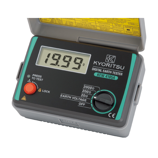
Image disclaimer: For identification and illustration only. It may show a product by another manufacturer and may not depict the exact item described; it is not a statement of any product’s quality, approval or performance. Third-party image and trademark rights belong to their owners. See full notice.
What Is It?
An Earth Tester (also known as a ground resistance tester or earth resistance meter) is a specialized instrument designed to measure the resistance of an electrical grounding system to earth. In AGL applications, it is used to verify that:
- Earthing systems provide a low-resistance path to ground for fault currents and lightning strikes.
- Earth electrodes (rods, plates, or grids) are properly installed and maintained.
- Equipment grounding meets safety standards and provides adequate protection.
- Lightning protection systems have sufficient conductivity to safely dissipate strike energy.
- Earth resistance remains within acceptable limits over time despite corrosion or soil changes.
Earth testers typically use the three-terminal (or four-terminal) fall-of-potential method or the clamp-on (stakeless) method. They are essential for commissioning new AGL installations, performing periodic safety inspections, and troubleshooting earthing-related issues.
Purpose & Function
The earth tester exists because a grounding system that looks intact can still be electrically useless if the resistance to true earth has crept up over time from corrosion, soil drying, or a loosened connection — and that failure is invisible until it's needed, during a lightning strike or fault current event, when it's too late to fix. Its purpose is to catch that silent degradation before it matters, by giving technicians an actual resistance value to compare against acceptable limits rather than assuming a grounding system installed correctly years ago still performs the same way today.
This matters because earthing is what keeps a fault current or lightning strike from finding its way through equipment, cabling, or a person, rather than dissipating safely into the ground. Periodic testing turns that protection from an assumption into a verified fact, which is why it's a standard part of both commissioning new AGL installations and ongoing safety inspection cycles.
Where Is It Used?
Earth testers are used across all AGL infrastructure where grounding is critical:
- CCR Rooms and Equipment Shelters: Verifying that the main earthing system provides low resistance for equipment safety.
- Lightning Protection Systems: Testing earth electrodes for lightning rods and air terminals on structures.
- Distribution Panels: Ensuring that all metallic enclosures and equipment are properly grounded.
- Junction Boxes and Transformers: Verifying earthing of isolating transformers and cable screens.
- Lighting Fixtures: Checking the earthing of metallic fixture components.
- Underground Cable Networks: Testing earthing points along primary and secondary cable routes.
- Standalone Structures: Testing earthing at PAPI units, wind cones, beacons, and other standalone equipment.
Testing is performed during installation, as part of routine preventive maintenance, and after lightning strikes or electrical faults.
Storage & Handling
Earth stakes and test leads are cleaned of soil and moisture before being packed away, since dried mud left on a stake or clamp can corrode contacts and affect readings on the next test. Leads are coiled without sharp bends and stored in the case's dedicated reels or compartments, keeping the current and potential leads separated from each other to avoid tangling on the next setup. The instrument itself is kept dry and within its rated storage temperature range, with batteries removed for extended storage to prevent leakage into the meter's electronics. Given how central this tester is to safety verification, it's calibrated on the interval specified by the manufacturer and checked against a known reference before any campaign of commissioning or post-lightning-strike testing, rather than assumed accurate from a stored calibration certificate alone.
How Does It Work?
Earth testers operate using two primary methods. The most common is the three-terminal (or four-terminal) fall-of-potential method, which requires placing auxiliary test spikes (current and potential electrodes) into the ground at specific distances from the earth electrode under test. The tester injects a known current between the earth electrode and a remote current electrode, then measures the voltage drop between the earth electrode and a potential electrode placed at varying distances. The resistance is calculated using Ohm's Law (R = V/I). This method is highly accurate but requires driving test spikes into the ground.
The clamp-on (stakeless) method uses a clamp with two coils — one to inject a signal and one to measure the resulting current — and does not require auxiliary electrodes. It is faster and more convenient but requires that the earth electrode under test be part of a complete loop. Modern earth testers often offer both methods, along with data logging, Bluetooth connectivity, and auto-ranging capabilities.
System Architecture & Control Logic
The two methods use different physical set-ups but converge on the same internal architecture. In fall-of-potential mode, an internal AC signal generator (deliberately using a non-mains, often frequency-swept, test signal to reject 50/60 Hz interference) drives current out through the C1 terminal, through the earth electrode, and back via the remote current spike C2. A separate, high-impedance potential path measures the voltage between the electrode and the P1 spike, isolating this sense path from the current-carrying path so that spike and lead resistance don't corrupt the reading — the same four-terminal principle used in loop resistance testing. In clamp-on mode, the MCU instead drives an injection coil in the clamp and reads the induced current in a second sense coil around the same jaw, since there are no auxiliary spikes to connect. Either way, the front-end signal is synchronously demodulated (locked to the injected test frequency) before the ADC, which is what lets the instrument reject stray earth currents and 50 Hz mains pickup that would otherwise swamp a simple DC measurement. The MCU then computes R = V/I, and on multi-point tests, checks whether resistance has plateaued as spike distance increases to flag an invalid fall-of-potential curve before displaying a final value.
Two Measurement Methods
Physical Construction
The earth tester is housed in a rugged, weather-resistant polymer case sized for field use, with recessed, shrouded terminals for the earth electrode, current, and potential test leads to prevent accidental contact during live testing. Internally, the AC test-signal generator, synchronous detector, and battery pack sit on a shielded PCB assembly designed to reject mains-frequency interference picked up through the long test-lead runs used in fall-of-potential testing. A backlit LCD sits behind a protective window, and a sealed keypad or rotary selector switch provides splash-proof control input. The unit typically ships with a reel or spool of insulated test lead, a set of driven earth stakes, and a carrying case or harness sized to transport the extended leads and stakes needed to reach the 20–50m electrode spacing used in standard test setups.
Technical Parameters
| Parameter | Typical Value |
|---|---|
| Measurement Method | 3-pole (fall-of-potential), 4-pole, or clamp-on (stakeless) |
| Resistance Range | 0.01 Ω to 2000 Ω |
| Accuracy | ±2% of reading ± 2 counts (typical) |
| Test Voltage | 50V AC (or less, depending on model) |
| Test Frequency | 125 Hz (to avoid interference from mains) |
| Current Electrode Distance | Typically 20m to 50m from earth electrode |
| Potential Electrode Distance | Typically 62% of current electrode distance |
| Display | LCD with backlight, 3.5 to 4-digit |
| Data Storage | 100+ test records with time/date |
| Interface | USB or Bluetooth (optional) |
| Power Supply | Rechargeable battery or 6x AA batteries |
| Safety Rating | CAT III 300V / CAT IV 150V |
| Operating Temperature | -10°C to +50°C |
| Standards Compliance | IEC 61557-5, IEEE 81, BS 7430 |
Electrical Requirements
| Requirement | Typical Value |
|---|---|
| Circuit Type | Battery-powered handheld test instrument — not connected to mains or the airfield series circuit during use |
| Power Supply | Rechargeable battery pack or 6 x AA batteries |
| Test Output | 50V AC (or less) test signal at 125Hz, galvanically isolated from the battery supply |
| Cable Type | Test leads with insulated probes/stakes rated to the instrument's CAT rating |
| Safety Rating | CAT III 300V / CAT IV 150V input protection |
| Earthing/Grounding | The instrument itself is not earthed — it measures the resistance of the earth electrode under test |
| Fault Protection | Input overvoltage protection to the rated CAT level |
| Standards | IEC 61557-5 |
Applicable Standards
IEC 61557-5
Electrical safety in low voltage distribution systems – earth resistance test equipment
IEEE 81
Guide for measuring earth resistivity, ground impedance, and earth surface potentials
BS 7430
Code of practice for protective earthing of electrical installations
FAA AC 150/5340-26
Maintenance of Airport Visual Aid Facilities — includes grounding, bonding, and electrical safety guidance for AGL maintenance staff
Setup Requirements
Calibration Currency Check
Pre-UseConfirm the instrument's calibration certificate is current before relying on the readings.
Lead & Stake Condition Check
Pre-UseInspect leads, clamps, and stakes for corrosion or damaged insulation before use, since a dirty or corroded contact skews resistance readings.
Internal Test Resistor Check
Pre-UseVerify the instrument against its built-in test resistor before taking a field measurement.
Stake Spacing & Site Layout
Pre-UseLay out the potential and current stakes at the spacing the fall-of-potential method requires for the earth system under test.
Battery Check
Pre-UseVerify battery charge is sufficient for the planned test sequence before starting.
Testing & Commissioning
Calibration Certificate Verification
AcceptanceConfirm the tester's calibration certificate is current before it is issued for earthing system testing.
Internal Test Resistor Function Check
AcceptanceVerify the tester reads correctly against its internal or an external precision test resistor before field use.
Lead & Stake Continuity Check
AcceptanceInspect and continuity-test all test leads and driven earth stakes for damage or corrosion that could introduce measurement error.
Fall-of-Potential Function Check
AcceptancePerform a test measurement on a known test site or reference electrode array to confirm correct fall-of-potential operation before formal testing begins.
Documentation & Sign-off
AcceptanceLog the function-check results and calibration due date against the instrument's serial number.
Inspection & Maintenance
Calibration Check
AnnualSend the tester for calibration against a traceable resistance standard to confirm accuracy of earth resistance readings.
Test Lead & Electrode Inspection
QuarterlyCheck test leads, spikes, and electrode connections for corrosion or damage that could introduce measurement error.
Battery Check
QuarterlyVerify battery condition, particularly important for maintaining the 125 Hz test frequency used to filter stray voltage interference.
Functional Self-Test
Before each useTest against a known resistance or the unit's built-in check function before conducting fall-of-potential measurements.
Noise Indicator Verification
AnnualConfirm the noise/interference indicator function is operating correctly so stray voltage conditions are reliably flagged.
Common Field Issues
Stray Voltage Interference
Nearby energized cables or stray currents can affect earth resistance measurements, especially in industrial environments. Using a test frequency of 125 Hz (rather than 50/60 Hz) helps filter out interference. Some testers include a "noise" indicator to warn of high interference levels.
Improper Electrode Spacing
For the fall-of-potential method, incorrect spacing of the current and potential electrodes can lead to inaccurate readings. The potential electrode should be placed at 62% of the distance between the earth electrode and the current electrode for optimal accuracy.
Dry or Frozen Soil
Soil resistivity increases significantly in dry or frozen conditions, leading to higher earth resistance readings. Testing should be performed when soil conditions are representative of normal operating conditions, or moisture should be added to the electrode area to simulate worst-case scenarios.
Troubleshooting Guide
Unstable or Wildly Fluctuating Reading
Reading Doesn't Match Previous Test at Same Location
Tester Shows Open Circuit or No Reading
Failure Modes & Root Causes
Stray Voltage / Noise Pickup
Incorrect Electrode Placement
Test Lead or Spike Connection Fault
Safety & Operational Notes
Disconnect Bonding Before Testing
Electrical SafetyDisconnect the electrode or system under test from the rest of the earthing/bonding network before measuring, so the reading reflects that electrode alone and stray current from the wider system does not affect it or the tester.
Never Test on a Live or Recently-Struck System
Electrical SafetyDo not connect the tester to a system that may be carrying fault current, and avoid earth testing immediately after a lightning event until the site has been confirmed safe.
Locate Buried Services Before Placing Spikes
OperationalCheck for buried cables, pipes, or ducts before driving auxiliary test spikes into the ground, and keep spike placement clear of live cable routes.
PPE for Spike Driving
Personnel SafetyWear appropriate PPE (gloves, eye protection) when driving or removing test spikes, particularly in hard or stony ground.
Airside Coordination
OperationalCoordinate with ATC/airside operations before testing earthing systems within the movement area or its safety zones.
Verify Instrument Calibration
ComplianceConfirm the tester's calibration is current and check it against a known reference resistance periodically, since an out-of-calibration reading can mask a genuine high-resistance earth fault.
Reinstate Bonding After Testing
ComplianceReconnect and verify all bonding and earthing connections disturbed for the test before leaving the site, so the system is not left with a compromised fault path.
Engineering & Expert Notes
Trend Readings Across Seasons, Not Just Year-on-Year at the Same Time
TestingSoil moisture and temperature swing earth resistance readings significantly between wet and dry seasons; a single annual test taken at the same time each year can mask a genuinely degrading earth system if that reading happens to fall during a consistently favourable season. Logging readings across the year gives a far more reliable trend than one spot-check.
Auxiliary Electrode Spacing Affects Reading Accuracy More Than People Expect
TechniqueThe fall-of-potential method's accuracy depends heavily on placing the auxiliary test electrodes far enough apart and outside the resistance area of the electrode under test; cramped spacing due to limited space on an airfield can produce a misleadingly low or unstable reading even with a perfectly functioning instrument.
Test Individual Electrodes Before Assuming a Grid Reading Reflects Every Rod
DiagnosticsA combined earthing grid or ring can measure well overall while one individual electrode within it has failed or corroded almost completely, its poor performance masked by the parallel paths from healthy electrodes nearby; where a grid reading looks marginal, testing individual electrode contributions helps find which one actually needs attention.
Stray Currents Near Active Equipment Can Distort Readings
Field PracticeTesting near energised equipment, buried cabling, or other earthing systems can introduce stray currents that bias an earth resistance reading; where possible, de-energise nearby circuits during testing or use an instrument and technique designed to reject interference, and treat a suspiciously unstable reading as a possible interference symptom rather than a genuine fault.
Corroded Electrode Connections Fail Silently Between Tests
DurabilityA test lead connection or bonding point can corrode to high resistance without any visible external sign, skewing the reading independently of the electrode's actual condition in the ground; inspect and clean physical connection points at every test rather than relying on the meter reading alone to judge overall system health.
Calibrate the Tester Itself, Not Just the System It's Testing
CalibrationAn earth tester carried in a field kit sees rough handling and can drift out of calibration without any obvious symptom on the display; verify it against a known resistance standard on the same interval as other precision test equipment rather than assuming it's accurate simply because it still produces a plausible-looking reading.
Frequently Asked Questions
Short answers about earth testers in AGL maintenance: what they measure, methods, accuracy, standards, calibration and common faults.
Q1What is an earth tester?
An earth tester, also called a ground resistance tester or earth resistance meter, measures the resistance of an electrical grounding system to earth. It verifies that earthing and lightning protection systems give a low-resistance path for fault currents and lightning strikes.
Q2Why test earth resistance?
A grounding system that looks intact can still be electrically useless if resistance has crept up from corrosion, soil drying or a loose connection. That failure is invisible until a lightning strike or fault, so testing catches the silent degradation before it matters.
Q3Where is an earth tester used in AGL?
CCR rooms and equipment shelters, lightning protection earth electrodes, distribution panels, junction boxes and transformers, lighting fixtures and underground cable networks.
Q4How does an earth tester measure resistance?
Mainly by the fall-of-potential method. It injects a known current between the electrode under test and a remote current electrode, measures the voltage drop to a potential electrode, and calculates R = V/I. Clamp-on (stakeless) testers are also available.
Q5How far apart should the test spikes be placed?
The current electrode is typically 20–50 m from the earth electrode, and the potential electrode at about 62% of the current electrode distance. Incorrect spacing is a common cause of readings that don't match previous tests.
Q6What are the typical specifications?
Resistance range of 0.01–2,000 Ω, accuracy of ±2% of reading ± 2 counts, a 125 Hz test frequency at 50 V AC or less, battery power and a CAT III 300 V / CAT IV 150 V safety rating.
Q7Why does an earth tester use 125 Hz?
It avoids interference from mains frequency, which helps filter stray voltage from nearby energised cables. Some testers also have a noise indicator, and a reading should not be accepted while it is active.
Q8Which standards apply to earth testers?
The main references are IEC 61557-5 (earth resistance test equipment), IEEE 81 (measuring earth resistivity and ground impedance), BS 7430 (protective earthing) and FAA AC 150/5340-26 (maintenance of airport visual aid facilities). Always verify the current edition and your approved requirements.
Q9How often should an earth tester be calibrated and checked?
Typical intervals are before each use for a functional self-test, quarterly for test lead and electrode inspection and battery checks, and annually for calibration against a traceable resistance standard and noise indicator verification. Your approved maintenance programme takes precedence.
Q10Why is my earth resistance reading unstable?
Stray voltage from nearby energised cables or buried power circuits is being picked up by the test leads. Check the noise indicator, use 125 Hz, move the spikes further from live cabling and retest.
Q11Why doesn't a reading match the previous test at the same location?
Incorrect electrode spacing or placement, or changed soil conditions such as dry, frozen or waterlogged ground. Re-check spacing and record soil conditions with each test.
Related Components
Go Beyond the Component. Understand the Complete AGL System.
You have explored the component. Now understand how it works within the complete Airfield Ground Lighting system.
Learn AGL from fundamentals to design, installation, testing, photometry, commissioning, maintenance and troubleshooting through structured technical training at Precision AGL Academy.
Build practical knowledge. Understand the circuit. Read the standards. Troubleshoot with confidence.
Your next step in AGL starts here.
Need expert guidance on earth tester selection or interpreting earth resistance measurements for your AGL system?
Precision AGL Academy provides advice on tester selection, measurement methods, and ensuring compliant earthing systems.
Follow the Academy
Important Notice, Disclaimer & Limitation of Liability
Please read before relying on any content on this page.
- Purpose and intended users. This page on Earth Tester is an independent educational and informational reference for competent, suitably trained and authorised airfield ground lighting (AGL) and aerodrome electrical personnel. It is not professional engineering, legal or regulatory advice, and using it does not create any professional or client relationship.
- Safety. Work on series circuits, constant current regulators (CCRs), isolating transformers, cables, connectors and lighting equipment can be fatal. Always apply the aerodrome’s permit-to-work and isolation/LOTO procedures, prove dead, use correctly rated instruments and PPE, and follow the manufacturer’s instructions. Nothing here authorises work on live equipment or the bypassing of any safety device or interlock.
- Aviation operations. Nothing here authorises installation, modification, energisation, adjustment, return to service, a change of operating category (CAT I/II/III), a NOTAM or any aerodrome certification or approval decision. These rest with the aerodrome operator, the air navigation service provider and the competent regulator.
- Specifications, ratings and typical values. Descriptions, parameters, ratings, dimensions, photometric values, wattages, service lives, maintenance tasks and intervals, failure modes, certifications (for example CE, FCC, UL or IEC marks) and part or type designations are general, typical and indicative. They may not match any particular product, make, model or version, and they are not a datasheet, design, specification, selection, sizing, procurement or acceptance criterion. The manufacturer’s current documents, the approved design and the project specification prevail.
- Standards and regulations. References to ICAO, FAA, IEC, IEEE, ISO, BIS, DGCA and other standards are paraphrased summaries for orientation only. They may be incomplete or out of date, and standards are revised from time to time. Consult the current official editions. Following this content does not guarantee compliance with any law, standard or regulatory approval, and the regulator’s requirements always prevail.
- No warranty. Content is provided “as is” and “as available”, without warranty of any kind, express or implied, including accuracy, completeness, currency or fitness for a particular purpose. Real installations differ in design, equipment make and model, age and condition.
- Limitation of liability. To the fullest extent permitted by applicable law, Precision AGL Academy, Precision AGL Solutions and their owners, authors and contributors are not liable for any injury, death, loss, damage, downtime, penalty or regulatory consequence, whether direct or indirect, arising from the use of, reliance on, or inability to use this content. Nothing in this notice excludes or limits any liability that cannot lawfully be excluded or limited.
- Independence, brands and no endorsement. This is an independent publication. It is not affiliated with, sponsored by or endorsed by ICAO, the FAA, the IEC, DGCA, AAI, any airport, regulator, supplier or equipment manufacturer. Third-party names, product designations, standard designations and trademarks (including Megger®, Siemens, Eaton, Crouse-Hinds, ADB SAFEGATE, Fluke, ABB and Honeywell) belong to their respective owners and are used only for identification and description. Mention of a brand, product or supplier is not a recommendation, and we do not sell, supply or quote for any component described.
- Images and third-party content. Images and illustrations are shown to help identify the type of component. They may show products of various manufacturers, may not depict the exact item described, and are not a statement about any product’s quality, approval or performance. Copyright and trademarks in third-party images, logos and photographs belong to their respective owners and are not claimed as ours. If you are a rights holder and want an image removed, replaced or credited, email precisionaglsolutions@gmail.com with the page address and we will act promptly.
- Training and services. Mentions of training, courses, consultation, advice, selection, installation, calibration or other support, including the “Learn…Certify” pathway, describe learning stages and are not an offer, quotation, tender or promise of any result. Contacting us or our replying creates no engagement or duty of care; an engagement exists only under a written agreement. We are not a regulator or certification body, and completing any course or reading this content is not a certification, accreditation or authorisation to work on any aerodrome.
- Copyright, privacy and corrections. © 2026 Precision AGL Academy. All rights reserved. Text, structure, compilations and diagrams may be viewed for personal reference and internal training only; any other copying, republication or commercial use needs our written permission. If you email, telephone or message us, we use your details only to respond and handle your matter, in line with applicable Indian law including the Digital Personal Data Protection Act, 2023; please do not send confidential or security-sensitive information. To display this page your browser requests fonts, icons and images from third-party servers, which receive your IP address and browser details under their own policies. Content is reviewed periodically with no obligation to update. To report an error, safety concern or rights issue, write to precisionaglsolutions@gmail.com.