Externally Illuminated Windsock
A fabric wind cone illuminated by external floodlights positioned around the mast, providing clear visibility of wind direction and speed at night. This design allows for easy maintenance, lamp replacement without mast disassembly, and the use of standard light fixtures.
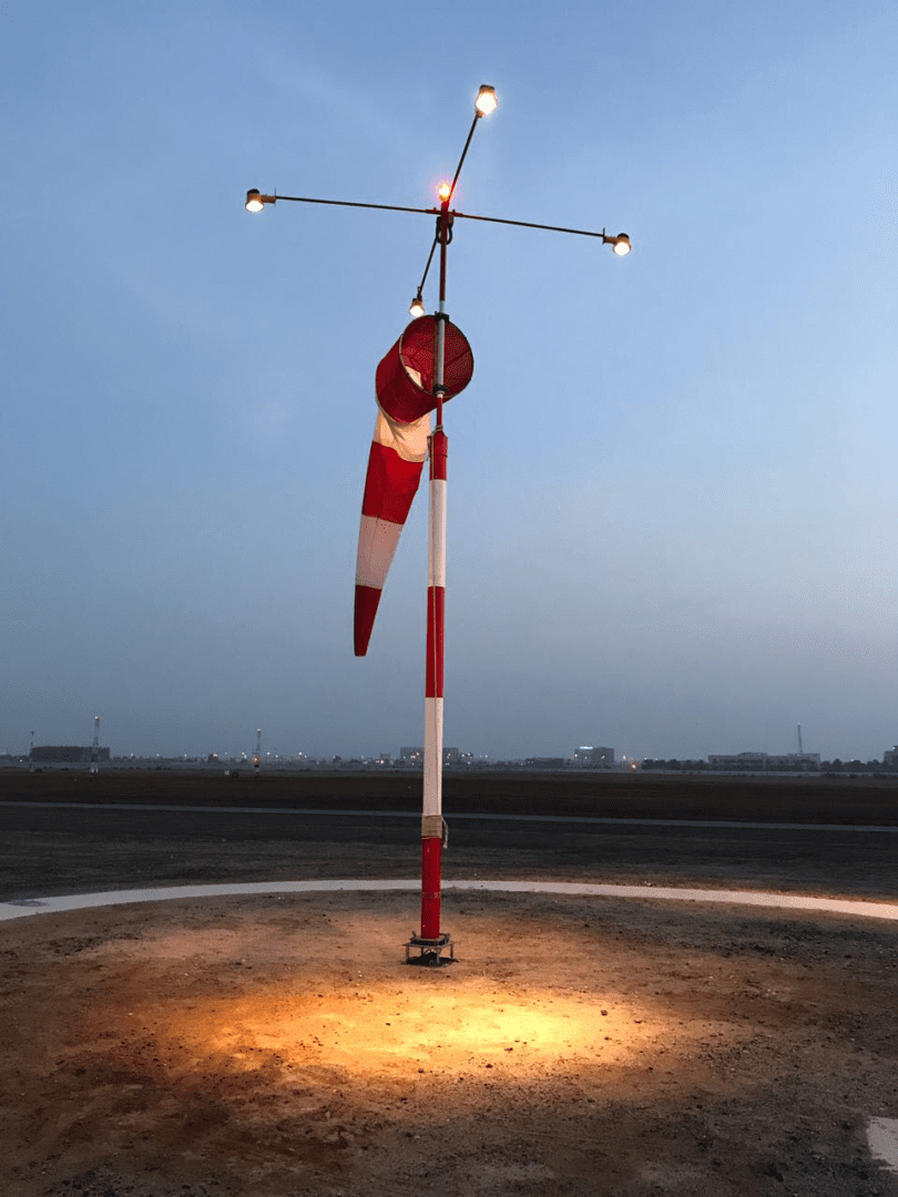
Image disclaimer: For identification and illustration only. It may show a product by another manufacturer and may not depict the exact item described; it is not a statement of any product’s quality, approval or performance. Third-party image and trademark rights belong to their owners. See full notice.
What Is It?
An Externally Illuminated Windsock is a wind cone assembly that uses external floodlights or spotlights mounted on the mast or nearby structures to illuminate the windsock from the outside. This is the traditional and most common method of windsock illumination. The light sources are typically LED or halogen floodlights positioned at the base of the mast or on separate poles, aimed upward to bathe the entire windsock in light. This design offers several advantages: easy lamp replacement (no need to enter the mast), the ability to use standard, off‑the‑shelf lighting fixtures, and the flexibility to adjust the beam angle and intensity to suit different wind cone sizes and locations. External illumination is also easier to inspect and maintain, as all lighting components are accessible at ground level or on the mast's exterior.
Purpose & Function
External illumination exists to keep a windsock visible at night using simple, easily maintained equipment: because the light source sits outside the mast, technicians can inspect, adjust, or replace it from ground level without accessing the interior of the structure, which keeps maintenance straightforward and downtime short if a lamp fails. This practicality is a real safety consideration in its own right, since a windsock that goes dark at night because of a hard-to-service internal fault loses its value exactly when pilots most need a wind reference.
The flexibility to adjust beam angle and intensity also lets the lighting be matched to windsock size and site conditions, ensuring the sock stays clearly readable from the air or the runway threshold, which is the entire purpose of illuminating it in the first place.
Where Is It Used?
Used at a wide range of airfields, heliports, and military installations where windsock illumination is required. Particularly common at larger airports, military airbases, and facilities where maintenance access is a priority. The external illumination design is also preferred in environments where the windsock mast is too small to accommodate internal lighting, or where existing floodlight infrastructure can be repurposed. It is also used at temporary and remote airfields where simplicity and ease of maintenance are critical.
Installation & Location
Floodlights are mounted on a ground-level pole or bracket set back from the base of the windsock mast, angled upward so the beam washes the full length of the sock without glaring toward an approaching aircraft. Fixture spacing and aiming are set during commissioning so the sock remains evenly lit from tail to throat regardless of wind direction, since the sock itself rotates freely on the mast head. Power cabling runs underground in duct from the floodlight bases back to the local distribution point, with the fixtures wired on their own circuit (often via a photocell or timer) so illumination can be verified and maintained independently of the mast structure itself. Because the light source sits at ground level, the mounting position is also chosen for straightforward access, so lamp replacement and aiming checks can be carried out without climbing the mast.
How Does It Work?
The externally illuminated windsock uses one or more floodlights mounted on the mast or on separate poles. The floodlights are typically positioned at the base of the mast, aimed upward to illuminate the full length of the wind cone. Some installations use multiple floodlights arranged around the mast to ensure even illumination from all sides. The light source is usually a high‑intensity LED floodlight with a wide beam angle (60°–120°) to cover the entire windsock. A photocell or timer controls the on/off cycle. The floodlights are housed in weatherproof enclosures (IP66/IP67) with corrosion‑resistant materials. The windsock itself is made from opaque, UV‑resistant fabric (orange and white bands) that reflects the external light, making it clearly visible at night. The external design allows for easy lamp replacement, cleaning, and adjustment of the light beam.
System Architecture & Control Logic
Unlike runway and taxiway edge lights, windsock floodlights are not part of the constant current series circuit — they are standard AC fixtures wired in parallel on their own dedicated lighting circuit, switched as a group by a photocell (or timer) rather than stepped through CCR current levels. This keeps the control logic simple by design: there is no intensity-step selection tied to visibility category, no series-loop fault monitoring, and no isolating transformer in the circuit, because the windsock is a wind-direction reference rather than a category-dependent visual aid. The photocell typically drives a contactor that energises the whole floodlight group at dusk and de-energises it at dawn, with a manual override at the local distribution point for maintenance or testing; where the site has an ALCMS, the circuit's on/off state is commonly wired back as a simple status point so a failed photocell or tripped breaker shows up as a fault, but the floodlights themselves remain outside the CCR-controlled visual aid system.
Illuminated From the Outside In
Opaque, UV-resistant orange/white fabric bounces the external beam back to the observer; nothing needs to be inside the mast.
Because every lighting component sits at the base of the mast or on nearby poles, lamp replacement and beam adjustment happen entirely at ground level — the trade-off against the Internally Illuminated Windsock is potential glare and less even coverage if the floodlights aren't carefully aimed.
Physical Construction
This configuration pairs a standard fabric wind cone assembly with one or more floodlight fixtures mounted separately from the cone itself, either on brackets fixed to the mast below the swivel point or on dedicated poles positioned around the base. The floodlight housings are weatherproof, corrosion-resistant enclosures rated to IP66/IP67, with a hardened glass or polycarbonate lens sealed against moisture and a mounting yoke that allows the beam angle to be adjusted so the full length of the cone is evenly lit without excessive spill or glare toward approaching aircraft. Because the light source sits outside the cone and mast, wiring runs from the floodlight housing down to a ground-level junction box are kept separate from the mast's internal cabling, simplifying lamp replacement and maintenance access without requiring work at height. The cone itself follows standard wind cone construction — UV-stabilised, flame-retardant polyester fabric on a ring-supported throat — while the mast is a conventional galvanized steel, aluminium, or fibreglass pole without the need for internal illumination wiring or a translucent fabric specification.
Technical Parameters
| Parameter | Typical Value |
|---|---|
| Light Source | LED floodlight (50–150 W) or halogen (150–300 W) |
| Luminous Output | 5,000–15,000 lumens per floodlight |
| Beam Angle | 60°–120° (wide flood) for even coverage |
| Number of Fixtures | 1–3 floodlights (depending on windsock size) |
| Cone Material | Opaque, UV‑stabilized polyester (flame‑retardant) |
| Cone Dimensions (ICAO) | Truncated cone at least 3.6 m long with a throat diameter of at least 0.9 m, proportioned so it extends fully in a wind of about 15 kt and indicates direction clearly at 6 kt |
| Siting (ICAO) | At least one indicator, visible from aircraft in flight and from the movement area, sited clear of turbulence from nearby buildings or terrain and marked by a circle 15 m in diameter where practicable |
| Night Illumination | At least one wind direction indicator must be illuminated at an aerodrome intended for use at night |
| Cone Colour | Orange and white bands (high visibility) |
| Floodlight Mounting | Mast‑mounted bracket or separate poles |
| Protection Class | IP66 / IP67 (weatherproof fixtures) |
| Power Supply | 230V AC or 24V DC (with converter) |
| Control | Photocell, timer, or manual switch |
Electrical Requirements
| Requirement | Typical Value |
|---|---|
| Circuit Type | Local mains branch circuit (230V AC) or low-voltage 24V DC via step-down converter; not part of the runway series (CCR) circuit |
| Cable Type | Standard weatherproof armoured mains cable, sized to the floodlight load |
| Circuit Protection | MCB and RCD (residual current device) at the local distribution point |
| Control Wiring | Photocell, astronomical timer, or manual switch wired into the lighting circuit |
| Floodlight Wiring | Separate cable run to each floodlight with weatherproof glanded entries |
| Earthing/Grounding | Floodlight fixtures, mast/poles, and enclosure bonded to site earth |
| Insulation Resistance | ≥ 1 MΩ (mains circuit megger test) |
| Standby/Backup | Optional battery backup or connection to airfield emergency supply for critical sites |
Photometric Requirements
| Parameter | Typical Value |
|---|---|
| Cone Surface Illuminance | ≥ 50 lux average on the cone surface, measured at the mid-point along its length |
| Minimum Point Illuminance | ≥ 20 lux (FAA AC 150/5345-27 minimum: 2 foot-candles/≈21.5 lux at throat, trailing end, and centre points, tested at 30° intervals through a full rotation) |
| Uniformity Ratio | Max/min illuminance ≤ 4:1 across the cone surface |
| Floodlight Aim Coverage | Beam pattern set to cover full cone length and 360° of rotation as the sock swings with wind |
| Colour Rendering | CRI ≥ 70, sufficient to distinguish orange and white bands at night |
| Spill/Glare Control | Floodlight aim and shielding limited to avoid glare towards approach/departure flight paths |
| Maintenance Factor | ≥ 50% of commissioned illuminance before floodlight cleaning/replacement is due |
| Test Method | Handheld illuminance meter at multiple points on the cone surface, or photometric van for critical sites |
Applicable Standards
ICAO Annex 14, Vol I — 5.1.1
Wind direction indicator: provision, location, cone dimensions and colour, and the requirement for illumination at an aerodrome intended for use at night
ICAO Doc 9157 Part 4
Aerodrome Design Manual, Visual Aids — wind direction indicator siting and marker circle guidance
FAA AC 150/5345-27
Specification for Wind Cone Assemblies — covers both externally lighted (Style I‑A) and internally lighted (Style I‑B) configurations, including the photometric test methods used at commissioning
Local electrical/building code
Governs the AC branch circuit, MCB/RCD protection, and earthing, since the floodlight circuit is a standard mains installation rather than the AGL constant-current series circuit
Note on figures: the values on this page are typical reference figures drawn from the standards listed above and from manufacturers’ published data. Requirements differ between ICAO, FAA and national regimes, and between aerodrome code numbers, approach categories and equipment types. Always design, install, commission and maintain to the project specification, the manufacturer’s manual and the standard in force at the aerodrome.
Installation Requirements
Mast Foundation & Frangible Coupling
CivilSet the mast foundation and, where the site falls within a frangibility-sensitive area, fit the breakaway coupling so the assembly yields safely on impact.
Floodlight Pole/Bracket Positioning
CivilPosition floodlight poles or brackets set back from the mast base at ground level, chosen for straightforward access to lamp replacement and aiming checks.
Cable Route to Distribution Point
ElectricalRun floodlight power cabling underground in duct from the fixture bases back to the local distribution point, on a circuit separate from the mast structure.
Photocell/Timer Control Wiring
ElectricalWire the floodlight circuit through its photocell, timer, or manual switch so illumination can be verified and maintained independently of the mast.
Swivel Bearing & Cone Fitting
MechanicalFit the cone and throat ring to the mast's swivel bearing so the assembly rotates freely into the wind without binding.
Floodlight Beam Aiming
MechanicalAim each floodlight so the beam washes the full length of the sock evenly from tail to throat, without glaring toward an approaching aircraft.
Siting & Obstacle Clearance Check
CivilConfirm the installation sits within the obstacle-limitation surface for the runway and clear of buildings, trees, or other turbulence-inducing obstructions.
Pre-Energisation Sign-off
DocumentationRecord mast position, cable route, and floodlight aiming as-built before the installation is accepted for commissioning.
Testing & Commissioning
Insulation Resistance Test
Pre-EnergisationMegger-test the floodlight circuit and supply cabling before the installation is energised, confirming insulation resistance clears the acceptable minimum.
Floodlight Circuit Continuity Test
Pre-EnergisationVerify continuity of the floodlight wiring end to end, ruling out open circuits or damaged connections before first energisation.
Photocell/Timer Function Test
EnergisationConfirm the photocell or timer switches the floodlights on at dusk and off at dawn, or override correctly if manually triggered.
Floodlight Beam Aim & Coverage Verification
Functional TestCheck each floodlight is aimed to illuminate the full length of the windsock evenly, with no dark bands or unlit sections.
Photometric Illumination Test
Final AcceptanceMeasure illumination levels on the windsock fabric with a calibrated light meter against ICAO/FAA commissioning tolerances.
Windsock Free-Rotation & Alignment Check
Functional TestConfirm the windsock rotates freely on its bearing and aligns correctly with wind direction without binding or drag.
Enclosure & Seal Check
Pre-EnergisationInspect floodlight housings and cable entries for intact seals, confirming the IP66/IP67 rating before the site is finally closed out.
Documentation & As-Built Sign-off
Final AcceptanceRecord insulation, continuity, and photometric readings alongside as-built position in the commissioning dossier for handover.
Inspection & Maintenance
Floodlight Function & Alignment Check
Semi-annualConfirm each floodlight still illuminates and remains aimed to give even coverage across the cone, since a misaligned fixture leaves shadowed or unlit sections.
Lens & Fixture Cleaning
QuarterlyClear dust, insect residue, and weathering film from floodlight lenses so luminous output stays within the 5,000–15,000 lumen spec.
Photocell / Timer Control Verification
Semi-annualTest the control method (photocell, timer, or manual switch) to confirm the floodlights activate and deactivate at the correct times.
Windsock Cone Condition Inspection
QuarterlyCheck the cone fabric for fading, tears, or fraying, since a degraded cone undermines both visibility and wind indication accuracy.
Swivel Bearing Lubrication & Function Check
Semi-annualLubricate the swivel bearing and confirm free 360° rotation, since a stiff bearing gives a false wind direction reading.
Seal & Weatherproofing Inspection
AnnualCheck floodlight housing seals and gaskets for cracking or degradation and confirm the IP66/IP67 rating is still intact.
Cable & Power Connection Inspection
AnnualExamine supply wiring and connectors for corrosion or loose terminations, a common cause of intermittent floodlight failure.
Mounting Bracket & Structural Check
AnnualInspect floodlight and mast mounting brackets for corrosion, loosening, or fatigue from wind loading.
Common Field Issues
Floodlight Misalignment
Floodlights can shift due to wind or vibration, causing uneven illumination or shadows on the windsock. Regular inspection and realignment of floodlights is necessary to maintain even coverage.
Lamp/LED Failure
External floodlights are exposed to the elements and can fail due to moisture ingress, electrical faults, or lamp burnout. Regular replacement and use of high‑quality fixtures with long‑life LEDs is recommended.
Light Pollution and Glare
External floodlights can cause glare for pilots on final approach if not properly shielded. Using directional floodlights with glare shields and careful positioning can mitigate this issue.
Troubleshooting Guide
Entire Windsock Goes Dark at Night
One or More Floodlights Dark, Others Working
Uneven Illumination or Shadows on the Sock
Glare Reported by Approaching Aircraft
Photocell Switching at Wrong Time (Early/Late Dusk-Dawn)
ALCMS Reports Circuit Fault But Sock Appears Lit
Failure Modes & Root Causes
Photocell or Contactor Failure
Individual Lamp/LED Module Failure
Floodlight Misalignment
Glare Shield Damage or Loss
Photocell Lens Contamination or Degradation
ALCMS Status Point Wiring Fault
Safety & Operational Notes
Electrical Isolation
Electrical SafetyDe-energise and lock out the floodlight circuit at its local supply and verify zero energy before servicing fixtures at ground level or on the mast.
Mast-Mounted Floodlight Access
Fall ProtectionWhere floodlights are mounted on the mast rather than at ground level, use fall-protection equipment appropriate to the mounting height.
Beam Aim Glare
Personnel SafetyAvoid standing directly in the upward beam path during aim adjustment or functional testing to prevent glare exposure.
Wind-Speed Work Limits
OperationalAvoid mast-top work in high wind, and keep clear of the swivel assembly while the cone is moving during floodlight aim checks.
Airside Work Coordination
OperationalCoordinate with ATC/airside operations before servicing a windsock relied on for night wind indication, particularly where the outage spans a period of active operations.
PPE
Personnel SafetyUse insulated tools for electrical connections and standard airside PPE for ground-level or mast access work.
Restore to Compliant State
ComplianceVerify the floodlight beam evenly illuminates the full cone with no dark segments before closing out the work.
Engineering & Expert Notes
Aim in Daylight is Meaningless
CommissioningFloodlight beam aim always looks fine during a daytime walk-around because the eye compensates for uneven light easily; the real test is a night verification with the windsock actually flying, checked from a pilot's-eye elevation and angle, not from directly beneath the mast.
Re-Check Aim After the First Windy Season
MechanicalFloodlight brackets that were torqued correctly at installation can creep after repeated wind loading on the mast, especially on pole-mounted units some distance from the sock itself. Build a re-aim check into the first scheduled maintenance after commissioning rather than assuming the initial aim holds indefinitely.
Shield for the Approach, Not Just for Compliance
Glare ControlA floodlight can pass a standard glare measurement taken from the ground and still put unacceptable stray light into a pilot's eyes on a specific approach path, because glare is highly angle-dependent. Where the site geometry allows, verify glare shielding from an approximate approach angle, not only from prescribed ground measurement points.
Match Beam Spread to Cone Size, Not a Standard Fixture
DesignUsing the same off-the-shelf floodlight beam angle for both large and small windsocks tends to over-light small cones near the mast (causing hot spots and glare) or under-light the tip of large cones. Select or adjust beam spread against the specific cone dimensions on that mast rather than defaulting to a stock fixture spec.
Insect and Debris Buildup Degrades Aim Silently
MaintenanceGround-mounted or low-pole floodlights accumulate insect debris and cobwebs on the lens faster than mast-height fixtures, gradually narrowing effective beam spread without any visible fault on a status monitoring system. Include a lens-clarity check in routine visits even when the fixture reports as functioning normally.
Photocell Placement Affects the Whole Circuit's Reliability
ElectricalA photocell mounted where it sees its own floodlight's reflected glow, or direct headlight/vehicle light from an access road, will switch erratically regardless of how well the wiring is installed. Site the photocell away from stray light sources first; troubleshooting timer settings afterward wastes time if the sensor location itself is the problem.
Frequently Asked Questions
Short answers about externally illuminated windsocks: how they work, floodlight options, illuminance, standards, maintenance and common faults.
Q1What is an externally illuminated windsock?
It is a wind cone assembly lit from outside by floodlights or spotlights mounted at the base of the mast or on separate poles, aimed upward to light the whole windsock. It is the traditional and most common method of windsock illumination.
Q2Why choose external illumination?
The light source sits outside the mast, so lamps can be inspected, adjusted or replaced from ground level without entering the structure. It uses standard off-the-shelf fixtures, lets beam angle and intensity be adjusted, and keeps downtime short if a lamp fails.
Q3Where is external illumination used?
Airfields, heliports and military installations, particularly larger airports and bases where maintenance access is a priority, where the mast is too small for internal lighting, where existing floodlight infrastructure can be reused, and at temporary or remote airfields.
Q4What light sources and layout does it use?
One to three LED floodlights (50–150 W) or halogen (150–300 W), each giving 5,000–15,000 lumens with a wide 60°–120° beam. Fixtures are on a ground-level pole or bracket set back from the mast and angled upward so the sock is evenly lit from tail to throat without glaring toward approaching aircraft.
Q5How bright must the windsock be?
At least 50 lux average on the cone surface at mid-length, with a minimum point illuminance of about 20 lux (FAA AC 150/5345-27 gives 2 foot-candles, roughly 21.5 lux, at throat, trailing end and centre points tested at 30° intervals). Maximum-to-minimum uniformity is 4:1 or better.
Q6Does a windsock have to be lit at night?
Yes. ICAO requires at least one wind direction indicator to be illuminated at an aerodrome intended for use at night. A windsock that goes dark makes wind direction unavailable when pilots may need it.
Q7What are the ICAO cone and siting requirements?
A truncated cone at least 3.6 m long with a throat diameter of at least 0.9 m, extending fully in a wind of about 15 kt and indicating direction clearly at 6 kt. It is sited clear of turbulence from buildings or terrain, visible from aircraft in flight and the movement area, and marked by a 15 m circle where practicable.
Q8How is the floodlight circuit powered?
A local 230 V AC branch circuit or 24 V DC via a converter, not part of the runway series (CCR) circuit. It has MCB and RCD protection, a photocell, astronomical timer or manual switch for control, and earthing of the fixtures and mast.
Q9Which standards apply to externally illuminated windsocks?
The main references are ICAO Annex 14 Vol I §5.1.1 (wind direction indicators), ICAO Doc 9157 Part 4, FAA AC 150/5345-27 (wind cone assemblies, including externally lighted Style I-A) and local electrical codes for the mains circuit. Always verify the current edition and your approved requirements.
Q10How often should an externally illuminated windsock be maintained?
Typical intervals are quarterly for lens and fixture cleaning and cone condition inspection, and semi-annual for floodlight function and alignment checks, photocell or timer control verification and swivel bearing lubrication. Your approved maintenance programme takes precedence.
Q11Why has the whole windsock gone dark at night?
A failed photocell or contactor, or a tripped breaker on the lighting circuit, since all fixtures are switched as one group. Check the breaker, test the photocell by covering it, verify supply at the contactor output and use the manual override to confirm the floodlights energise.
Q12Why are one or more floodlights dark while others work?
Individual lamp or LED burnout, since floodlights are wired in parallel and a single fixture can fail without affecting the rest. Also check for misalignment from wind or vibration, which leaves shadowed sections of the sock.
Related Components
Go Beyond the Component. Understand the Complete AGL System.
You have explored the component. Now understand how it works within the complete Airfield Ground Lighting system.
Learn AGL from fundamentals to design, installation, testing, photometry, commissioning, maintenance and troubleshooting through structured technical training at Precision AGL Academy.
Build practical knowledge. Understand the circuit. Read the standards. Troubleshoot with confidence.
Your next step in AGL starts here.
Need expert guidance on externally illuminated windsock selection or installation?
Precision AGL Academy provides advice on floodlight positioning, glare control, and compliance for external‑illuminated wind systems.
Follow the Academy
Important Notice, Disclaimer & Limitation of Liability
Please read before relying on any content on this page.
- Purpose and intended users. This page on Externally Illuminated Windsock is an independent educational and informational reference for competent, suitably trained and authorised airfield ground lighting (AGL) and aerodrome electrical personnel. It is not professional engineering, legal or regulatory advice, and using it does not create any professional or client relationship.
- Safety. Work on series circuits, constant current regulators (CCRs), isolating transformers, cables, connectors and lighting equipment can be fatal. Always apply the aerodrome’s permit-to-work and isolation/LOTO procedures, prove dead, use correctly rated instruments and PPE, and follow the manufacturer’s instructions. Nothing here authorises work on live equipment or the bypassing of any safety device or interlock.
- Aviation operations. Nothing here authorises installation, modification, energisation, adjustment, return to service, a change of operating category (CAT I/II/III), a NOTAM or any aerodrome certification or approval decision. These rest with the aerodrome operator, the air navigation service provider and the competent regulator.
- Specifications, ratings and typical values. Descriptions, parameters, ratings, dimensions, photometric values, wattages, service lives, maintenance tasks and intervals, failure modes, certifications (for example CE, FCC, UL or IEC marks) and part or type designations are general, typical and indicative. They may not match any particular product, make, model or version, and they are not a datasheet, design, specification, selection, sizing, procurement or acceptance criterion. The manufacturer’s current documents, the approved design and the project specification prevail.
- Standards and regulations. References to ICAO, FAA, IEC, IEEE, ISO, BIS, DGCA and other standards are paraphrased summaries for orientation only. They may be incomplete or out of date, and standards are revised from time to time. Consult the current official editions. Following this content does not guarantee compliance with any law, standard or regulatory approval, and the regulator’s requirements always prevail.
- No warranty. Content is provided “as is” and “as available”, without warranty of any kind, express or implied, including accuracy, completeness, currency or fitness for a particular purpose. Real installations differ in design, equipment make and model, age and condition.
- Limitation of liability. To the fullest extent permitted by applicable law, Precision AGL Academy, Precision AGL Solutions and their owners, authors and contributors are not liable for any injury, death, loss, damage, downtime, penalty or regulatory consequence, whether direct or indirect, arising from the use of, reliance on, or inability to use this content. Nothing in this notice excludes or limits any liability that cannot lawfully be excluded or limited.
- Independence, brands and no endorsement. This is an independent publication. It is not affiliated with, sponsored by or endorsed by ICAO, the FAA, the IEC, DGCA, AAI, any airport, regulator, supplier or equipment manufacturer. Third-party names, product designations, standard designations and trademarks (including Megger®, Siemens, Eaton, Crouse-Hinds, ADB SAFEGATE, Fluke, ABB and Honeywell) belong to their respective owners and are used only for identification and description. Mention of a brand, product or supplier is not a recommendation, and we do not sell, supply or quote for any component described.
- Images and third-party content. Images and illustrations are shown to help identify the type of component. They may show products of various manufacturers, may not depict the exact item described, and are not a statement about any product’s quality, approval or performance. Copyright and trademarks in third-party images, logos and photographs belong to their respective owners and are not claimed as ours. If you are a rights holder and want an image removed, replaced or credited, email precisionaglsolutions@gmail.com with the page address and we will act promptly.
- Training and services. Mentions of training, courses, consultation, advice, selection, installation, calibration or other support, including the “Learn…Certify” pathway, describe learning stages and are not an offer, quotation, tender or promise of any result. Contacting us or our replying creates no engagement or duty of care; an engagement exists only under a written agreement. We are not a regulator or certification body, and completing any course or reading this content is not a certification, accreditation or authorisation to work on any aerodrome.
- Copyright, privacy and corrections. © 2026 Precision AGL Academy. All rights reserved. Text, structure, compilations and diagrams may be viewed for personal reference and internal training only; any other copying, republication or commercial use needs our written permission. If you email, telephone or message us, we use your details only to respond and handle your matter, in line with applicable Indian law including the Digital Personal Data Protection Act, 2023; please do not send confidential or security-sensitive information. To display this page your browser requests fonts, icons and images from third-party servers, which receive your IP address and browser details under their own policies. Content is reviewed periodically with no obligation to update. To report an error, safety concern or rights issue, write to precisionaglsolutions@gmail.com.