Fibre Optic Patch Panel
A centralised, rack‑mount or wall‑mount enclosure that provides a secure, organised termination point for fibre optic cables in the AGL communication network. The Fibre Optic Patch Panel facilitates flexible patching, cross‑connection, and distribution of optical signals between fibre converters, Ethernet switches, communication gateways, and field fibre cables, ensuring reliable, low‑loss optical connectivity across the airfield.
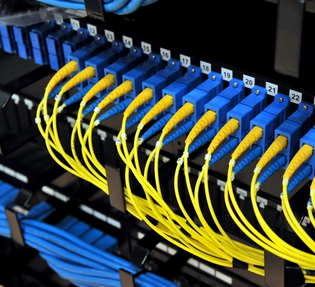
Image disclaimer: For identification and illustration only. It may show a product by another manufacturer and may not depict the exact item described; it is not a statement of any product’s quality, approval or performance. Third-party image and trademark rights belong to their owners. See full notice.
What Is It?
A Fibre Optic Patch Panel — also known as an optical distribution frame (ODF), fibre termination unit, or fibre management system — is a passive optical component that provides a centralised, organised termination point for fibre optic cables in a communication network. In AGL applications, the patch panel is installed in control rooms, equipment shelters, and substations to terminate fibre optic cables from remote field locations (e.g., runway edge cabinets, CCR substations, approach lighting shelters) and to provide flexible patching to active equipment (fibre converters, Ethernet switches, communication gateways, and the ALCMS server).
Key characteristics of the Fibre Optic Patch Panel include:
- Fibre Termination: Provides a secure, protected termination point for fibre optic cables using adapters (couplers) that accept standard fibre connectors (SC, LC, ST, or MTP/MPO).
- Cable Management: Includes cable guides, splice trays, and strain relief features to organise and protect fibre cables, preventing excessive bending and stress.
- High Density: Available in various port densities — from 12 ports to 144 ports or more — to accommodate the needs of large airfield communication networks.
- Modular Flexibility: Supports different adapter types and connector configurations, allowing easy reconfiguration as network requirements change.
- Protection and Security: Provides physical protection for fibre terminations through a lockable cover or door, preventing accidental damage and unauthorised access.
- Testing and Access: Allows easy access to fibre terminations for testing, troubleshooting, and reconfiguration using optical power meters, OTDRs, and visual fault locators.
In airfield lighting systems, fibre optic patch panels are essential for building a scalable, manageable optical backbone that connects the ALCMS server, switches, and gateways to remote field equipment. They ensure that fibre connections are organised, protected, and easily maintainable, supporting the high‑bandwidth, low‑latency communication required for modern AGL control and monitoring.
Purpose & Function
The patch panel's purpose, despite being entirely passive, is to keep a growing fibre network from becoming its own liability. As an airfield's optical backbone expands to reach more substations, runway cabinets, and shelters, an unorganised tangle of unlabelled fibre runs becomes genuinely dangerous to maintain — a technician tracing the wrong strand during a fault, or applying too tight a bend while working around unprotected cables, can take down links that had nothing to do with the original problem. By giving every fibre a fixed, labelled, protected termination point with proper strain relief, the panel is what lets a fault be isolated to a specific, identifiable link and repaired or rerouted quickly, rather than turning a communication fault into a lengthy cable-tracing exercise across the whole facility.
Where Is It Used?
Fibre Optic Patch Panels are deployed throughout the AGL communication infrastructure wherever fibre optic cables need to be terminated and interconnected. Key applications include:
- ALCMS Control Room: Central patch panels that terminate fibre cables from all remote substations, runway cabinets, and field sensors, providing a hub for connecting to the ALCMS server, switches, and workstations.
- CCR Substations: Patch panels that terminate fibre links from the control room and distribute connections to fibre converters and communication gateways within the substation.
- Runway Edge Cabinets: Ruggedised patch panels that terminate fibre cables from the airfield backbone and connect to local fibre converters and switches.
- Approach Lighting Shelters: Patch panels for terminating fibre cables to sequencer modules, flasher units, and remote I/O controllers.
- Remote Sensor Networks: Patch panels at weather station and sensor locations to terminate fibre links to the ALCMS.
- Inter‑building Cabling: Patch panels at building entry points to terminate incoming fibre cables and distribute them within the building.
- Equipment Shelters: Patch panels for fibre distribution between various communication devices (switches, gateways, converters) within the same shelter.
Installation & Location
The panel is rack-mounted or wall-mounted at the point where field fibre cables enter a control room, substation, runway cabinet, or equipment shelter, positioned so incoming cables have a short, protected run from their duct or conduit entry to the termination point without sharp bends or unsupported spans. Each incoming cable is secured with proper strain relief before its individual fibres are terminated into the panel's adapters, and any excess fibre length is coiled within the panel's built-in cable management rather than left loose, keeping bend radius within the fibre's rated minimum. The panel's lockable cover is kept closed and latched outside of active work, both to protect the terminations from dust and accidental damage and to control who can access a fibre plant that, once tampered with, can be difficult to fault-find. Panels at outdoor or unconditioned locations (runway cabinets, remote shelters) are specified with appropriately rated enclosures, while control-room installations use standard 19-inch rack panels sized to the port density needed for that location's cable count.
How Does It Work?
The Fibre Optic Patch Panel operates as a passive distribution and termination point, providing a centralised interface for managing fibre optic connections. Key functional aspects include:
- Fibre Termination: Incoming fibre optic cables (typically 2‑12 fibres per cable) are stripped, cleaved, and terminated with connectors (e.g., SC, LC, ST) that are inserted into adapters mounted on the patch panel's front face. Alternatively, fibres may be spliced to pigtails that are then terminated into adapters, using splice trays within the panel for protection.
- Adapter Interface: The adapters (couplers) on the panel provide a precision alignment between two fibre connectors, ensuring low insertion loss and minimal back reflection. They are typically duplex or simplex and support various connector types.
- Patching and Cross‑Connection: Patch cables (fibre optic jumpers) are used to connect ports on the patch panel to active equipment (fibre converters, switches, gateways) or to cross‑connect between different panels. This allows flexible routing of optical signals without re‑terminating cables.
- Cable Management: The panel includes cable guides, spools, and tie‑down points to manage both incoming fibre cables and patch cords. This prevents tight bends (which cause signal loss) and maintains a tidy, accessible installation.
- Splice Protection: Splice trays within the panel provide a protected environment for fusion splices (e.g., between incoming cables and pigtails). The trays hold the splices securely and allow for future re‑splicing if needed.
- Identification and Labelling: Each port on the patch panel is clearly labelled (typically with a numbering system and/or colour coding) to facilitate identification and troubleshooting. A label holder or enclosure front cover often includes a port mapping card.
- Testing and Maintenance: The panel provides easy access to each fibre termination for testing with an optical power meter, optical time‑domain reflectometer (OTDR), or visual fault locator. This allows technicians to verify signal integrity and identify faults.
The patch panel is typically installed in a 19" rack (1U to 4U height) or as a wall‑mount enclosure. It is constructed from durable materials (steel or aluminium) with a powder‑coated finish for corrosion resistance, and may include a transparent or lockable front cover for protection and security.
Cable Plant to Active Equipment & Control Logic
Incoming Fibre Cable
2–12 fibres terminated or spliced to pigtails in the tray
Splice Tray
Protects fusion splices, allows future re-splicing
Adapter Port
Precision-aligned SC/LC/ST coupler on the front face
Patch Cable
Jumper routes the signal to active equipment or another panel
Flexible, Testable Cross-Connect
Signals can be rerouted or measured (OTDR, power meter) without re-terminating any cable
Physical Construction
The panel body is a zinc-plated or powder-coated steel, or aluminium, chassis built to standard 19" rack dimensions (1U to 4U) or as a smaller gasketed wall-mount box, with the adapter plate — populated with SC, LC, ST, or MTP/MPO couplers — fixed across the front so patch cords connect from outside the enclosure while the permanent cable plant terminates inside. Incoming fibre cable enters through the rear or side with a strain-relief bracket and cable-management bar that sets a controlled bend radius before the fibres reach the splice trays or pigtail terminations mounted inside the chassis. Fusion splice trays, when fitted, hold individual splice protection sleeves in numbered slots so each fibre's route from field cable to front-panel adapter can be traced during maintenance, and a hinged or removable lid gives access to the splice area without disturbing the front-panel patch cords. Rack-mount units are left open (IP20) for indoor equipment-room use, while wall-mount versions add a gasketed door to reach IP54/IP65 for outdoor or unconditioned cabinet locations.
Technical Parameters
| Parameter | Typical Value |
|---|---|
| Form Factor | 19" rack‑mount (1U, 2U, 3U, 4U) or wall‑mount (IP20/IP54) |
| Port Density | 12, 24, 48, 72, 96, 144 ports (LC/SC duplex, MTP/MPO for high density) |
| Adapter Type | SC, LC, ST, MTP/MPO (mixed or single‑type, factory‑configured) |
| Connector Type Supported | SC APC/UPC, LC APC/UPC, ST, MTP/MPO (12‑24 fibres) |
| Fibre Type Supported | Single‑mode (OS1, OS2), Multi‑mode (OM1, OM2, OM3, OM4, OM5) |
| Insertion Loss (Adapter) | ≤ 0.2 dB (typical), ≤ 0.3 dB (max) for SC/LC |
| Return Loss (Adapter) | ≥ 50 dB (UPC), ≥ 60 dB (APC) |
| Splice Capacity | Up to 24‑48 fusion splices (included splice trays) |
| Cable Entry | Rear or side cable entry, with strain relief and cable management accessories |
| Material | Steel (zinc‑plated or powder‑coated) or aluminium |
| Protection Class | IP20 (indoor rack‑mount), IP54/IP65 (wall‑mount with gasketed cover) |
| Operating Temperature | -10°C to +60°C (indoor), -40°C to +70°C (outdoor) |
| Storage Temperature | -40°C to +85°C |
| Dimensions (Typical 2U) | 482.6mm × 88.9mm × 300mm (W × H × D) |
| Weight (Empty) | 3‑8 kg (depending on size and material) |
| Mounting | 19" rack (EIA‑310) or wall‑mount with keyhole slots |
| Certifications | CE, RoHS, REACH, IEC 61754 (connector standards), UL 94 (flammability) |
Applicable Standards
IEC 61754
Fibre optic connector interfaces (SC, LC, ST, MTP/MPO standards)
IEC 61300
Fibre optic interconnection devices — test and measurement procedures
ISO/IEC 11801
Information technology — generic cabling for customer premises
FAA AC 150/5345‑56
Specification for AGL control and monitoring equipment (fibre infrastructure)
Installation Requirements
Panel Mounting Position
MechanicalRack-mount or wall-mount the panel at the point where field fibre cables enter the room or cabinet, positioned so cables have a short, protected run from duct/conduit entry to the termination point.
Strain Relief & Bend Radius
MechanicalSecure each incoming cable with proper strain relief and coil excess fibre length within the panel's cable management, keeping bend radius within the fibre's rated minimum.
Fibre Termination & Splicing
ElectricalTerminate individual fibres into the panel's adapters or splice trays, numbering each slot so the route from field cable to front-panel adapter can be traced during maintenance.
Enclosure Rating Match
CivilConfirm the panel's enclosure rating matches its location — standard 19-inch rack panels indoors, or gasketed IP54/IP65 wall-mount enclosures at outdoor or unconditioned sites.
Cover Latching & Access Control
MechanicalConfirm the lockable cover closes and latches securely so terminations are protected from dust and accidental damage outside of active work.
Pre-Handover Sign-off
DocumentationRecord port assignments, splice/termination map, and cable entry details as-built before the panel is accepted into service.
Testing & Commissioning
Fibre Cleanliness Inspection
Pre-TerminationInspect every fibre end-face under a fibrescope before mating, since contamination is the leading cause of high insertion loss.
Insertion Loss Test
Final AcceptanceMeasure insertion loss at each adapter with an optical power meter/light source, confirming it meets the panel's rated spec (≤0.2-0.3 dB).
Return Loss Test
Final AcceptanceVerify return loss at each connector meets the UPC or APC polish rating, ruling out poor termination or contamination.
Fusion Splice Verification
Final AcceptanceConfirm each fusion splice meets its loss budget via OTDR trace, and that splice trays are correctly seated and protected.
Port Mapping & Labelling Verification
Final AcceptanceTrace and confirm each port's far-end connection matches the as-built fibre schedule, with labelling correct on both ends.
OTDR End-to-End Trace
Final AcceptanceRun an OTDR trace across each critical link to confirm total attenuation budget is met before the link is handed over for service.
Documentation & As-Built Sign-off
Final AcceptanceRecord insertion/return loss readings, splice test results, and the as-built port map in the commissioning dossier for handover.
Inspection & Maintenance
Connector Cleaning
AnnualClean all in-use connectors with a fibre optic cleaning kit and verify unused ports have protective dust caps fitted.
Cable Routing & Bend Radius Check
AnnualVerify patch cords and cable management guides maintain minimum bend radius to prevent signal loss.
Strain Relief Inspection
AnnualCheck cable clamps at entry points to confirm pulling force is applied to strength members, not the fibres themselves.
Adapter Inspection
AnnualInspect adapters for cracked ceramic sleeves or wear that could cause misalignment and high insertion loss, replacing as needed.
Port Labelling & Mapping Audit
AnnualReview the port mapping chart against actual connections to keep troubleshooting and reconfiguration straightforward.
Enclosure Seal Inspection
AnnualFor outdoor panels, check gaskets and cable glands remain sealed against moisture, dust, and temperature extremes.
Common Field Issues
High Insertion Loss due to Dirty Connectors
Contamination on fibre connectors (dust, oil, debris) is a leading cause of high insertion loss. Always clean connectors with a fibre optic cleaning kit (e.g., pen cleaner, wipes) before mating. Use protective dust caps on unused ports.
Excessive Bend Loss
Fibre optic cables and patch cords have a minimum bend radius (typically 30‑50mm for single‑mode). Exceeding this can cause significant signal loss. Use cable management guides and ensure patch cords are not tightly kinked or crushed.
Fibre Breakage due to Strain
Improper strain relief at cable entry points can cause fibre breakage. Ensure cables are securely clamped and that any pulling force is applied to the cable strength members, not the fibres themselves.
Incorrect Polarity
In duplex fibre connections, reversing the transmit and receive fibres will cause communication failure. Maintain consistent polarity (A‑B, A‑B) across all connections and use polarity‑managed transceivers or cross‑over patch cords as required.
Adapter Alignment Issues
Damaged or worn adapters can cause misalignment, leading to high insertion loss. Inspect adapters regularly and replace any that show signs of damage or wear (e.g., cracked ceramic sleeves).
Inadequate Labelling
Poor labelling of patch panel ports makes troubleshooting and reconfiguration difficult. Maintain a clear, updated port mapping chart (physical and/or digital) and use colour‑coded cables or labels for different fibre types or network segments.
Environmental Damage (Outdoor Panels)
Outdoor patch panels can be affected by moisture, dust, and temperature extremes. Ensure proper sealing (gaskets, cable glands) and use outdoor‑rated panels (IP54/IP65) with corrosion‑resistant materials.
Troubleshooting Guide
High Insertion Loss on a Specific Link
Signal Loss With No Visible Connector Contamination
Sudden, Complete Loss of Link at the Panel
Link Established but No Data Communication
Consistently High Loss at One Specific Port
Difficulty Locating or Identifying a Specific Fibre Run
Performance Degradation on an Outdoor Panel
Failure Modes & Root Causes
Connector End-Face Contamination
Sub-Surface Fibre Damage
Fibre Break at the Panel
Wavelength or Duplex Mismatch
Excessive Bend Radius at a Port
Missing or Faded Fibre Labelling
Outdoor Panel Environmental Degradation
Safety & Operational Notes
Never Look Into a Live Fibre or Connector
Optical SafetyTreat every fibre end and connector as potentially carrying an active laser source; never look directly into a fibre, connector, or transceiver port, and confirm the link is shut down before inspecting an end-face by eye.
Bare Fibre Handling
Personnel SafetyHandle stripped or broken fibre offcuts with care and dispose of them in a sharps-style container; glass fragments are easily embedded in skin and are difficult to see or remove.
Connector Cleaning Discipline
ComplianceClean and inspect every connector end-face before mating using approved fibre-cleaning tools; contamination is the leading cause of degraded links and can permanently damage a connector if mated dirty.
Respect Minimum Bend Radius
MechanicalRoute and dress patch cords within the panel's specified bend radius; over-tight bends increase attenuation and can crack the fibre core without any visible external damage.
Electrical Safety of Co-Located Equipment
Electrical SafetyThe panel itself is passive, but it is typically mounted alongside powered converters, switches, and gateways; follow standard electrical safety and lockout procedures for that equipment when working in the same rack or cabinet.
Positive Identification Before Disconnecting
OperationalConfirm circuit labelling and cross-reference documentation before removing a patch cord in service, since an unplanned disconnection can silently drop communications to a remote CCR substation or shelter.
Verify Link Performance After Work
ComplianceCheck link status or optical power levels after any re-termination or patching change before leaving the site, to confirm the connection is within acceptable loss margins.
Engineering & Expert Notes
Dirty Connectors Are the Leading Cause of Intermittent Faults, Not Fibre Breaks
OpticalA fibre link with degraded signal quality is far more often caused by contamination on a connector end-face than by an actual break in the fibre; inspect and clean connector end-faces with a fibre scope before assuming a cable-level fault.
Respect Minimum Bend Radius Inside the Panel, Not Just Along the Run
InstallationFibre routed tightly inside the patch panel to save space can exceed minimum bend radius even when the outside cable run is perfectly compliant; excessive bend inside the panel causes signal loss that's easy to overlook since it's hidden from view once the panel is closed.
Keep the Panel Labeling Synchronised With the Actual Patching, Not Just the Original Design
DocumentationPatch panels accumulate undocumented re-patches over years of troubleshooting and moves; a periodic audit comparing physical patching against labeled records prevents a technician from working on the wrong circuit during future fault-finding.
Never Look Directly Into a Fibre End-Face Without Confirming the Source Is Off
SafetySome fibre transmission equipment uses invisible infrared light that can cause eye damage without any visible warning sign; treat every fibre end-face as potentially live and use a proper optical power meter to check status, never a direct visual check.
Confirm the Shelter's Climate Control Is Actually Functioning, Not Just Installed
EnvironmentalFibre transceivers and active equipment behind the patch panel are more temperature-sensitive than the passive panel itself; verify the equipment shelter's HVAC is genuinely maintaining spec temperature rather than assuming its presence is sufficient.
Re-Test Loss Budget After Any Re-Patching Campaign
ProcessCumulative insertion loss from repeated re-patching over time can push a link close to its loss budget even if each individual re-patch seemed insignificant; periodically re-verify end-to-end loss against budget rather than assuming original commissioning figures still hold.
Frequently Asked Questions
Short answers about fibre optic patch panels in AGL systems: what they do, port types, installation, standards, maintenance and common faults.
Q1What is a fibre optic patch panel?
A fibre optic patch panel, also called an optical distribution frame (ODF) or fibre termination unit, is a passive component that gives a centralised, organised termination point for fibre cables. In AGL it terminates fibre from remote sites such as runway edge cabinets, CCR substations and approach lighting shelters and allows flexible patching to active equipment.
Q2Where are fibre optic patch panels used in an AGL system?
In ALCMS control rooms, CCR substations, runway edge cabinets, equipment shelters and other points where field fibre cables must be terminated. They connect to fibre converters, Ethernet switches, communication gateways and the ALCMS server.
Q3Why does an airfield need a patch panel?
As an optical backbone grows, unlabelled fibre runs become a maintenance risk. A technician tracing the wrong strand or bending unprotected cable too tightly during a fault can take down communications. A patch panel keeps terminations organised, labelled and protected.
Q4How are fibres terminated in a patch panel?
Incoming cables, typically with 2–12 fibres, are stripped and terminated with connectors such as SC, LC or ST that plug into adapters on the front face, or fibres are spliced to pigtails held in splice trays inside the panel. Each cable is secured with strain relief first.
Q5What port counts and connector types are available?
Typical port counts are 12, 24, 48, 72, 96 and 144, with SC, LC, ST or MTP/MPO adapters. Panels support single-mode (OS1, OS2) and multi-mode (OM1 to OM5) fibre in 19-inch rack-mount (1U to 4U) or wall-mount form.
Q6What insertion loss should a patch panel adapter have?
Adapter insertion loss is typically 0.2 dB or less and no more than 0.3 dB at maximum for SC and LC. Return loss is at least 50 dB for UPC and at least 60 dB for APC.
Q7What is the minimum bend radius for fibre cables?
Typically 30–50 mm for single-mode fibre. Patch cords and cables should follow cable management guides so they are never bent tighter than their rated minimum, since tight bends and kinks cause signal loss.
Q8Which standards apply to fibre optic patch panels?
The main references are IEC 61754 (fibre optic connector interfaces), IEC 61300 (interconnection device test and measurement), ISO/IEC 11801 (generic cabling) and FAA AC 150/5345-56 (AGL control and monitoring equipment, including fibre infrastructure). Always verify the current edition and your approved requirements.
Q9How often should a fibre optic patch panel be maintained?
Typically annually: clean in-use connectors and confirm dust caps on unused ports, check bend radius and cable routing, inspect strain relief and adapters, audit port labelling against the mapping chart and, for outdoor panels, inspect enclosure seals. Your approved maintenance programme takes precedence.
Q10Why is a fibre link showing high insertion loss or signal loss?
Dirty connector end-faces from dust, oil or debris are a leading cause, so clean them with a fibre cleaning kit and fit dust caps on unused ports. If the connectors are clean, look for excessive bend loss from a patch cord bent below its minimum radius or a crushed or kinked cable, and re-route it.
Related Components
Go Beyond the Component. Understand the Complete AGL System.
You have explored the component. Now understand how it works within the complete Airfield Ground Lighting system.
Learn AGL from fundamentals to design, installation, testing, photometry, commissioning, maintenance and troubleshooting through structured technical training at Precision AGL Academy.
Build practical knowledge. Understand the circuit. Read the standards. Troubleshoot with confidence.
Your next step in AGL starts here.
Need expert guidance on Fibre Optic Patch Panel selection, installation, or cable management for your AGL network?
Precision AGL Academy provides advice on panel density, connector types, cable management strategies, and best practices for reliable fibre infrastructure.
Follow the Academy
Important Notice, Disclaimer & Limitation of Liability
Please read before relying on any content on this page.
- Purpose and intended users. This page on Fibre Optic Patch Panel is an independent educational and informational reference for competent, suitably trained and authorised airfield ground lighting (AGL) and aerodrome electrical personnel. It is not professional engineering, legal or regulatory advice, and using it does not create any professional or client relationship.
- Safety. Work on series circuits, constant current regulators (CCRs), isolating transformers, cables, connectors and lighting equipment can be fatal. Always apply the aerodrome’s permit-to-work and isolation/LOTO procedures, prove dead, use correctly rated instruments and PPE, and follow the manufacturer’s instructions. Nothing here authorises work on live equipment or the bypassing of any safety device or interlock.
- Aviation operations. Nothing here authorises installation, modification, energisation, adjustment, return to service, a change of operating category (CAT I/II/III), a NOTAM or any aerodrome certification or approval decision. These rest with the aerodrome operator, the air navigation service provider and the competent regulator.
- Specifications, ratings and typical values. Descriptions, parameters, ratings, dimensions, photometric values, wattages, service lives, maintenance tasks and intervals, failure modes, certifications (for example CE, FCC, UL or IEC marks) and part or type designations are general, typical and indicative. They may not match any particular product, make, model or version, and they are not a datasheet, design, specification, selection, sizing, procurement or acceptance criterion. The manufacturer’s current documents, the approved design and the project specification prevail.
- Standards and regulations. References to ICAO, FAA, IEC, IEEE, ISO, BIS, DGCA and other standards are paraphrased summaries for orientation only. They may be incomplete or out of date, and standards are revised from time to time. Consult the current official editions. Following this content does not guarantee compliance with any law, standard or regulatory approval, and the regulator’s requirements always prevail.
- No warranty. Content is provided “as is” and “as available”, without warranty of any kind, express or implied, including accuracy, completeness, currency or fitness for a particular purpose. Real installations differ in design, equipment make and model, age and condition.
- Limitation of liability. To the fullest extent permitted by applicable law, Precision AGL Academy, Precision AGL Solutions and their owners, authors and contributors are not liable for any injury, death, loss, damage, downtime, penalty or regulatory consequence, whether direct or indirect, arising from the use of, reliance on, or inability to use this content. Nothing in this notice excludes or limits any liability that cannot lawfully be excluded or limited.
- Independence, brands and no endorsement. This is an independent publication. It is not affiliated with, sponsored by or endorsed by ICAO, the FAA, the IEC, DGCA, AAI, any airport, regulator, supplier or equipment manufacturer. Third-party names, product designations, standard designations and trademarks (including Megger®, Siemens, Eaton, Crouse-Hinds, ADB SAFEGATE, Fluke, ABB and Honeywell) belong to their respective owners and are used only for identification and description. Mention of a brand, product or supplier is not a recommendation, and we do not sell, supply or quote for any component described.
- Images and third-party content. Images and illustrations are shown to help identify the type of component. They may show products of various manufacturers, may not depict the exact item described, and are not a statement about any product’s quality, approval or performance. Copyright and trademarks in third-party images, logos and photographs belong to their respective owners and are not claimed as ours. If you are a rights holder and want an image removed, replaced or credited, email precisionaglsolutions@gmail.com with the page address and we will act promptly.
- Training and services. Mentions of training, courses, consultation, advice, selection, installation, calibration or other support, including the “Learn…Certify” pathway, describe learning stages and are not an offer, quotation, tender or promise of any result. Contacting us or our replying creates no engagement or duty of care; an engagement exists only under a written agreement. We are not a regulator or certification body, and completing any course or reading this content is not a certification, accreditation or authorisation to work on any aerodrome.
- Copyright, privacy and corrections. © 2026 Precision AGL Academy. All rights reserved. Text, structure, compilations and diagrams may be viewed for personal reference and internal training only; any other copying, republication or commercial use needs our written permission. If you email, telephone or message us, we use your details only to respond and handle your matter, in line with applicable Indian law including the Digital Personal Data Protection Act, 2023; please do not send confidential or security-sensitive information. To display this page your browser requests fonts, icons and images from third-party servers, which receive your IP address and browser details under their own policies. Content is reviewed periodically with no obligation to update. To report an error, safety concern or rights issue, write to precisionaglsolutions@gmail.com.