LED Technology in AGL Systems
The transformative shift from halogen to solid‑state lighting — delivering longer life, lower power consumption, instant restrike, and precise photometric control, while challenging traditional series‑circuit compatibility and retrofit strategies.
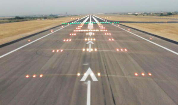
Image disclaimer: For identification and illustration only. It may show a product by another manufacturer and may not depict the exact item described; it is not a statement of any product’s quality, approval or performance. Third-party image and trademark rights belong to their owners. See full notice.
What Is It?
LED (Light Emitting Diode) technology has revolutionised airfield ground lighting. Unlike halogen or incandescent lamps that produce light by heating a filament, LEDs are solid‑state devices that emit light when current passes through a semiconductor junction. The result is higher efficacy (lumens per watt), dramatically longer life (50,000+ hours vs. 1,000–2,000 for halogen), and the ability to produce precise colours without filters.
In AGL systems, LEDs are now the default choice for new installations and are increasingly being retrofitted into existing fixtures. However, their electrical characteristics (low forward voltage, need for constant current drive, and sensitivity to reverse polarity) require careful integration with the traditional series‑circuit architecture and CCRs. The transition involves not just swapping lamps, but often replacing the entire light engine and sometimes the isolating transformer or its secondary circuit.
Purpose & Function
A pilot judging a runway's edges or a stop bar at night is trusting that every fixture in the circuit is still producing the intensity it was commissioned at — a halogen lamp's filament degrades gradually and largely invisibly between scheduled photometric checks, so a fixture can be running under-intensity for months before anyone notices. LED technology's purpose in AGL is not simply efficiency: its stable, near-constant light output over a very long service life closes that gap, keeping the fixture closer to its rated intensity for far longer, while also reducing how often technicians need to be out on live movement areas to replace lamps — itself a source of airside safety exposure. Realising that benefit is also why LEDs cannot simply be dropped into existing fixtures: because the series circuit and CCR are built to regulate constant current rather than constant voltage, the LED driver and light engine have to be engineered to work within that architecture, which is why an LED retrofit is frequently a light-engine and transformer change rather than a lamp swap.
Where Is It Used?
LEDs have been adopted across the full range of AGL fixtures, with varying levels of maturity:
- Runway Edge and Centreline: LED versions of elevated and inset fixtures are now standard. They offer better intensity control and longer intervals between maintenance.
- Taxiway Edge and Centreline: Blue and green LED edge/centreline lights are widely used, with improved colour stability over lamp life.
- Approach Lighting: LED approach light bars and crossbars are common, with some systems using pulsed LED for sequenced flashing.
- PAPI / VASI: LED PAPI units are replacing halogen, providing sharper colour transition and lower energy consumption.
- Stop Bars and Guard Lights: Red and yellow LED stop bars and guard lights are standard, with faster switching for dynamic control.
- Airfield Signage: LED‑lit signs are more uniform and easier to maintain than fluorescent or lamp‑lit versions.
- Obstruction Lighting: LED obstruction lights are the de facto choice for all intensity classes, often with solar options.
Retrofit kits are available for many legacy fixtures, allowing airports to upgrade without replacing the entire housing, though compatibility with the existing series circuit and transformer must be verified.
Installation & Location
LED light engines are fitted inside the existing fixture housing in the same position the halogen lamp and reflector previously occupied, but because LEDs run on regulated constant current rather than the higher voltage a halogen lamp tolerates, an isolating transformer swap or secondary-side adjustment is usually part of the same installation rather than a separate step. Retrofit installation is normally done fixture by fixture on a live circuit, with each unit taken out of service, the halogen lamp assembly and reflector removed, the new LED module and driver fitted and wired to the transformer secondary, and the fixture returned to service and intensity-checked before moving to the next; this staged approach keeps the runway or taxiway circuit largely operational throughout the changeover rather than requiring the whole circuit to go dark at once. Compatibility between the new LED load and the existing transformer's regulation characteristics is verified at each fixture during installation, since an LED module's low forward voltage and constant-current requirement do not always suit a transformer that was originally sized and wound for a halogen load.
How Does It Work?
In an LED AGL fixture, the LED module is driven by a constant‑current driver circuit that accepts the AC secondary voltage from the isolating transformer and converts it to a regulated DC current suitable for the LEDs. The driver may also incorporate dimming or pulse‑width modulation (PWM) to achieve the required intensity steps, which are typically controlled by the primary current level (the same 2.8A / 3.4A / 4.1A / 5.2A / 6.6A CCR steps used for halogen fixtures).
Key functional aspects include:
- Colour Control: LEDs produce light in specific wavelengths; red, green, blue, and white LEDs are available without filters, leading to more accurate and stable colours over life.
- Dimming and Intensity Steps: LED drivers can be designed to respond to the primary current level by reducing LED current or using PWM to emulate lower intensities. This ensures compatibility with existing CCR step settings.
- Instant Restrike: LEDs reach full brightness immediately, unlike halogen lamps that require a warm‑up time. This is advantageous for stop bars and other rapidly switched applications.
- Thermal Management: LEDs generate heat at the junction, which must be conducted away via heat sinks or active cooling. Proper thermal design is critical to maintain life and colour stability.
- Optical Design: LEDs are small point sources, allowing advanced optical systems (lenses, reflectors) to shape the beam precisely to meet photometric requirements without the bulk of halogen reflectors.
System Architecture & Control Logic
Inside an LED AGL fixture, the driver circuit is itself a small closed-loop controller: it accepts the AC secondary voltage from the isolating transformer, rectifies and regulates it, and continuously senses the current actually flowing through the LED array, adjusting its output to hold that current at the level the LEDs require regardless of supply variation or thermal drift. The primary-side intensity step set by the CCR is read by the driver as an input signal, which the driver translates into the corresponding LED current or PWM duty cycle, so the fixture's visible brightness tracks the same step commands used for legacy halogen fixtures without any separate control channel. A thermal management loop runs alongside the current loop: temperature sensed at the LED junction or heat sink feeds back into the driver, which derates current if the junction runs hot, protecting lumen output and colour stability at the cost of a small, self-limiting intensity reduction rather than an outright failure.
Transformer Secondary → LED Driver → Current/Thermal Feedback → LED Array → Beam Output
From Secondary Voltage to Beam
AC Secondary
Voltage arrives from the isolating transformer
LED Driver
Rectifies & regulates a constant current, applies PWM
LED Junction
Semiconductor emits light at a specific wavelength
Optics
Small point source shaped precisely by lens/reflector
Intensity Steps Match Existing CCR Settings
Heat sinks or active cooling carry away junction heat to preserve life & colour stability
Physical Construction
An AGL LED light engine is built around one or more semiconductor LED die mounted on a metal-core printed circuit board (MCPCB), chosen for its ability to conduct heat away from the junction efficiently, since LED lifetime and light output both degrade rapidly if junction temperature is allowed to rise excessively. The MCPCB is thermally bonded, typically with a thermal interface pad or paste, to a heat sink integrated into the fixture housing, which may be finned aluminium or simply the die-cast housing itself acting as a heat spreader. A driver circuit, converting the transformer secondary's AC or DC output into the regulated current the LED array requires, is housed in a separate potted or conformal-coated module within the fixture, protected from moisture and vibration to the same ingress protection standard as the rest of the luminaire. Optical elements, whether a moulded lens, reflector, or diffuser, are positioned directly over the LED array to shape the beam pattern, and the entire light engine assembly is gasket-sealed within the fixture housing so the LED array and its electronics remain protected while still allowing heat generated at the die to conduct outward to the ambient air.
Technical Parameters
| Parameter | Typical Value |
|---|---|
| Luminous Efficacy | 100–200 lm/W (depending on colour and quality) |
| Lifetime (L70) | 50,000 – 100,000 hours (to 70% initial flux) |
| Colour Temperature (White) | Typically 5,000–6,500 K (daylight) or 2,700–3,000 K (warm) |
| Colour Rendering Index (CRI) | Typically 70–80 (white); not critical for most AGL |
| Forward Voltage (per LED) | 2–3 V (red) to 3–4 V (white/blue) |
| Driver Input | 6.6V or 12V AC (from transformer secondary) or sometimes direct DC |
| Intensity Control | Primary current‑sensing or PWM control; compatible with 6.6A steps |
| Operating Temperature | -40°C to +55°C (ambient), junction temperature typically ≤85°C |
| Ingress Protection | IP68 (for buried/inset fixtures) |
| Standards | FAA AC 150/5345‑53 (Airport Lighting Equipment Certification Program) with Engineering Brief #67 (LED/alternative light sources), ICAO Annex 14, IEC 61822 |
Electrical Requirements
| Requirement | Typical Value |
|---|---|
| Driver Input | 6.6V or 12V AC from isolating transformer secondary, or direct DC in some designs |
| Intensity Control | Primary current-sensing or PWM, compatible with 6.6A CCR steps |
| Cable Type | Short secondary leads to LED driver, rated for the secondary voltage class |
| Insulation Resistance | ≥ 20 MΩ (secondary circuit to case ground) |
| Earthing/Grounding | LED module heatsink/housing bonded to fixture body earth |
| Fault Protection | Driver-level over-current and over-temperature protection; upstream CCR fault detection on the primary loop |
| Power Source | Fed from the fixture's isolating transformer, ultimately sourced from the CCR series loop |
Photometric Requirements
| Parameter | Typical Value |
|---|---|
| Luminous Flux Maintenance (L70) | ≥ 70% of initial flux retained through rated lifetime (50,000–100,000 hours) |
| Chromaticity Stability | Colour point remains within the applicable ICAO Annex 14 boundary throughout lamp life |
| Colour Consistency (Binning) | ≤ 3-step MacAdam ellipse across a production batch, for uniform fixture-to-fixture appearance |
| Intensity Step Linearity | Output tracks the CCR's 3- or 5-step current schedule within ± 25% at each step |
| Thermal Derating | ≤ 10% flux loss at maximum rated junction temperature (~85°C) versus 25°C reference |
| Isocandela Distribution | Matched to the host fixture's ICAO Annex 14 Attachment A figure, or the applicable FAA fixture AC (AC 150/5345-46) as qualified under Engineering Brief #67 |
| Intensity Tolerance | ± 25% of rated value at each CCR step (field measurement) |
| Test Method | Integrating sphere/goniophotometer at manufacture; mobile photometric van or fixed test bench in the field |
Applicable Standards
FAA AC 150/5345‑53 & EB #67
Airport Lighting Equipment Certification Program, with Engineering Brief #67 covering LED/alternative light-source design and test requirements
FAA AC 150/5345‑56
Control and monitoring systems, includes LED compatibility
ICAO Annex 14
International standards for AGL, including photometric performance for LED fixtures
IEC 61822
Constant current regulator (CCR) requirements for the series circuit the LED fixture's driver operates on
IEC TS 61827
Characteristics of inset and elevated luminaires, incl. LED light source performance
IS 7785
Indian Standard for airfield lighting equipment, with amendments for LED technology
Installation Requirements
Driver-to-Transformer Compatibility
ElectricalConfirm the LED driver's input voltage and current requirements match the isolating transformer's secondary output before connection, since a retrofit often needs the transformer or secondary circuit replaced alongside the lamp.
Polarity Observance
ElectricalWire the LED array and driver to the correct polarity, since LEDs are sensitive to reverse polarity in a way conventional lamps are not.
Current Step Compatibility
ElectricalConfirm the driver's intensity control (current-sensing or PWM) responds correctly across the CCR's 6.6A step range before the fixture is returned to service.
Thermal Bond to Heat Sink
MechanicalBond the MCPCB to the fixture's heat sink with the specified thermal interface pad or paste, since LED lifetime and light output both degrade rapidly if junction temperature is allowed to rise.
Optical Alignment
MechanicalSeat the lens, reflector, or diffuser directly over the LED array in its designed position, since the beam pattern depends on this alignment more than on the lamp it replaces.
Gasket Re-Sealing
MechanicalRenew the housing gasket around the light engine module when retrofitting, restoring the fixture's original ingress protection rating rather than reusing a worn seal.
Pre-Energisation Sign-off
DocumentationRecord the driver/transformer pairing and thermal bond confirmation as-built before the fixture is closed up and returned to service.
Testing & Commissioning
Insulation Resistance Test
Pre-EnergisationMegger-test the LED driver circuit and secondary wiring before the fixture is sealed and backfilled, confirming insulation resistance clears the acceptable minimum.
Forward Voltage & Drive Current Verification
EnergisationWith the CCR energised, confirm LED array forward voltage and drive current at the transformer secondary match the design values for the fixture type.
Intensity Step Response Test
EnergisationCycle the CCR through every current step and confirm the current-sensing or PWM driver produces the correct proportional light output at each step.
Colour Temperature & CRI Verification
Final AcceptanceMeasure colour temperature (and CRI where relevant) with a calibrated colorimeter or spectroradiometer, confirming the array meets the specified white or coloured output.
Thermal Performance Check
Final AcceptanceRun the fixture at full intensity for a sustained period and confirm LED junction temperature stays within its rated limit (typically ≤85°C) to protect long-term lumen maintenance.
Photometric Commissioning Test
Final AcceptanceMeasure luminous intensity and efficacy with a calibrated photometer against ICAO/FAA LED fixture commissioning tolerances prior to handover.
Documentation & As-Built Sign-off
Final AcceptanceRecord insulation, drive-current, thermal, and photometric readings alongside as-built fixture positions in the commissioning dossier for handover.
Inspection & Maintenance
Luminous Flux / Lumen Depreciation Check
AnnualMeasure output against baseline to track progress toward the L70 lifetime point (50,000–100,000 hours), flagging arrays nearing end of useful life.
Colour Temperature / Rendering Check
AnnualVerify white LEDs remain within the specified colour temperature range, since drift can indicate uneven ageing across the array.
Driver / Intensity Control Check
Semi-annualConfirm the current-sensing or PWM driver correctly tracks all 6.6A intensity steps and maintains stable output at each level.
Junction Temperature Check
AnnualCheck thermal management and heat-sinking so LED junction temperature stays at or below the 85°C threshold, since overheating accelerates lumen depreciation.
Forward Voltage Verification
AnnualMeasure forward voltage per LED string to detect individual diode degradation before it causes visible dimming or colour shift.
Seal / IP68 Integrity Check
AnnualInspect the LED module housing seal on buried/inset fixtures, since moisture ingress into the array is a leading cause of premature LED failure.
Driver Input Voltage Check
AnnualConfirm the 6.6V/12V AC input from the transformer secondary stays within the driver's rated range.
Lens / Optic Cleaning
QuarterlyClean the lens or optic covering the LED array of dust and film build-up so measured output reflects true LED condition rather than surface contamination.
Common Field Issues
Driver Failure
The LED driver is the most failure‑prone component in an LED fixture. Voltage spikes, thermal stress, or component ageing can cause driver failure, often without visible damage to the LEDs themselves.
Colour Shift Over Time
White LEDs can exhibit colour temperature shift (usually towards yellow/blue) as they age. This is less of an issue for monochromatic (red, green) LEDs, but must be monitored for uniform appearance.
Thermal Management Failure
If heat sinks are clogged with dust or the fixture is poorly installed, the LED junction temperature can rise, accelerating lumen degradation and shortening life.
Compatibility with Existing Transformers
Some LED retrofits require a specific secondary voltage or current. Mismatched transformers can cause over‑ or under‑driving, reducing performance or damaging the driver.
Electromagnetic Interference (EMI)
Switching drivers can generate EMI that may interfere with other airfield systems (e.g., communications). Compliance with EMC standards is essential.
Intensity Step Mismatch
If the driver does not correctly interpret the primary current levels, the fixture may not dim uniformly or may not achieve the required step values, leading to non‑compliance with photometric testing.
Troubleshooting Guide
Fixture Dark, No Output at All
Visible Colour Shift Between Fixtures
Progressive Lumen Loss / Early Dimming
Fixture Over- or Under-Driven After Retrofit
EMI Interference Reported by Nearby Systems
Uneven Dimming Across Intensity Steps
Failure Modes & Root Causes
Complete LED Fixture Failure
Colour Consistency Drift Between Fixtures
Progressive Lumen Depreciation
Driver Mismatch After Retrofit
EMI Emission from LED Drivers
PWM Dimming Instability
Safety & Operational Notes
Electrical Isolation Before Driver Work
Electrical SafetyDe-energise and lock out the CCR or supply circuit before opening a fixture housing to inspect or replace an LED module or driver, and verify zero energy at the fixture before handling connections.
Verify Driver-to-CCR Compatibility Before Retrofit
Electrical SafetyConfirm a retrofit LED driver is correctly matched to the CCR's output characteristics before energising the fixture; a mismatch can over- or under-drive the LEDs, risking premature failure or output that falls below the required photometric threshold without an obvious fault indication.
Match LED Bin on Replacement
OperationalSource replacement fixtures or modules from a matched LED bin where possible, and check chromaticity against neighbouring fixtures on the same circuit after installation, since bin variation between batches can create a visible colour shift along a lit surface.
EMI Awareness Near Sensitive Equipment
OperationalIf EMI interference is reported by nearby communication or navigation equipment, investigate the driver's switching frequency and EMI filter condition before assuming an unrelated cause, and replace a driver confirmed as the source rather than working around the symptom.
Thermal Management
OperationalEnsure heat sinking and enclosure seals are correctly reinstated after any driver or module work, since sustained operation at elevated junction temperature accelerates lumen depreciation and shortens LED service life.
Verify Output Across All Intensity Steps
ComplianceAfter any driver replacement or firmware change affecting dimming, check for visible flicker or stepping inconsistency across all intensity steps before closing out the work, since PWM dimming instability is often step-specific rather than uniform.
PPE & Grounding
Personnel SafetyUse insulated tools and appropriate PPE when working on driver or power connections, and confirm the fixture is bonded/grounded per the electrical design before reconnecting supply.
Restore to Compliant State
ComplianceDo not leave a fixture in service with unverified driver output, colour, or dimming behaviour after any retrofit or repair; confirm photometric and chromaticity conformance before closing out the work.
Airport Lighting LED Fixture
An airport lighting LED fixture uses an LED module and driver in place of a lamp. It gives a long service life, colour without filters and lower power use. On a series circuit, the LED load must be compatible with the isolating transformer and CCR, so check the power factor, the rated current and the transformer rating before replacing lamps. See the LED module and LED driver pages.
Engineering & Expert Notes
L70 Lifetime Is a Statistical Point, Not a Guarantee
ReliabilityL70 ratings describe the population median time to 70% lumen output under specified test conditions; individual modules in a hot, dusty apron environment can fall below threshold well before the rated hours. Treat L70 as a planning input for budget cycles, not a promise for any single fixture.
Constant-Current vs Constant-Voltage Topology Sets Retrofit Compatibility
ElectricalSeries airfield circuits expect a constant-current load response; a driver designed around constant-voltage assumptions can behave unpredictably as CCR output current steps change. Confirm the driver topology matches the series circuit before specifying a retrofit, not just its input voltage range.
Thermal Derating Margins Shrink Fast on Hot Aprons
ThermalManufacturer lumen and lifetime figures are usually quoted at a moderate ambient; a fixture on a sun-facing apron in a hot climate can run well above that reference temperature for much of the day. Check the driver's derating curve against actual site ambient, not the datasheet's test condition.
Match Surge Protection to the Loop's Real Exposure
ElectricalA driver's built-in surge suppression is sized for typical conditions, not every site. Loops with long overhead runs or high lightning-strike density benefit from supplemental surge protection sized to the loop's actual exposure, evaluated separately from the fixture's stock rating.
Binning Tolerance Belongs in the Purchase Spec
DesignChromaticity and flux binning vary batch to batch even within one manufacturer's product line. Specify an acceptable binning tolerance at the purchasing stage, rather than discovering colour or brightness mismatch after installation next to existing fixtures.
Dimming Step Response Time Affects Perceived Uniformity
PerformanceSome LED drivers step to a new brightness level noticeably faster or slower than others when the CCR changes current. On a shared loop with mixed fixture ages, uneven step response time can make brightness transitions look staggered even when steady-state output matches.
Frequently Asked Questions
Short answers about the LED Technology in AGL Systems: what it is, how it works, typical specifications, standards, maintenance and common faults.
Q1What is LED Technology in AGL Systems?
LED (Light Emitting Diode) technology has revolutionised airfield ground lighting. Unlike halogen or incandescent lamps that produce light by heating a filament, LEDs are solid‑state devices that emit light when current passes through a semiconductor junction. The result is higher efficacy (lumens per watt), dramatically longer life (50,000+ hours vs. 1,000–2,000 for halogen), and the ability to produce precise colours without filters. In AGL systems, LEDs are now the default choice for new installations and are increasingly being retrofitted into existing fixtures.
Q2What is the purpose of LED Technology in AGL Systems?
A pilot judging a runway's edges or a stop bar at night is trusting that every fixture in the circuit is still producing the intensity it was commissioned at — a halogen lamp's filament degrades gradually and largely invisibly between scheduled photometric checks, so a fixture can be running under-intensity for months before anyone notices.
Q3Where is LED Technology in AGL Systems used and installed?
LEDs have been adopted across the full range of AGL fixtures, with varying levels of maturity: Runway Edge and Centreline: LED versions of elevated and inset fixtures are now standard. They offer better intensity control and longer intervals between maintenance. Taxiway Edge and Centreline: Blue and green LED edge/centreline lights are widely used, with improved colour stability over lamp life. Approach Lighting: LED approach light bars and crossbars are common, with some systems using pulsed LED for sequenced flashing.
Q4How does LED Technology in AGL Systems work?
In an LED AGL fixture, the LED module is driven by a constant‑current driver circuit that accepts the AC secondary voltage from the isolating transformer and converts it to a regulated DC current suitable for the LEDs. The driver may also incorporate dimming or pulse‑width modulation (PWM) to achieve the required intensity steps, which are typically controlled by the primary current level (the same 2.8A / 3.4A / 4.1A / 5.2A / 6.6A CCR steps used for halogen fixtures).
Q5What are the typical technical parameters of LED Technology in AGL Systems?
Typical values are — Luminous Efficacy: 100–200 lm/W (depending on colour and quality); Lifetime (L70): 50,000 – 100,000 hours (to 70% initial flux); Colour Temperature (White): Typically 5,000–6,500 K (daylight) or 2,700–3,000 K (warm); Colour Rendering Index (CRI): Typically 70–80 (white); not critical for most AGL; Forward Voltage (per LED): 2–3 V (red) to 3–4 V (white/blue); Driver Input: 6.6V or 12V AC (from transformer secondary) or sometimes direct DC; Intensity Control: Primary current‑sensing or PWM control; compatible with 6.6A steps; Operating Temperature: -40°C to +55°C (ambient), junction temperature typically ≤85°C.
Q6What are the electrical requirements for LED Technology in AGL Systems?
Typical requirements are — Driver Input: 6.6V or 12V AC from isolating transformer secondary, or direct DC in some designs; Intensity Control: Primary current-sensing or PWM, compatible with 6.6A CCR steps; Cable Type: Short secondary leads to LED driver, rated for the secondary voltage class; Insulation Resistance: ≥ 20 MΩ (secondary circuit to case ground); Earthing/Grounding: LED module heatsink/housing bonded to fixture body earth; Fault Protection: Driver-level over-current and over-temperature protection; upstream CCR fault detection on the primary loop; Power Source: Fed from the fixture's isolating transformer, ultimately sourced from the CCR series loop.
Q7What photometric requirements apply to LED Technology in AGL Systems?
Typical requirements are — Luminous Flux Maintenance (L70): ≥ 70% of initial flux retained through rated lifetime (50,000–100,000 hours); Chromaticity Stability: Colour point remains within the applicable ICAO Annex 14 boundary throughout lamp life; Colour Consistency (Binning): ≤ 3-step MacAdam ellipse across a production batch, for uniform fixture-to-fixture appearance; Intensity Step Linearity: Output tracks the CCR's 3- or 5-step current schedule within ± 25% at each step; Thermal Derating: ≤ 10% flux loss at maximum rated junction temperature (~85°C) versus 25°C reference.
Q8Which standards apply to LED Technology in AGL Systems?
The main references are FAA AC 150/5345‑53 & EB #67 — Airport Lighting Equipment Certification Program, with Engineering Brief #67 covering LED/alternative light-source design and test requirements; FAA AC 150/5345‑56 — Control and monitoring systems, includes LED compatibility; ICAO Annex 14 — International standards for AGL, including photometric performance for LED fixtures; IEC 61822 — Constant current regulator (CCR) requirements for the series circuit the LED fixture's driver operates on; IEC TS 61827 — Characteristics of inset and elevated luminaires, incl. LED light source performance; IS 7785 — Indian Standard for airfield lighting equipment, with amendments for LED technology. Always verify the current edition and your aerodrome's approved requirements.
Q9How often should LED Technology in AGL Systems be inspected and maintained?
Typical maintenance tasks and intervals are: Luminous Flux / Lumen Depreciation Check (annual); Colour Temperature / Rendering Check (annual); Driver / Intensity Control Check (semi-annual); Junction Temperature Check (annual); Forward Voltage Verification (annual); Seal / IP68 Integrity Check (annual); Driver Input Voltage Check (annual); Lens / Optic Cleaning (quarterly). Your airport's approved maintenance programme takes precedence.
Q10How do I troubleshoot common LED Technology in AGL Systems faults?
Common symptoms covered are: Fixture Dark, No Output at All; Visible Colour Shift Between Fixtures; Progressive Lumen Loss / Early Dimming; Fixture Over- or Under-Driven After Retrofit; EMI Interference Reported by Nearby Systems; Uneven Dimming Across Intensity Steps. For example, for "Fixture Dark, No Output at All": Likely Cause: Failed LED driver (most common single point of failure), an open connection between driver and LED array, or loss of secondary voltage from the isolating transformer. Diagnostic Steps: Confirm secondary voltage is present at the fixture with the CCR energised; check driver input and output terminals for continuity; inspect driver-to-array wiring for a loose or corroded connection. Corrective Action: Replace the LED driver if input voltage is present but output is absent; re-terminate any faulted wiring; escalate to the transformer/circuit if secondary voltage itself is missing.
Related Components
Go Beyond the Component. Understand the Complete AGL System.
You have explored the component. Now understand how it works within the complete Airfield Ground Lighting system.
Learn AGL from fundamentals to design, installation, testing, photometry, commissioning, maintenance and troubleshooting through structured technical training at Precision AGL Academy.
Build practical knowledge. Understand the circuit. Read the standards. Troubleshoot with confidence.
Your next step in AGL starts here.
Need help with LED retrofit selection, driver compatibility, or intensity step verification?
Precision AGL Academy advises on LED technology adoption, specification, and integration with existing AGL infrastructure, ensuring compliance with photometric and electrical standards.
Follow the Academy
Important Notice, Disclaimer & Limitation of Liability
Please read before relying on any content on this page.
- Purpose and intended users. This page on LED Technology in AGL Systems is an independent educational and informational reference for competent, suitably trained and authorised airfield ground lighting (AGL) and aerodrome electrical personnel. It is not professional engineering, legal or regulatory advice, and using it does not create any professional or client relationship.
- Safety. Work on series circuits, constant current regulators (CCRs), isolating transformers, cables, connectors and lighting equipment can be fatal. Always apply the aerodrome’s permit-to-work and isolation/LOTO procedures, prove dead, use correctly rated instruments and PPE, and follow the manufacturer’s instructions. Nothing here authorises work on live equipment or the bypassing of any safety device or interlock.
- Aviation operations. Nothing here authorises installation, modification, energisation, adjustment, return to service, a change of operating category (CAT I/II/III), a NOTAM or any aerodrome certification or approval decision. These rest with the aerodrome operator, the air navigation service provider and the competent regulator.
- Specifications, ratings and typical values. Descriptions, parameters, ratings, dimensions, photometric values, wattages, service lives, maintenance tasks and intervals, failure modes, certifications (for example CE, FCC, UL or IEC marks) and part or type designations are general, typical and indicative. They may not match any particular product, make, model or version, and they are not a datasheet, design, specification, selection, sizing, procurement or acceptance criterion. The manufacturer’s current documents, the approved design and the project specification prevail.
- Standards and regulations. References to ICAO, FAA, IEC, IEEE, ISO, BIS, DGCA and other standards are paraphrased summaries for orientation only. They may be incomplete or out of date, and standards are revised from time to time. Consult the current official editions. Following this content does not guarantee compliance with any law, standard or regulatory approval, and the regulator’s requirements always prevail.
- No warranty. Content is provided “as is” and “as available”, without warranty of any kind, express or implied, including accuracy, completeness, currency or fitness for a particular purpose. Real installations differ in design, equipment make and model, age and condition.
- Limitation of liability. To the fullest extent permitted by applicable law, Precision AGL Academy, Precision AGL Solutions and their owners, authors and contributors are not liable for any injury, death, loss, damage, downtime, penalty or regulatory consequence, whether direct or indirect, arising from the use of, reliance on, or inability to use this content. Nothing in this notice excludes or limits any liability that cannot lawfully be excluded or limited.
- Independence, brands and no endorsement. This is an independent publication. It is not affiliated with, sponsored by or endorsed by ICAO, the FAA, the IEC, DGCA, AAI, any airport, regulator, supplier or equipment manufacturer. Third-party names, product designations, standard designations and trademarks (including Megger®, Siemens, Eaton, Crouse-Hinds, ADB SAFEGATE, Fluke, ABB and Honeywell) belong to their respective owners and are used only for identification and description. Mention of a brand, product or supplier is not a recommendation, and we do not sell, supply or quote for any component described.
- Images and third-party content. Images and illustrations are shown to help identify the type of component. They may show products of various manufacturers, may not depict the exact item described, and are not a statement about any product’s quality, approval or performance. Copyright and trademarks in third-party images, logos and photographs belong to their respective owners and are not claimed as ours. If you are a rights holder and want an image removed, replaced or credited, email precisionaglsolutions@gmail.com with the page address and we will act promptly.
- Training and services. Mentions of training, courses, consultation, advice, selection, installation, calibration or other support, including the “Learn…Certify” pathway, describe learning stages and are not an offer, quotation, tender or promise of any result. Contacting us or our replying creates no engagement or duty of care; an engagement exists only under a written agreement. We are not a regulator or certification body, and completing any course or reading this content is not a certification, accreditation or authorisation to work on any aerodrome.
- Copyright, privacy and corrections. © 2026 Precision AGL Academy. All rights reserved. Text, structure, compilations and diagrams may be viewed for personal reference and internal training only; any other copying, republication or commercial use needs our written permission. If you email, telephone or message us, we use your details only to respond and handle your matter, in line with applicable Indian law including the Digital Personal Data Protection Act, 2023; please do not send confidential or security-sensitive information. To display this page your browser requests fonts, icons and images from third-party servers, which receive your IP address and browser details under their own policies. Content is reviewed periodically with no obligation to update. To report an error, safety concern or rights issue, write to precisionaglsolutions@gmail.com.