Lightning Protection
A comprehensive system of conductors, air terminals, down conductors, and earthing components designed to protect Airfield Ground Lighting (AGL) infrastructure from the damaging effects of direct lightning strikes and induced surges. Lightning protection is essential for ensuring the safety of personnel, safeguarding sensitive electronic equipment, and maintaining the operational integrity of airfield lighting systems.
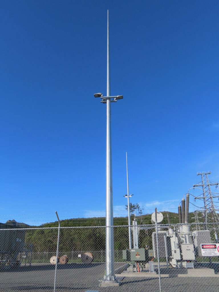
Image disclaimer: For identification and illustration only. It may show a product by another manufacturer and may not depict the exact item described; it is not a statement of any product’s quality, approval or performance. Third-party image and trademark rights belong to their owners. See full notice.
What Is It?
Lightning Protection for AGL systems is a holistic approach that encompasses both external (structural) and internal (electrical) protection measures. The system is designed to:
- Intercept direct lightning strikes via air terminals (lightning rods) installed on structures such as CCR buildings, control towers, and equipment shelters.
- Conduct the lightning current safely to ground using down conductors and earth termination systems.
- Prevent side‑flashing and sparking by ensuring proper bonding and equipotentialisation of all metallic parts.
- Protect sensitive AGL electronics (CCRs, ALCMS, LED drivers, communication systems) from induced surges and transient overvoltages caused by nearby lightning strikes.
- Ensure personal safety for maintenance personnel and airfield staff during lightning events.
A typical AGL lightning protection system includes air terminals, down conductors, earth electrodes, surge protection devices, and a comprehensive bonding network. The design follows international standards such as IEC 62305, NFPA 780, and FAA Advisory Circulars.
Purpose & Function
Lightning protection's purpose is to manage a threat that cannot be prevented — a direct or nearby lightning strike — by controlling where its energy goes and how much of it reaches sensitive AGL equipment, rather than leaving that outcome to chance. Air terminals and down conductors give a strike a preferred, engineered path to ground instead of an uncontrolled path through a building or piece of equipment, while the internal surge protection cascade absorbs and clamps the transient energy that still couples onto power and data lines even when the direct strike itself is safely diverted. Because a single lightning event can otherwise destroy CCRs, ALCMS electronics, and LED drivers across an entire airfield simultaneously, this layered external-and-internal approach exists to keep an isolated weather event from becoming a widespread, expensive equipment failure — or a hazard to personnel working nearby.
Where Is It Used?
Lightning protection is applied throughout the AGL infrastructure:
- CCR Rooms and Substations: Protecting the building structure, internal power distribution, and control equipment from direct strikes and surges.
- ALCMS and Communication Shelters: Protecting sensitive electronic racks, servers, and communication links.
- Lighting Control Panels (LCPs): Outdoor panels housing MCBs, contactors, and control relays require external and internal protection.
- Airfield Lighting Circuits: Series circuits (primary and secondary) are protected from induced surges through SPDs and proper earthing.
- Obstruction Lighting Structures: Towers, masts, and chimneys equipped with AGL obstruction lights must have dedicated lightning protection.
- Apron Floodlight Masts: Tall structures supporting floodlights and camera systems require air terminals and down conductors.
- Wind Cones and Sensor Masts: Meteorological equipment on exposed masts must be protected.
Installation & Location
Air terminals are mounted at the highest points of the structures they protect — rooftops of CCR rooms and shelters, the tops of obstruction masts, floodlight poles, and sensor masts — positioned and spaced according to the rolling-sphere or protection-angle method so the whole structure and any equipment on it falls within the protected zone. Down conductors are run by the shortest, most direct route from each air terminal to its earth termination, avoiding sharp bends, and are bonded to structural steelwork and metallic services along the way to prevent side-flashing. Surge protection devices are installed at the point cables enter a building or cabinet — main distribution boards, LCPs, and ALCMS racks — as close as practical to the incoming terminals, with the earth pit for the whole system positioned so the down-conductor and SPD earth paths bond back into the same low-resistance earthing network.
How Does It Work?
The lightning protection system operates through a combination of external and internal protection measures:
- External Lightning Protection:
- Air Terminals (Lightning Rods): Installed at the highest points of structures, they intercept the lightning strike and provide a preferential strike point.
- Down Conductors: Heavy‑gauge copper or aluminum conductors that carry the lightning current from the air terminal to the earth termination system.
- Earth Termination (Earthing): A network of earth electrodes (rods, plates, or grids) that dissipates the lightning current safely into the ground, preventing dangerous step and touch voltages.
- Bonding: All metallic parts (structural steel, cable trays, equipment enclosures) are bonded together to prevent side‑flashing and ensure equipotentialisation.
- Internal Lightning Protection (Surge Protection):
- SPD Cascade: A coordinated cascade of Surge Protection Devices (Type 1, Type 2, Type 3) is installed at the main distribution, sub‑distribution, and equipment levels to progressively reduce surge energy.
- Equipotential Bonding: All incoming services (power, data, telecom) are bonded to the main earthing terminal to prevent potential differences.
- Shielded Cables: Use of shielded cables for control and communication lines reduces the coupling of induced surges.
- Risk Assessment: The design is based on a risk assessment (following IEC 62305‑2) that evaluates the lightning strike frequency, exposure, and consequences to determine the required protection level (I–IV).
System Architecture & Control Logic
The lightning protection system is architecturally layered rather than centrally controlled: air terminals and down-conductors form a passive external network with no logic at all, while the internal surge protection is a coordinated cascade of SPDs (Type 1 at the main distribution board, Type 2 at sub-distribution, Type 3 at sensitive equipment) sized so that each stage progressively clamps and absorbs surge energy the previous stage let through, protecting the next device down the chain. There is no active decision-making in this cascade — each SPD simply conducts once its clamping voltage is exceeded — but many modern SPDs include a mechanical or electronic end-of-life indicator and a volt-free alarm contact, which can be wired back to a local panel, a building management system, or the ALCMS to report that a particular SPD stage has been exhausted by a surge event and needs replacement. Because the earth termination network underlies both the external and internal protection, its resistance is verified on the same testing schedule as the rest of the earthing system rather than monitored continuously.
Strike-to-Ground Energy Path
Direct Lightning Strike
Strikes the structure at its highest point
Air Terminal
Intercepts the strike, providing a preferential strike point
Down Conductor
Carries lightning current to earth (≥50mm² copper)
Earth Termination
Dissipates current into the ground, ≤10Ω resistance
Induced Transient Surge
Coupled onto power/data lines from a nearby strike
Type 1 SPD
Main distribution — absorbs bulk energy (10/350µs)
Type 2 SPD
Sub-distribution — reduces the residual surge (8/20µs)
Type 3 SPD
Equipment level — fine clamp for sensitive electronics
Equipment & Personnel Protected
A common bonding network ties both paths to the same earth reference, preventing side-flashing and dangerous potential differences.
Physical Construction
The system is built as a chain of physical elements rather than a single fixture: air terminals (copper, aluminium, or stainless-steel rods or meshed conductors) positioned at the highest points of a structure or mast to intercept a strike, down conductors of adequately sized copper or aluminium cable routed by the shortest practical path to ground, and earth electrodes — rods, plates, or ring earths — bonded at the base to dissipate the strike current into the soil. Down conductors are clipped or strapped to the structure with corrosion-resistant fixings, keeping a minimum isolation distance from other metalwork and cabling to avoid dangerous side-flashing, and bonding conductors tie every nearby metallic system (rails, ducting, cable armour) back to a common earthing busbar so no part of the installation sits at a different potential during a strike. Surge protection devices are fitted at points where power and data cabling enter equipment, housed in their own enclosures or DIN-rail modules within existing cabinets, and test links are built into the down-conductor run at ground level so the electrode resistance can be measured without disturbing the rest of the system.
Technical Parameters
| Parameter | Typical Value |
|---|---|
| Protection Level (IEC 62305) | Level I (highest) to Level IV (lowest), typically Level I for critical AGL infrastructure |
| Air Terminal Material | Copper (≥ 50mm², min. 8mm dia. round), Aluminium (≥ 70mm² tape), or Stainless Steel |
| Down Conductor Material | Copper (≥ 50mm²) or Aluminium (≥ 70mm² tape / 50mm² round) |
| Earth Electrode Resistance | ≤ 10Ω (typical), < 5Ω for critical systems |
| Earth Electrode Type | Copper‑bonded rods, copper plates, or ring earth electrodes |
| Surge Protection (SPD) | Type 1 (10/350 µs), Type 2 (8/20 µs), Type 3 (equipment) |
| Bonding Conductor | ≥ 16mm² copper, cross‑bonded to main earthing busbar |
| Isolation Distance | ≥ 1.5m (depending on protection level and conductor routing) |
| Inspection Interval | Annual visual inspection, full test every 2‑5 years |
| Standards Compliance | IEC 62305, NFPA 780, FAA AC 150/5340‑30, IS 2309 |
Applicable Standards
IEC 62305
Protection against lightning – Risk assessment, external protection, and internal surge protection
NFPA 780
Standard for the Installation of Lightning Protection Systems
FAA AC 150/5340‑30
Design and Installation Details for Airport Visual Aids — covers counterpoise/lightning protection and light‑base grounding
BS EN 62305
European standard for lightning protection (equivalent to IEC 62305)
Installation Requirements
Air Terminal Placement
MechanicalPosition and space air terminals at the highest points of the protected structure per the rolling-sphere or protection-angle method so the whole structure and any equipment on it falls within the protected zone.
Down Conductor Routing
ElectricalRun each down conductor by the shortest, most direct route from its air terminal to the earth termination, avoiding sharp bends.
Structural Bonding
ElectricalBond down conductors to structural steelwork and metallic services along the route to prevent side-flashing.
SPD Installation at Cable Entry
ElectricalInstall surge protection devices as close as practical to the incoming terminals at each building or cabinet entry point — main distribution boards, LCPs, and ALCMS racks.
Common Earth Network Bonding
ElectricalPosition the system earth pit so down-conductor and SPD earth paths bond back into the same low-resistance earthing network.
Isolation Distance Verification
DocumentationConfirm the isolation distance between down conductors and other services meets the requirement for the protection level installed.
Pre-Energisation Sign-off
DocumentationRecord air terminal positions, down-conductor routes, and SPD locations as-built before commissioning.
Testing & Commissioning
Earth Electrode Resistance Test
Pre-EnergisationMeasure the resistance of each earth electrode in the system using the fall-of-potential method, confirming the design target (typically ≤ 10Ω) is met before conductors are connected.
Down Conductor Continuity Test
Pre-EnergisationVerify continuity and resistance of each down conductor from air terminal to earth electrode, ruling out breaks or high-resistance joints before commissioning.
Bonding Conductor Continuity Test
EnergisationTest continuity of all bonding conductors to the main earthing busbar, confirming equipotential bonding is achieved across the protected structure.
Surge Protection Device (SPD) Function Test
EnergisationVerify each Type 1/2/3 SPD is correctly installed, rated for its location, and shows healthy status indication (where fitted) before the protected circuits are energised.
Isolation Distance Verification
Final AcceptanceConfirm the physical separation between lightning protection conductors and other services meets the calculated isolation distance for the system's protection level.
Air Terminal Placement & Zone of Protection Verification
Final AcceptanceSurvey air terminal positions against the design rolling-sphere or mesh method calculation, confirming the protected structure and equipment fall within the intended zone of protection.
Documentation & As-Built Sign-off
Final AcceptanceRecord electrode resistance, conductor continuity, SPD status, and isolation-distance verification alongside as-built terminal and conductor positions in the commissioning dossier for handover.
Inspection & Maintenance
Earth Resistance Test
AnnualMeasure earthing resistance and compare against the required threshold for the protection system.
Conductor & Connection Inspection
AnnualCheck down conductors and connections for corrosion or physical damage along their full run.
Bonding Continuity Check
AnnualVerify bonding continuity between metallic parts remains intact and within acceptable resistance.
SPD Status Check
QuarterlyCheck surge protection device end-of-life indicators and replace any that have tripped.
Post-Strike Inspection
After any recorded strikeInspect nearby AGL fixtures, conductors, and bonding points for damage following a lightning event.
Common Field Issues
Inadequate Earthing (High Resistance)
High earth resistance (> 10Ω) prevents effective dissipation of lightning current, leading to dangerous step voltages and equipment damage. Regular earthing testing and improvement (e.g., adding more rods, using chemical earthing) are essential.
Corrosion of Conductors and Connections
Copper and aluminium conductors are susceptible to corrosion, particularly in coastal or humid environments. Use of corrosion‑resistant materials, proper terminations, and regular inspection are critical.
Inadequate Bonding of Metallic Parts
Failure to bond all metallic parts (cable trays, equipment enclosures, structural steel) can result in side‑flashing and sparking, creating fire hazards and damaging sensitive electronics. Ensure comprehensive equipotential bonding.
SPD Degradation and End‑of‑Life
Surge Protection Devices have a limited lifespan and degrade with each surge event. Regular inspection of status indicators and timely replacement are essential to maintain protection.
Lightning Strike Damage to AGL Fixtures
Direct or nearby strikes can damage AGL fixtures, particularly those on elevated structures (runway edge lights, approach lights). Use of spark gaps, surge‑protected LED drivers, and proper earthing of fixture mounting hardware is recommended.
Troubleshooting Guide
Earth Resistance Test Exceeds 10Ω
Visible Corrosion on Down-Conductors or Terminations
Evidence of Sparking Between Metallic Parts
SPD Status Indicator Shows Fault or End-of-Life
AGL Fixture Damaged Following a Strike
Failure Modes & Root Causes
Elevated Earth Resistance
Down-Conductor or Termination Corrosion
Missing Equipotential Bonding
SPD End-of-Life
Fixture-Level Surge Protection Overwhelmed
Safety & Operational Notes
No Work on the System During a Storm
Personnel SafetySuspend all work on air terminals, down conductors, and earth termination points when an electrical storm is in the vicinity, and follow the aerodrome's lightning safety procedure until it has passed.
Assume Down Conductors May Carry Current
Electrical SafetyTreat down conductors and earth termination connections as potentially carrying lightning current at any time; do not disconnect a bonding link without confirming the disconnection is planned and the structure is not under active threat.
Work at Height on Air Terminals
Personnel SafetyUse appropriate fall protection when accessing rooftop or mast-mounted air terminals, and inspect mounting brackets and fixings for corrosion or looseness before relying on them to bear body weight or tools.
Test Before Relying on a Connection
Electrical SafetyMeasure earth resistance and continuity along the down-conductor path after any work, and do not treat a reinstated connection as effective protection until it has been tested.
Secure Bonding at Every Joint
ComplianceTorque bonding connections along the conductor run to the manufacturer's specification and protect each joint from corrosion, since a single loose or corroded joint can compromise the whole down-conductor path.
PPE & Continuity Testing
Personnel SafetyUse appropriate PPE and calibrated continuity/resistance test equipment when verifying the system, rather than a visual check alone, since a conductor can look intact while its electrical path is compromised.
FOD Control at Roof and Mast Work
OperationalKeep tools, fasteners, and fixings accounted for at all times when working at height on structures near the movement area, and secure or remove any loose material before leaving the area.
Restore to Compliant State
ComplianceDo not leave a system with a disconnected conductor, an out-of-tolerance resistance reading, or a corroded joint after maintenance; verify the measured values meet the design target before closing out the work.
Engineering & Expert Notes
Down Conductor Routing Matters as Much as Cross-Section
DesignA down conductor sized correctly on paper can still under-perform if it's routed with tight bends or run close to other services; lightning current follows the path of least inductance, and sharp bends or bundled cabling increase side-flash risk even when the conductor's rated capacity is adequate.
Equipotential Bonding Gaps Are the Usual Root Cause of Side-Flash Damage
BondingMost lightning-related equipment damage traces back to a metallic part that wasn't bonded into the equipotential system, not a failure of the air terminal or down conductor themselves; treat bonding continuity checks as core to the protection system, not a secondary item.
Earth Resistance Drifts Seasonally — Trend It, Don't Spot-Check
TestingSoil moisture and temperature can swing measured earth resistance significantly between wet and dry seasons; a single annual reading taken at the same time each year can mask a genuinely degrading earth system. Logging readings across seasons gives a far more reliable picture than one spot-check.
Surge Protection Devices Need Coordination, Not Just Installation
ElectricalInstalling an SPD at the incomer without coordinating let-through voltage and response time against downstream SPDs can leave sensitive electronics under-protected even though a device is technically present at every stage; verify the cascade is properly coordinated, not just populated.
Rolling Sphere Method Beats Guesswork for Air Terminal Placement
DesignAir terminal spacing set by eye or by copying a neighbouring structure's layout can leave unprotected zones on taller or irregular structures; applying the rolling sphere (or equivalent) method for the applicable protection level gives a defensible, repeatable placement rationale.
Corroded Earth Pit Connections Fail Silently Between Strikes
DurabilityAn earth pit connection can corrode to the point of high resistance without any visible external sign, and the fault only becomes apparent during an actual strike or the next scheduled continuity test; inspect and clean earth pit connections physically at overhaul rather than relying on resistance readings alone.
Frequently Asked Questions
Short answers about AGL lightning protection: air terminals, earthing, surge protection, standards and maintenance.
Q1What is lightning protection for AGL systems?
A holistic approach with external protection (air terminals intercepting strikes) and internal protection (earthing, bonding and surge protection) to protect structures and AGL equipment.
Q2Why is lightning protection needed?
A direct or nearby strike cannot be prevented, so the goal is to control where the energy goes and how much reaches sensitive AGL equipment instead of leaving it to chance.
Q3Where is lightning protection applied?
Throughout AGL infrastructure, including CCR rooms and substations and ALCMS and communication shelters.
Q4How does a lightning protection system work?
Air terminals at the highest points intercept the strike, down conductors carry the current to earth electrodes, and bonding and surge protective devices limit potential differences and surges inside the installation.
Q5What protection level is typical?
IEC 62305 defines Level I (highest) to Level IV (lowest), and Level I is typical for critical AGL infrastructure.
Q6What conductor and earthing specifications are typical?
Copper down conductors of at least 50 mm² (or 70 mm² aluminium tape), an earth electrode resistance of 10 ohms or less, and bonding conductors of at least 16 mm² copper cross-bonded to the main earthing busbar.
Q7What types of surge protection are used?
Type 1 (10/350 µs), Type 2 (8/20 µs) and Type 3 (equipment level) surge protective devices, coordinated to protect power and data entries.
Q8Which standards apply?
IEC 62305 and its European equivalent BS EN 62305, NFPA 780 and FAA AC 150/5340-30, which covers counterpoise and light-base grounding.
Q9How often should lightning protection be inspected?
Annually for earth resistance, conductor and connection condition and bonding continuity; quarterly for SPD end-of-life indicators; after any recorded strike; with a full test every 2-5 years.
Q10What if earth resistance exceeds 10 ohms?
Soil conditions, too few electrodes or corrosion may be responsible. Re-test using the fall-of-potential method and inspect the earthing system.
Related Components
Go Beyond the Component. Understand the Complete AGL System.
You have explored the component. Now understand how it works within the complete Airfield Ground Lighting system.
Learn AGL from fundamentals to design, installation, testing, photometry, commissioning, maintenance and troubleshooting through structured technical training at Precision AGL Academy.
Build practical knowledge. Understand the circuit. Read the standards. Troubleshoot with confidence.
Your next step in AGL starts here.
Need expert guidance on lightning protection design, testing, or upgrading?
Precision AGL Academy provides advice on risk assessment, earthing system design, SPD coordination, and compliance with international standards for AGL installations.
Follow the Academy
Important Notice, Disclaimer & Limitation of Liability
Please read before relying on any content on this page.
- Purpose and intended users. This page on Lightning Protection is an independent educational and informational reference for competent, suitably trained and authorised airfield ground lighting (AGL) and aerodrome electrical personnel. It is not professional engineering, legal or regulatory advice, and using it does not create any professional or client relationship.
- Safety. Work on series circuits, constant current regulators (CCRs), isolating transformers, cables, connectors and lighting equipment can be fatal. Always apply the aerodrome’s permit-to-work and isolation/LOTO procedures, prove dead, use correctly rated instruments and PPE, and follow the manufacturer’s instructions. Nothing here authorises work on live equipment or the bypassing of any safety device or interlock.
- Aviation operations. Nothing here authorises installation, modification, energisation, adjustment, return to service, a change of operating category (CAT I/II/III), a NOTAM or any aerodrome certification or approval decision. These rest with the aerodrome operator, the air navigation service provider and the competent regulator.
- Specifications, ratings and typical values. Descriptions, parameters, ratings, dimensions, photometric values, wattages, service lives, maintenance tasks and intervals, failure modes, certifications (for example CE, FCC, UL or IEC marks) and part or type designations are general, typical and indicative. They may not match any particular product, make, model or version, and they are not a datasheet, design, specification, selection, sizing, procurement or acceptance criterion. The manufacturer’s current documents, the approved design and the project specification prevail.
- Standards and regulations. References to ICAO, FAA, IEC, IEEE, ISO, BIS, DGCA and other standards are paraphrased summaries for orientation only. They may be incomplete or out of date, and standards are revised from time to time. Consult the current official editions. Following this content does not guarantee compliance with any law, standard or regulatory approval, and the regulator’s requirements always prevail.
- No warranty. Content is provided “as is” and “as available”, without warranty of any kind, express or implied, including accuracy, completeness, currency or fitness for a particular purpose. Real installations differ in design, equipment make and model, age and condition.
- Limitation of liability. To the fullest extent permitted by applicable law, Precision AGL Academy, Precision AGL Solutions and their owners, authors and contributors are not liable for any injury, death, loss, damage, downtime, penalty or regulatory consequence, whether direct or indirect, arising from the use of, reliance on, or inability to use this content. Nothing in this notice excludes or limits any liability that cannot lawfully be excluded or limited.
- Independence, brands and no endorsement. This is an independent publication. It is not affiliated with, sponsored by or endorsed by ICAO, the FAA, the IEC, DGCA, AAI, any airport, regulator, supplier or equipment manufacturer. Third-party names, product designations, standard designations and trademarks (including Megger®, Siemens, Eaton, Crouse-Hinds, ADB SAFEGATE, Fluke, ABB and Honeywell) belong to their respective owners and are used only for identification and description. Mention of a brand, product or supplier is not a recommendation, and we do not sell, supply or quote for any component described.
- Images and third-party content. Images and illustrations are shown to help identify the type of component. They may show products of various manufacturers, may not depict the exact item described, and are not a statement about any product’s quality, approval or performance. Copyright and trademarks in third-party images, logos and photographs belong to their respective owners and are not claimed as ours. If you are a rights holder and want an image removed, replaced or credited, email precisionaglsolutions@gmail.com with the page address and we will act promptly.
- Training and services. Mentions of training, courses, consultation, advice, selection, installation, calibration or other support, including the “Learn…Certify” pathway, describe learning stages and are not an offer, quotation, tender or promise of any result. Contacting us or our replying creates no engagement or duty of care; an engagement exists only under a written agreement. We are not a regulator or certification body, and completing any course or reading this content is not a certification, accreditation or authorisation to work on any aerodrome.
- Copyright, privacy and corrections. © 2026 Precision AGL Academy. All rights reserved. Text, structure, compilations and diagrams may be viewed for personal reference and internal training only; any other copying, republication or commercial use needs our written permission. If you email, telephone or message us, we use your details only to respond and handle your matter, in line with applicable Indian law including the Digital Personal Data Protection Act, 2023; please do not send confidential or security-sensitive information. To display this page your browser requests fonts, icons and images from third-party servers, which receive your IP address and browser details under their own policies. Content is reviewed periodically with no obligation to update. To report an error, safety concern or rights issue, write to precisionaglsolutions@gmail.com.