Mounting Ring
A precision‑machined, annular steel component that secures and aligns inset AGL light fixtures within the base can. It provides a robust, level mounting surface, ensures correct orientation of the light beam, and withstands heavy aircraft loads while allowing easy fixture removal for maintenance.
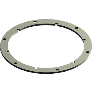
Image disclaimer: For identification and illustration only. It may show a product by another manufacturer and may not depict the exact item described; it is not a statement of any product’s quality, approval or performance. Third-party image and trademark rights belong to their owners. See full notice.
What Is It?
A Mounting Ring (also known as a fixture ring, retaining ring, or inset ring) is a heavy‑duty, annular steel component that is installed inside the base can to secure and align an inset (flush‑mounted) AGL light fixture. It provides the primary structural interface between the fixture and the base can, ensuring that the fixture is held firmly in place, is correctly orientated (both horizontally and vertically), and can be easily removed for maintenance or replacement.
Key characteristics of mounting rings include:
- Precision Machining: The ring is machined to tight tolerances to ensure accurate alignment of the fixture's optical axis with the required beam direction (e.g., towards the runway centreline).
- High Strength: Made from high‑grade steel (typically hot‑dip galvanised or stainless) to withstand the heavy aircraft wheel loads (rated ≥50–100 kN vertical) that are transmitted through the fixture.
- Corrosion Protection: Hot‑dip galvanised, powder‑coated, or stainless steel construction ensures long‑term resistance to the harsh airfield environment.
- Integrated Features: Often includes a tapered or stepped internal profile to guide the fixture into the correct position, and threaded holes or slots for the fixture's retaining bolts.
Mounting rings are used exclusively for inset (flush‑mounted) light fixtures, including:
- Runway Centreline Lights
- Touchdown Zone Lights (TDZ)
- Runway Edge Lights (inset versions)
- Taxiway Centreline Lights
- Stop Bars and Clearance Bars
- Threshold and End Lights (inset versions)
The ring is installed inside the base can (or directly into the pavement) and is secured with bolts or a locking mechanism. The fixture is then inserted into the ring and locked in place, often with a bayonet‑type or bolt‑down fixing.
Purpose & Function
An inset fixture has no pole to hold it steady — it sits flush in the pavement and takes the full weight of every aircraft wheel that rolls over it, so its mounting has to do two jobs that are easy to compromise against each other: hold the fixture rigidly enough to survive repeated heavy loading, and keep its optical axis aimed with enough precision that the beam still meets photometric requirements. The mounting ring's purpose is to carry that structural load through the base can and pavement rather than through the fixture's own housing or optics, so the fixture itself is protected from the forces it sits under. Just as importantly, because the ring's internal profile fixes the fixture's position and orientation every time it is inserted, a fixture removed for cleaning or lamp replacement goes back in correctly aligned without requiring re-aiming in the field — turning what could be a specialist realignment task into routine maintenance.
Where Is It Used?
Mounting rings are used wherever inset AGL fixtures are installed on paved surfaces, including:
- Runway Lighting: For inset runway centreline lights, touchdown zone lights, threshold lights, end lights, and edge lights (where flush mounting is required).
- Taxiway Lighting: For inset taxiway centreline lights, edge lights, stop bars, and clearance bars.
- Approach Lighting: For inset approach light fixtures and barrettes.
- Apron Lighting: For inset apron lighting and guidance systems.
The ring is typically installed in a base can that is embedded in the pavement, but in some cases, it can be installed directly into a prepared hole in the pavement using epoxy or mechanical anchors. The ring is designed to be flush with or slightly below the pavement surface to avoid interference with aircraft tyres and snowploughs.
Installation & Location
The ring is set into the pavement base can (or directly into a formed pavement pocket) so its top face sits exactly flush with the surrounding pavement surface, since a ring proud of or recessed below grade becomes either a FOD/tyre hazard or a water-pooling point. Ring position and level are checked against the pavement surface during setting-out, typically with a straightedge across the surrounding slab, before the fixture is bolted onto it; the ring's gasket or sealing face is inspected for pavement debris or old sealant before each re-fit so the fixture-to-ring seal isn't compromised by material trapped underneath.
How Does It Work?
The mounting ring functions as the primary alignment and retention device for the inset fixture. Its design ensures that the fixture is held securely, correctly orientated, and protected from the harsh pavement environment:
- Alignment: The ring's internal profile (often tapered or stepped) aligns the fixture as it is inserted, ensuring that the fixture's optical axis is precisely aligned with the required beam direction. This is critical for ensuring that the light beam meets the photometric requirements specified in ICAO and FAA standards.
- Retention: The ring provides threaded holes or slots for the fixture's retaining bolts. When the fixture is inserted, the bolts are tightened, securing the fixture firmly in the ring. This prevents the fixture from shifting or vibrating under aircraft loads.
- Load Transfer: The ring transfers the vertical loads from the aircraft tyres (through the fixture) directly to the base can and the surrounding pavement, distributing the load evenly and preventing localised stress.
- Accessibility: The ring allows the fixture to be easily removed for maintenance or replacement. Once the retaining bolts are loosened, the fixture can be lifted out of the ring without disturbing the base can or pavement.
The installation process typically involves:
- Cleaning: The base can interior and the mounting ring are cleaned and inspected for damage.
- Ring Placement: The mounting ring is placed inside the base can, aligning the bolt holes with the base can's threaded holes (or using separate anchor bolts).
- Levelling: The ring is levelled using shims or a levelling compound to ensure the top surface is perfectly horizontal.
- Securing: The ring is bolted into the base can using the specified torque.
- Fixture Installation: The fixture is inserted into the ring, orientated correctly, and secured with its retaining bolts.
The mounting ring is designed to provide a service life of 20+ years, with regular inspection for wear, corrosion, and bolt tightness.
The ring sits between fixture and pavement, carrying both alignment and load
Aircraft Tyre / Snowplough Load
Vertical load passes down through the flush-mounted fixture
Mounting Ring
- Alignment: tapered internal profile orients the optical axis on insertion
- Retention: threaded holes/slots secure the fixture's bolts against vibration
- Accessibility: bolts loosen for removal without disturbing the base can
Base Can & Surrounding Pavement
Load is distributed evenly outward, avoiding localised stress concentrations
Correctly Aimed, Securely Held, Serviceable
Photometric alignment holds under load, and the fixture lifts out cleanly for maintenance
System Architecture & Control Logic
The mounting ring is a mechanical alignment and retention component, not part of the electrical control chain — it sits in the base can or pavement recess and holds the inset fixture flush, correctly orientated, and secured against the loads of aircraft and vehicle traffic passing directly over it. Correct orientation matters because an inset fixture's beam pattern is fixed relative to its housing, so if the mounting ring lets the fixture rotate even slightly, the beam is no longer aimed where it needs to be even though the fixture itself and its circuit are functioning normally. Its condition — wear, looseness, corrosion — is assessed during physical inspection, since there is no signal path from the ring itself to the ALCMS.
Beam aim depends on this ring holding orientation — a fixture and circuit can be fully healthy and still aim wrong if it doesn't.
Physical Construction
The mounting ring is a machined annular collar of structural steel or stainless steel, hot-dip galvanised or passivated for corrosion resistance, sized so its outer diameter seats into the base can's internal bore while its inner diameter accepts and centres the fixture body. A bolt-hole pattern around the ring's face matches both the fixture base plate and the base can, clamping the two together and transferring vertical load through the ring into the can and surrounding pavement structure. The ring is machined to close tolerances on both diameters to hold the fixture's angular and horizontal alignment within the specified tolerance, since even small misalignment at this joint translates into beam-pointing error at the fixture. Gasket grooves or O-ring channels at the upper and lower faces maintain the assembly's overall IP67/IP68 seal, and the ring's corrosion-resistant finish is applied after machining to preserve its precise fit and load-bearing surfaces.
Technical Parameters
| Parameter | Typical Value |
|---|---|
| Material | Structural steel (S235JR or S355JR), hot‑dip galvanised (min 85µm) or stainless steel (316L) |
| Outer Diameter | 150mm to 300mm (6" to 12") – matches base can internal diameter |
| Inner Diameter | 100mm to 250mm – matches fixture outer diameter |
| Thickness | 10mm to 20mm |
| Surface Finish | Hot‑dip galvanised, powder‑coated, or stainless steel (plain or polished) |
| Bolt Hole Pattern | 4 or 6 holes (M8 to M16) – matches fixture and base can |
| Load Capacity (vertical) | ≥ 50 kN to 100 kN (depending on size and material) |
| Alignment Tolerance | ≤ 0.5° (angular) and ≤ 0.5mm (horizontal) |
| Corrosion Resistance | ≥ 500 hours salt spray (galvanised); ≥ 1000 hours (stainless) |
| Operating Temperature | -40°C to +85°C |
| Standards | FAA AC 150/5345‑42, ICAO Annex 14, EN 10025, ASTM A123 |
Applicable Standards
FAA AC 150/5345‑42
Specification for Airport Light Bases, Transformer Housings, Junction Boxes, and Accessories (includes mounting rings)
ICAO Annex 14
Physical characteristics of AGL mounting structures and fixtures
EN 10025
Hot‑rolled products of structural steels (material specification)
ASTM A123
Standard specification for zinc (hot‑dip galvanised) coatings on iron and steel products
Installation Requirements
Flush Level Setting
CivilSet the ring into the pavement base can or formed pocket so its top face sits exactly flush with the surrounding pavement, checked with a straightedge across the surrounding slab.
Sealing Face Inspection
MechanicalInspect the ring's gasket or sealing face for pavement debris or old sealant before each fit so the fixture-to-ring seal isn't compromised by trapped material.
Bolt Pattern Alignment
MechanicalConfirm the ring's bolt-hole pattern lines up with both the fixture base plate and the base can before clamping the assembly together.
Angular & Horizontal Tolerance Check
MechanicalVerify the ring holds the fixture within its specified angular and horizontal alignment tolerance, since even small misalignment at this joint translates into beam-pointing error.
Fitment Sign-off
DocumentationRecord ring level, bolt torque, and alignment as-built before the fixture is bolted on and accepted into service.
Testing & Commissioning
Optical Axis Alignment Check
Final AcceptanceInsert the fixture and confirm its optical axis aligns with the required beam direction, verified photometrically against ICAO/FAA tolerances.
Retaining Bolt Torque Verification
Final AcceptanceTorque retaining bolts to spec to secure the fixture against shifting or vibration under aircraft loads.
Level & Flush-Fit Check
Pre-InstallationConfirm the ring sits level and flush with the surrounding pavement so the inset fixture presents no trip or tyre-damage hazard.
Load Transfer Verification
Pre-InstallationConfirm the ring is correctly bedded to the base can and pavement so vertical loads transfer evenly without localised stress.
Ingress Protection Verification
Final AcceptanceConfirm the seal between the ring and base can meets its rated IP class before the surrounding pavement is finally reinstated.
Removability Check
Final AcceptanceConfirm the fixture can be lifted cleanly from the ring once bolts are loosened, verifying genuine access for future maintenance.
Documentation & As-Built Sign-off
Final AcceptanceRecord ring position, alignment verification, and torque values in the commissioning dossier for handover.
Inspection & Maintenance
Alignment Tolerance Check
AnnualVerify angular and horizontal alignment stay within the ≤0.5° / ≤0.5 mm tolerance so the fixture seats correctly against the base can.
Bolt Torque Verification
AnnualRe-torque mounting bolts to spec so the ring maintains its rated ≥50 kN vertical load capacity and stays properly seated.
Corrosion Check
AnnualInspect galvanised or stainless surfaces, especially the fixture-facing seat, for coating breakdown or pitting from trapped moisture.
Bolt Hole Pattern Verification
AnnualConfirm the bolt hole pattern remains true and undamaged, ensuring continued compatibility with the fixture and base can.
Seating Surface Wear Check
AnnualCheck the ring's inner and outer seating surfaces for wear or deformation that could affect fixture stability or the alignment tolerance.
Stack Stability Check
Semi-annualVerify there is no lateral play or rocking between the ring, fixture, and base can, which can develop after repeated freeze-thaw or traffic cycles.
Thickness / Deformation Check
AnnualInspect for cracking, dents, or thinning that could compromise the ring's load capacity under repeated vertical loading.
Standing Water Check
AnnualConfirm no water pools around the ring-to-base-can interface after rain, which can indicate a settling issue or blocked drainage.
Common Field Issues
Corrosion of Ring and Bolts
The mounting ring and its retaining bolts are exposed to moisture, de‑icing chemicals, and fuels. Galvanised coatings can be damaged during installation, leading to rust. Use stainless steel hardware and touch up damaged coatings. Regularly inspect and replace corroded bolts.
Loose Retaining Bolts
Vibration from aircraft can cause the fixture retaining bolts to loosen, resulting in fixture misalignment or movement. Use lock washers, thread‑locking compound, and schedule regular bolt torque checks as part of the maintenance program.
Wear of Ring Internal Profile
Repeated insertion and removal of the fixture can wear the internal alignment surfaces of the ring, reducing alignment accuracy. Inspect the ring for wear and replace if necessary. Apply a thin layer of anti‑seize or grease to the fixture's mating surfaces to reduce wear.
Incorrect Ring Height or Level
If the ring is not installed at the correct height or level, the fixture's beam pattern will be misaimed. Use shims and a precision level during installation, and verify the fixture's beam orientation after installation using a photometric test.
Debris Accumulation in Ring Grooves
Dirt, rubber deposits, and debris can accumulate in the ring's grooves and bolt holes, making it difficult to insert or remove the fixture. Regularly clean the ring with a wire brush and compressed air, and ensure the fixture's mating surfaces are clean.
Galvanic Corrosion Between Dissimilar Metals
If the mounting ring and the fixture are made of dissimilar metals (e.g., galvanised steel ring and aluminium fixture), galvanic corrosion can occur at the interface. Use a corrosion‑resistant coating, apply anti‑seize compound, or use a gasket to isolate the dissimilar metals.
Damaged Threads on Bolt Holes
The bolt holes in the ring or the fixture can become stripped, preventing secure fixing. Use thread inserts (Heli‑coils) to repair damaged threads, and apply anti‑seize compound to prevent galling.
Troubleshooting Guide
Rust Found on the Ring or Retaining Bolts
Fixture Misaligned or Loose Within the Ring
Fixture Alignment Accuracy Degrading Over Repeated Servicing
Fixture Beam Pattern Misaimed
Fixture Difficult to Insert or Remove
Corrosion Found at the Ring-to-Fixture Interface
Fixture Will Not Fasten Securely
Failure Modes & Root Causes
Retaining Bolt Fatigue Fracture
Ring Body Fatigue Cracking
Galvanic Corrosion at Ring-to-Fixture Interface
Internal Alignment Profile Wear
Protective Coating Breakdown
Bolt Hole Thread Stripping
Safety & Operational Notes
Series Circuit Isolation
Electrical SafetyDe-energise and lock out the circuit and verify zero energy before lifting the fixture out of the mounting ring or opening the base can beneath it.
Standing Water in the Base Can
Electrical SafetyTreat any water pooled around the mounting ring or in the can as potentially energised until isolation is confirmed, and drain before reaching in.
Correct Orientation on Reassembly
ComplianceSeat the fixture into the ring at the correct horizontal and vertical orientation before locking it in place, since an inset fixture installed off-orientation can present the wrong beam direction to approaching traffic.
Handling the Ring & Fixture
Personnel SafetyUse proper lifting technique for the heavy steel ring and fixture assembly to avoid strain injury or a dropped component in the base can.
Airside Work Coordination
OperationalCoordinate with ATC/airside and raise a NOTAM where the fixture will be dark during the work.
FOD Control
OperationalAccount for all fasteners and gaskets while the base can is open, and secure or remove loose material before reinstating the fixture.
Insulation Test Before Re-Energisation
Electrical SafetyMegger test the circuit after any connector or transformer work before restoring power, since a residual fault can trip the CCR or damage other fixtures on the same loop.
Engineering & Expert Notes
Ring Wear Accumulates Faster Than It Looks From a Quick Check
PrecisionRepeated fixture removal and reinsertion for maintenance gradually wears the precision-machined mating surfaces of a mounting ring; a ring that's seen many maintenance cycles can have looser tolerance than its visual condition suggests. Track cycle count or age, not just visual wear, when deciding on replacement.
Verify Ring Seating Before Blaming the Fixture for Misalignment
AlignmentA fixture reported as misaligned is sometimes actually a ring that's not fully and evenly seated in the base can; check ring seating first, since it's a faster fix than adjusting or replacing the fixture itself.
Inspect the Ring-to-Can Contact Surface for Debris Buildup
CorrosionDirt, sand, or corrosion product accumulating between the ring and the base can prevent full, even seating even when the ring itself is in good condition; clean this interface during routine fixture maintenance rather than only when a problem is already suspected.
Re-Torque Retaining Fasteners After the First Maintenance Cycle Post-Installation
MechanicalThe first time a ring's fixture is removed and reinserted after initial installation is a good checkpoint to verify retaining fasteners haven't loosened, since that removal cycle itself can reveal marginal torque that wasn't obvious at commissioning.
Frequent Maintenance Access Points Need More Frequent Seal Checks
DurabilityLocations with fixtures that are serviced often — due to known reliability issues or high-priority positions — see their mounting ring seals disturbed more frequently than the general array; weight seal inspection frequency accordingly rather than applying a uniform schedule.
Track Removal/Reinsertion Cycles for High-Maintenance Fixture Locations
DocumentationWhere a specific fixture location requires frequent removal for cleaning or replacement, logging the cycle count on the mounting ring helps anticipate wear-related replacement before it causes a loose or misaligned fixture.
Frequently Asked Questions
Short answers about mounting rings: function, alignment, loading, standards and maintenance.
Q1What is a mounting ring in airfield ground lighting?
A mounting ring, also called a fixture ring, retaining ring or inset ring, is a heavy-duty steel annular component installed inside the base can to secure and align an inset (flush-mounted) AGL fixture.
Q2What does a mounting ring do?
It aligns the fixture's optical axis with the required beam direction, retains the fixture with bolts against shifting and vibration, and transfers vertical aircraft tyre loads to the base can and surrounding pavement.
Q3Where are mounting rings used?
With inset runway centreline, touchdown zone, threshold and end lights, inset taxiway centreline and edge lights, stop bars and clearance bars, inset approach lights and inset apron lighting.
Q4What materials and loads do mounting rings handle?
Structural steel (S235JR or S355JR), hot-dip galvanised to at least 85 µm, or stainless steel, with a vertical load capacity of at least 50 kN to 100 kN depending on size and material.
Q5What is the alignment tolerance for a mounting ring?
The page gives 0.5° angular and 0.5 mm horizontal, checked annually so the fixture stays within its beam-alignment requirements.
Q6Which standards apply to mounting rings?
The main references are FAA AC 150/5345-42 (light bases, transformer housings, junction boxes and accessories), ICAO Annex 14, EN 10025 for the steel and ASTM A123 for galvanising.
Q7How often should mounting rings be inspected?
Annually. Verify alignment tolerance, re-torque the mounting bolts and inspect galvanised or stainless surfaces, especially the fixture-facing seat, for coating breakdown.
Q8What are the common problems with mounting rings?
Corrosion of the ring and bolts, loose retaining bolts from vibration, wear of the internal alignment profile from repeated fixture removal, and an incorrect ring height or level.
Related Components
Go Beyond the Component. Understand the Complete AGL System.
You have explored the component. Now understand how it works within the complete Airfield Ground Lighting system.
Learn AGL from fundamentals to design, installation, testing, photometry, commissioning, maintenance and troubleshooting through structured technical training at Precision AGL Academy.
Build practical knowledge. Understand the circuit. Read the standards. Troubleshoot with confidence.
Your next step in AGL starts here.
Need expert guidance on mounting ring selection and installation for your AGL project?
Precision AGL Academy provides advice on material selection, alignment techniques, corrosion prevention, and proper bolting for secure inset fixture mounting.
Follow the Academy
Important Notice, Disclaimer & Limitation of Liability
Please read before relying on any content on this page.
- Purpose and intended users. This page on Mounting Ring is an independent educational and informational reference for competent, suitably trained and authorised airfield ground lighting (AGL) and aerodrome electrical personnel. It is not professional engineering, legal or regulatory advice, and using it does not create any professional or client relationship.
- Safety. Work on series circuits, constant current regulators (CCRs), isolating transformers, cables, connectors and lighting equipment can be fatal. Always apply the aerodrome’s permit-to-work and isolation/LOTO procedures, prove dead, use correctly rated instruments and PPE, and follow the manufacturer’s instructions. Nothing here authorises work on live equipment or the bypassing of any safety device or interlock.
- Aviation operations. Nothing here authorises installation, modification, energisation, adjustment, return to service, a change of operating category (CAT I/II/III), a NOTAM or any aerodrome certification or approval decision. These rest with the aerodrome operator, the air navigation service provider and the competent regulator.
- Specifications, ratings and typical values. Descriptions, parameters, ratings, dimensions, photometric values, wattages, service lives, maintenance tasks and intervals, failure modes, certifications (for example CE, FCC, UL or IEC marks) and part or type designations are general, typical and indicative. They may not match any particular product, make, model or version, and they are not a datasheet, design, specification, selection, sizing, procurement or acceptance criterion. The manufacturer’s current documents, the approved design and the project specification prevail.
- Standards and regulations. References to ICAO, FAA, IEC, IEEE, ISO, BIS, DGCA and other standards are paraphrased summaries for orientation only. They may be incomplete or out of date, and standards are revised from time to time. Consult the current official editions. Following this content does not guarantee compliance with any law, standard or regulatory approval, and the regulator’s requirements always prevail.
- No warranty. Content is provided “as is” and “as available”, without warranty of any kind, express or implied, including accuracy, completeness, currency or fitness for a particular purpose. Real installations differ in design, equipment make and model, age and condition.
- Limitation of liability. To the fullest extent permitted by applicable law, Precision AGL Academy, Precision AGL Solutions and their owners, authors and contributors are not liable for any injury, death, loss, damage, downtime, penalty or regulatory consequence, whether direct or indirect, arising from the use of, reliance on, or inability to use this content. Nothing in this notice excludes or limits any liability that cannot lawfully be excluded or limited.
- Independence, brands and no endorsement. This is an independent publication. It is not affiliated with, sponsored by or endorsed by ICAO, the FAA, the IEC, DGCA, AAI, any airport, regulator, supplier or equipment manufacturer. Third-party names, product designations, standard designations and trademarks (including Megger®, Siemens, Eaton, Crouse-Hinds, ADB SAFEGATE, Fluke, ABB and Honeywell) belong to their respective owners and are used only for identification and description. Mention of a brand, product or supplier is not a recommendation, and we do not sell, supply or quote for any component described.
- Images and third-party content. Images and illustrations are shown to help identify the type of component. They may show products of various manufacturers, may not depict the exact item described, and are not a statement about any product’s quality, approval or performance. Copyright and trademarks in third-party images, logos and photographs belong to their respective owners and are not claimed as ours. If you are a rights holder and want an image removed, replaced or credited, email precisionaglsolutions@gmail.com with the page address and we will act promptly.
- Training and services. Mentions of training, courses, consultation, advice, selection, installation, calibration or other support, including the “Learn…Certify” pathway, describe learning stages and are not an offer, quotation, tender or promise of any result. Contacting us or our replying creates no engagement or duty of care; an engagement exists only under a written agreement. We are not a regulator or certification body, and completing any course or reading this content is not a certification, accreditation or authorisation to work on any aerodrome.
- Copyright, privacy and corrections. © 2026 Precision AGL Academy. All rights reserved. Text, structure, compilations and diagrams may be viewed for personal reference and internal training only; any other copying, republication or commercial use needs our written permission. If you email, telephone or message us, we use your details only to respond and handle your matter, in line with applicable Indian law including the Digital Personal Data Protection Act, 2023; please do not send confidential or security-sensitive information. To display this page your browser requests fonts, icons and images from third-party servers, which receive your IP address and browser details under their own policies. Content is reviewed periodically with no obligation to update. To report an error, safety concern or rights issue, write to precisionaglsolutions@gmail.com.