Network Redundancy Switch
A high‑availability industrial Ethernet switch that provides automatic failover and network redundancy for critical AGL communication links. Deployed in ring or dual‑homing topologies, the Network Redundancy Switch ensures uninterrupted data flow between the ALCMS, remote substations, and field equipment, even in the event of a cable break or switch failure, with recovery times as fast as 10‑50 ms.
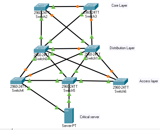
Image disclaimer: For identification and illustration only. It may show a product by another manufacturer and may not depict the exact item described; it is not a statement of any product’s quality, approval or performance. Third-party image and trademark rights belong to their owners. See full notice.
What Is It?
A Network Redundancy Switch (also known as a redundant Ethernet switch, high‑availability switch, or industrial redundancy switch) is a managed industrial Ethernet switch that incorporates advanced redundancy protocols to ensure uninterrupted network connectivity in the event of a link or device failure. In AGL applications, where communication between the ALCMS, CCRs, remote I/O, and field equipment is mission‑critical, network redundancy is essential to maintain control and monitoring capabilities during cable breaks, switch failures, or maintenance activities.
Key characteristics of the Network Redundancy Switch include:
- Redundancy Protocols: Supports industry‑standard redundancy protocols such as Ethernet Ring Protection Switching (ERPS, ITU‑T G.8032), Rapid Spanning Tree Protocol (RSTP), Multiple Spanning Tree Protocol (MSTP), Parallel Redundancy Protocol (PRP), and High‑availability Seamless Redundancy (HSR).
- Fast Failover: Provides sub‑second (typically 10‑50 ms) recovery time, ensuring minimal disruption to time‑sensitive control traffic.
- Ring Topology Support: Enables the construction of resilient ring networks with automatic loop detection and protection switching.
- Dual Homing: Supports dual‑homing connections to two separate switches or networks, providing redundant uplinks for critical nodes.
- Redundant Power Supplies: Includes dual, hot‑swappable power inputs (24 VDC) to eliminate single points of failure.
- Wide Operating Temperature: Industrial‑grade design for -40°C to +75°C operation, suitable for outdoor substations and equipment shelters.
- Comprehensive Management: Provides SNMP, web GUI, and CLI for configuration, monitoring, and diagnostics, including ring status, failover logs, and performance statistics.
In airfield lighting systems, the Network Redundancy Switch is deployed at critical aggregation points — such as the main control room, substations, and equipment shelters — to create a resilient fibre optic backbone. It ensures that a single cable cut or switch failure does not compromise AGL control and monitoring, supporting the high availability requirements of 24/7 airfield operations.
Purpose & Function
The redundancy switch exists because a single cable cut or switch failure should never be able to leave an operator unable to see or control part of the airfield lighting system — and on a live airfield, a backhoe strike, rodent damage, or a failed port is a matter of when, not if. Without redundancy protocols, that kind of routine failure would silently sever the ALCMS's connection to whatever equipment sat on the far side of it, and the operator might not even know they'd lost visibility until something else went visibly wrong. Sub-second failover is the specific number that matters here: it's fast enough that a brief link interruption resolves before it can cause a control action to be missed or a status update to go stale, effectively making the network as reliable as the fixtures it connects rather than a weak link beneath them.
Where Is It Used?
Network Redundancy Switches are deployed in all critical points of the AGL communication infrastructure where high availability is required. Key applications include:
- ALCMS Core Network: Providing redundant connectivity between the ALCMS server, workstations, and the airfield fibre backbone.
- CCR Substation Aggregation: Aggregating multiple CCR communication links and providing a redundant fibre uplink to the control room.
- Runway Edge Cabinet Rings: Creating resilient ring networks along the runway to connect edge cabinets, ensuring no single cable break isolates a segment.
- Approach Lighting Systems: Providing redundant Ethernet connectivity to approach light sequencers and flasher units.
- RWSL (Runway Status Light) System: Ensuring reliable, low‑latency communication between RWSL processing units and field controllers.
- Inter‑building Links: Providing redundant fibre connections between terminal buildings, ATC towers, and maintenance facilities.
- Critical Sensor Networks: Ensuring uninterrupted data from weather stations, visibility sensors, and RVR systems.
Installation & Location
Redundancy switches are mounted in 19-inch equipment racks or wall-mounted DIN-rail enclosures at each network aggregation point — the main control room, CCR substations, and field equipment shelters — rather than out in the open at individual fixtures. Fibre optic runs connect each switch to its neighbours around the ring, typically routed in dedicated ducting alongside but physically separate from the AGL power circuits to avoid electromagnetic interference and to keep a single trench excavation from risking both power and data continuity at once. Dual 24 VDC power inputs are fed from separate circuits or UPS-protected sources so a single power failure cannot take the switch down along with its data path, and the enclosure is selected for the ambient conditions of its location — sealed and temperature-rated for an unconditioned substation, standard rack-mount for a climate-controlled control room. Ring topology design means the physical cable route between switches is planned to avoid a single duct run or conduit carrying more than one segment of the same ring, so that one excavation or cable fault cannot break the ring in two places at once.
How Does It Work?
The Network Redundancy Switch operates by implementing redundancy protocols that automatically detect and recover from network failures. Key functional aspects include:
- Ring Protection (ERPS/RSTP): In a ring topology, the switch uses ERPS (G.8032) or RSTP to designate one switch as the "ring master" (for ERPS) or the root bridge (for RSTP). The protocol continuously monitors the ring integrity by sending and receiving health messages. If a link or switch fails, the protection mechanism re‑routes traffic around the ring, typically within 10‑50 ms (ERPS) or 1‑2 seconds (RSTP).
- Dual Homing / Link Aggregation: The switch supports multiple uplinks (e.g., two fibre links to different core switches) and can use Link Aggregation (LACP) or active‑standby failover. In the event of an uplink failure, traffic is automatically switched to the backup link.
- Redundant Power Inputs: The switch includes two independent power inputs (24 VDC) with diode‑or'ing or active load sharing. If one power supply fails, the other continues to power the switch without interruption.
- Fast Recovery Mechanisms: The switch monitors link status and protocol states, and upon detecting a failure, immediately updates the forwarding tables and re‑routes traffic. For ERPS, the recovery is triggered by the ring master, which sends a flush message to all switches to clear their MAC address tables and recompute the forwarding path.
- Diagnostics and Monitoring: The switch provides comprehensive monitoring of ring status, link state, power supply health, and traffic statistics via SNMP, web GUI, or CLI. Alarms (e.g., ring broken, power supply failure) can be sent to the ALCMS via SNMP traps or alarm contacts.
- Traffic Prioritization (QoS): To ensure that critical control traffic (e.g., PLC commands) is not delayed during failover, the switch supports IEEE 802.1p and DiffServ QoS, prioritising high‑priority frames.
The switch is typically configured via a web interface or command line, with redundancy settings tailored to the network topology (ring, dual‑homing, or hybrid). It is designed for hot‑swappable power supplies and fanless operation for high reliability.
Ring Failover & Control Logic
Ring Continuously Monitored
ERPS/RSTP health messages sent between switches
Physical Construction
The switch is built in a rugged extruded-aluminium or steel DIN-rail enclosure with a wide industrial temperature rating, using shielded RJ-45 connectors with integrated magnetics for the copper ports and soldered SFP cages for fibre uplinks, keeping copper and optical interfaces electrically isolated from one another. Internal electronics are conformally coated to resist dust, humidity, and airborne contaminants typical of unconditioned equipment cabinets, and the redundant 24 VDC power inputs terminate at screw-clamp terminals, with optional hot-swappable dual PSU modules available on higher-end models so a single power-path failure doesn't interrupt ring or chain communication. A dedicated alarm relay contact is brought out to a separate terminal so a ring break or switch fault can be wired directly into an external annunciator circuit independent of the network itself. The enclosure includes a chassis earth stud for bonding to the cabinet ground bus, and where deployed outside a conditioned cabinet, the unit is upgraded to a sealed field enclosure with cable glands for each cable entry point.
Technical Parameters
| Parameter | Typical Value |
|---|---|
| Number of Ports | 8, 16, 24 (copper 10/100/1000BASE‑T) + 2‑4 SFP (fiber) slots |
| SFP Support | 100BASE‑FX, 1000BASE‑SX/LX, 1000BASE‑ZX (copper or fiber SFP) |
| Redundancy Protocols | ERPS (G.8032), RSTP/MSTP, PRP, HSR (select models), LACP |
| Failover Time | < 50 ms (ERPS), < 2 sec (RSTP) |
| Ring Topology Support | Up to 254 nodes per ring (ERPS), flexible ring/chain/mesh |
| Switching Capacity | Up to 128 Gbps (non‑blocking) |
| Forwarding Rate | Up to 95 Mpps (for 24‑port Gigabit switch) |
| MAC Table Size | 8K‑32K entries |
| VLAN Support | IEEE 802.1Q VLAN (up to 4094 VLANs) |
| QoS | IEEE 802.1p, DiffServ (DSCP), 8 priority queues |
| Security Features | 802.1X (RADIUS), ACL, port security, SSH/HTTPS |
| Redundant Power Inputs | 2 x 24 VDC (18‑32 VDC), hot‑swappable (optional dual PSU modules) |
| Power Consumption | 15‑40 W (depending on port count and SFP load) |
| Operating Temperature | -40°C to +75°C (industrial grade) |
| Storage Temperature | -40°C to +85°C |
| Protection Class | IP30 (DIN‑rail mount), IP40 (ruggedized) |
| Mounting | DIN rail (EN 60715, 35mm) or rack mount (optional) |
| Diagnostics | Status LEDs (power, ring, link/activity), system log, SNMP traps, alarm relay contacts |
| Certifications | CE, FCC, UL, IEC 61000‑6‑2 (EMC immunity), IEC 61850 (substation), IEC 62443 (cybersecurity) |
Electrical Requirements
| Requirement | Typical Value |
|---|---|
| Circuit Type | Low-voltage DC auxiliary supply — network switch, not part of the airfield series circuit |
| Power Supply | 2 x 24VDC (18–32VDC), hot-swappable dual PSU (redundant) |
| Power Consumption | 15–40W depending on port count and SFP load |
| Cable Type | Cat5e/6 copper, fibre optic (SFP) |
| Earthing/Grounding | DIN-rail/rack chassis bonded to the cabinet earth bus |
| Fault Protection | Redundant PSU failover; alarm relay contacts on power/link loss |
| Standards | IEC 61000-6-2 (EMC immunity), IEC 62443 (cybersecurity) |
Applicable Standards
ITU‑T G.8032
Ethernet Ring Protection Switching (ERPS) — standard for sub‑50ms ring recovery
IEEE 802.1D/1w/1s
Spanning Tree Protocol (STP/RSTP/MSTP) — redundancy and loop prevention
IEC 61850
Communication networks for power utility automation (redundancy requirements)
FAA AC 150/5345‑56
Specification for AGL control and monitoring equipment (network redundancy)
Installation Requirements
Rack/DIN-Rail Mounting at Aggregation Point
MechanicalMount at the network aggregation point — control room, CCR substation, or field equipment shelter — rather than at individual fixtures.
Ring Fibre Routing
OpticalRoute fibre runs around the ring in dedicated ducting, physically separate from AGL power circuits to avoid electromagnetic interference and single-trench risk.
Dual Power Input Wiring
ElectricalFeed dual 24 VDC power inputs from separate sources before commissioning.
Redundancy Protocol Configuration
SoftwareConfigure the ring or redundancy protocol and VLAN/QoS settings before failover testing begins.
Pre-Commissioning Sign-off
DocumentationRecord mounting location, fibre routing, and protocol configuration as-built before ring failover testing.
Testing & Commissioning
Redundancy Protocol Configuration Check
Pre-EnergisationConfirm ring or redundancy protocol settings (e.g., RSTP, MRP) match the network topology drawing before the switch is commissioned.
Ring Failover Test
Final AcceptancePhysically break a network link and confirm traffic reroutes within the specified recovery time, then confirm restoration on reconnection.
Redundant Power Input Test
Pre-EnergisationConfirm the switch continues operating without interruption on loss of either power input.
VLAN & QoS Configuration Verification
Final AcceptanceConfirm VLAN segmentation and traffic-priority settings match the network design before handover.
SFP & Fibre Port Verification
InstallationMeasure optical power levels on fibre ports and confirm they fall within the link budget before connecting.
Documentation & As-Built Sign-off
Final AcceptanceRecord failover timing, VLAN configuration, and optical power readings in the commissioning dossier.
Inspection & Maintenance
Ring Failover Test
AnnualSimulate a link break to confirm ERPS/RSTP failover completes within the specified time and traffic reroutes without loops.
Redundant Power Input Test
Semi-annualRemove each 24 VDC input in turn to confirm the switch continues running on the remaining supply without a service interruption.
SFP & Fiber Port Inspection
AnnualClean fiber connectors and check optical power levels on SFP modules, since contamination is a common cause of degraded ring links.
VLAN & QoS Configuration Review
AnnualConfirm VLAN assignments and QoS priority queues still match the commissioned network design, especially after any device addition.
Security & Access Control Review
AnnualVerify 802.1X, ACLs, and port security settings remain correctly configured, and confirm SSH/HTTPS management access is current.
Terminal & Connector Tightness Check
AnnualRe-torque DIN-rail terminal and RJ-45 connections to spec, since loose terminations can cause intermittent link flapping.
Firmware & System Log Review
Semi-annualCheck for validated firmware updates and review the system log and SNMP traps for recurring link errors.
Status Indicator Function Test
QuarterlyConfirm power, ring, and link/activity LEDs respond correctly, and verify alarm relay contacts trip during a simulated fault.
Common Field Issues
Ring Misconfiguration
Incorrect ring port assignment, missing ring master configuration, or mismatched ring version (ERPS vs. RSTP) can prevent the ring from forming or cause loops. Always follow the manufacturer's configuration guidelines and verify ring status using the switch's management interface.
Failover Timeouts
If the failover time is too long (e.g., > 1 second), some time‑sensitive control protocols (e.g., Profinet IRT, EtherCAT) may time out. Use ERPS for sub‑50 ms failover and tune the watchdog timers to match the application's requirements.
Power Supply Failure
Even with dual power inputs, a failure of both supplies or a common upstream power issue can cause the switch to lose power. Ensure that each power input is fed from a separate, independent power source (e.g., different UPS units) to achieve true redundancy.
Firmware Incompatibility
Mixing switches from different vendors or different firmware versions on the same ring can cause interoperability issues with redundancy protocols. Use switches from the same family and maintain consistent firmware versions across the ring.
Physical Cable Damage
While redundancy protects against single failures, multiple cable breaks or a cut at a common point (e.g., a trench) can still cause network segmentation. Design the ring to route cables via diverse physical paths where possible.
Traffic Flooding During Failover
During failover, the switch may flush its MAC address table, causing a temporary flood of unknown unicast frames. This can increase network load. Use rapid failover protocols and ensure the network has sufficient bandwidth headroom to handle the flood.
Alarm Suppression
In a ring, a single failure can trigger alarms from multiple switches (e.g., link‑down on both ends). Configure alarm suppression to avoid flooding the ALCMS with redundant alarms. Many switches support a "ring alarm" that only triggers when the entire ring is broken.
Troubleshooting Guide
Ring Fails to Form or Network Loop Detected
Time-Sensitive Control Protocol Drops Out During Failover
Switch Loses Power Despite Dual Power Inputs
Redundancy Protocol Unstable in a Mixed-Vendor Ring
Network Segmentation Despite Ring Redundancy
Network Congestion Immediately After a Failover Event
ALCMS Flooded With Alarms From a Single Ring Fault
Failure Modes & Root Causes
Ring Misconfiguration
Failover Timeout
Power Supply Failure (One of Dual Inputs)
Firmware Incompatibility in a Mixed-Vendor Ring
Physical Cable / SFP Damage
Traffic Flooding During Failover
Safety & Operational Notes
Isolate One Power Input Before Internal Work
Electrical SafetyWith dual power inputs, de-energise and lock out both supplies before opening the switch for internal work; assuming the switch is dead because one input is off is a common miscue on redundant-power equipment.
Verify Ring Configuration Before Going Live
VerificationConfirm the redundancy protocol, ring ID, and port roles are correctly set after commissioning or any change; a misconfiguration can prevent the ring from forming or create a network loop that brings down the whole ring rather than just one segment.
Test Actual Failover Time
VerificationRun a ring failover test and measure the actual convergence time against the requirement for the time-sensitive control protocols riding the ring, since a default setting that is too slow can drop control traffic during failover even though the ring eventually recovers.
Confirm Redundancy Restored Before Closing Out
OperationalAfter any port or cabling change, confirm the ring has healed and full redundancy is restored, rather than just confirming the network is currently passing traffic on the primary path.
ESD Precautions
Electrical SafetyUse anti-static handling precautions when servicing the switch or its modules, since electrostatic discharge can damage switching electronics with no immediate outward sign of failure.
PPE & Grounding
Personnel SafetyConfirm the switch enclosure is bonded/grounded per the electrical design, and use standard PPE appropriate to the panel it is mounted in.
Confirm Fallback Before Taking a Unit Down
OperationalVerify the ring or redundant path can carry the traffic before removing a switch for service, since this device is specifically relied upon to keep ALCMS/CCR communication alive during a link or device failure.
Restore to Compliant State
ComplianceConfirm both power inputs are live, the ring is fully formed, and a failover test passes before closing out the work.
Engineering & Expert Notes
Mixed Redundancy Protocols on One Ring Rarely Interoperate Cleanly
DesignCombining switches configured for different redundancy protocols, or even different vendors' implementations of the same protocol, on a single ring often works fine under normal conditions but produces unpredictable recovery behaviour during an actual fault. Standardise protocol and, where possible, vendor within a given ring rather than mixing to save cost on one segment.
Verify Failover Time Under Real Load, Not Just at Idle
TestingA ring that recovers in the advertised sub-50ms window during a quiet acceptance test can take noticeably longer under the traffic load of a busy operational network with many active nodes. Test failover timing under realistic traffic conditions, since that's the scenario the redundancy actually needs to perform in.
Redundant Ring Cabling Needs Physical Path Diversity, Not Just Logical Redundancy
InstallationA ring topology only protects against a single break if the two paths around the ring are actually routed through physically separate ducts or trenches; a ring where both halves happen to run through the same conduit for part of the route offers far less real protection than the topology diagram suggests.
Repeated Micro-Failovers Are a Symptom, Not Background Noise
TroubleshootingA ring that shows frequent brief failover events, each individually too short to cause a noticeable outage, is often an early sign of an intermittent connector, a marginal fibre splice, or EMI on one segment; log and trend failover event frequency rather than dismissing sub-second events as inconsequential.
Managed Switch Access Deserves the Same Hardening as Any Other Critical Node
CybersecurityThe switches carrying control and monitoring traffic for the entire AGL network are themselves a high-value target if compromised; disable unused management interfaces, change default credentials, and keep firmware current on redundancy switches with the same discipline applied to the PLC or SCADA interface.
Document Ring Topology Changes as They Happen, Not at the Next Audit
DocumentationA ring modified during a field project to add a new node or reroute a segment, without a corresponding update to the network diagram, leaves the next person troubleshooting a fault working from an inaccurate picture of the actual topology. Update topology documentation at the time of the change.
Frequently Asked Questions
Short answers about the Network Redundancy Switch: what it is, how it works, typical specifications, standards, maintenance and common faults.
Q1What is a Network Redundancy Switch?
A Network Redundancy Switch (also known as a redundant Ethernet switch, high‑availability switch, or industrial redundancy switch) is a managed industrial Ethernet switch that incorporates advanced redundancy protocols to ensure uninterrupted network connectivity in the event of a link or device failure. In AGL applications, where communication between the ALCMS, CCRs, remote I/O, and field equipment is mission‑critical, network redundancy is essential to maintain control and monitoring capabilities during cable breaks, switch failures, or maintenance activities.
Q2What is the purpose of a Network Redundancy Switch?
The redundancy switch exists because a single cable cut or switch failure should never be able to leave an operator unable to see or control part of the airfield lighting system — and on a live airfield, a backhoe strike, rodent damage, or a failed port is a matter of when, not if.
Q3Where is a Network Redundancy Switch used and installed?
Network Redundancy Switches are deployed in all critical points of the AGL communication infrastructure where high availability is required. Key applications include: ALCMS Core Network: Providing redundant connectivity between the ALCMS server, workstations, and the airfield fibre backbone. CCR Substation Aggregation: Aggregating multiple CCR communication links and providing a redundant fibre uplink to the control room. Runway Edge Cabinet Rings: Creating resilient ring networks along the runway to connect edge cabinets, ensuring no single cable break isolates a segment.
Q4How does a Network Redundancy Switch work?
The Network Redundancy Switch operates by implementing redundancy protocols that automatically detect and recover from network failures. Key functional aspects include: Ring Protection (ERPS/RSTP): In a ring topology, the switch uses ERPS (G.8032) or RSTP to designate one switch as the "ring master" (for ERPS) or the root bridge (for RSTP). The protocol continuously monitors the ring integrity by sending and receiving health messages.
Q5What are the typical technical parameters of a Network Redundancy Switch?
Typical values are — Number of Ports: 8, 16, 24 (copper 10/100/1000BASE‑T) + 2‑4 SFP (fiber) slots; SFP Support: 100BASE‑FX, 1000BASE‑SX/LX, 1000BASE‑ZX (copper or fiber SFP); Redundancy Protocols: ERPS (G.8032), RSTP/MSTP, PRP, HSR (select models), LACP; Failover Time: < 50 ms (ERPS), < 2 sec (RSTP); Ring Topology Support: Up to 254 nodes per ring (ERPS), flexible ring/chain/mesh; Switching Capacity: Up to 128 Gbps (non‑blocking); Forwarding Rate: Up to 95 Mpps (for 24‑port Gigabit switch); MAC Table Size: 8K‑32K entries; VLAN Support: IEEE 802.1Q VLAN (up to 4094 VLANs); QoS: IEEE 802.1p, DiffServ (DSCP), 8 priority queues.
Q6What are the electrical requirements for a Network Redundancy Switch?
Typical requirements are — Circuit Type: Low-voltage DC auxiliary supply — network switch, not part of the airfield series circuit; Power Supply: 2 x 24VDC (18–32VDC), hot-swappable dual PSU (redundant); Power Consumption: 15–40W depending on port count and SFP load; Cable Type: Cat5e/6 copper, fibre optic (SFP); Earthing/Grounding: DIN-rail/rack chassis bonded to the cabinet earth bus; Fault Protection: Redundant PSU failover; alarm relay contacts on power/link loss; Standards: IEC 61000-6-2 (EMC immunity), IEC 62443 (cybersecurity).
Q7Which standards apply to a Network Redundancy Switch?
The main references are ITU‑T G.8032 — Ethernet Ring Protection Switching (ERPS) — standard for sub‑50ms ring recovery; IEEE 802.1D/1w/1s — Spanning Tree Protocol (STP/RSTP/MSTP) — redundancy and loop prevention; IEC 61850 — Communication networks for power utility automation (redundancy requirements); FAA AC 150/5345‑56 — Specification for AGL control and monitoring equipment (network redundancy). Always verify the current edition and your aerodrome's approved requirements.
Q8How often should a Network Redundancy Switch be inspected and maintained?
Typical maintenance tasks and intervals are: Ring Failover Test (annual); Redundant Power Input Test (semi-annual); SFP & Fiber Port Inspection (annual); VLAN & QoS Configuration Review (annual); Security & Access Control Review (annual); Terminal & Connector Tightness Check (annual); Firmware & System Log Review (semi-annual); Status Indicator Function Test (quarterly). Your airport's approved maintenance programme takes precedence.
Q9How do I troubleshoot common Network Redundancy Switch faults?
Common symptoms covered are: Ring Fails to Form or Network Loop Detected; Time-Sensitive Control Protocol Drops Out During Failover; Switch Loses Power Despite Dual Power Inputs; Redundancy Protocol Unstable in a Mixed-Vendor Ring; Network Segmentation Despite Ring Redundancy; Network Congestion Immediately After a Failover Event; ALCMS Flooded With Alarms From a Single Ring Fault. For example, for "Ring Fails to Form or Network Loop Detected": Likely Cause: Incorrect ring port assignment, missing ring master configuration, or mismatched ring protocol (ERPS vs. RSTP) between switches. Diagnostic Steps: Check ring status and port role on the switch's management interface; verify ring master and port configuration against the manufacturer's guidelines on every switch in the ring. Corrective Action: Correct the ring port assignment and protocol configuration to match across all switches, and re-verify ring status shows a healthy, closed ring.
Related Components
Go Beyond the Component. Understand the Complete AGL System.
You have explored the component. Now understand how it works within the complete Airfield Ground Lighting system.
Learn AGL from fundamentals to design, installation, testing, photometry, commissioning, maintenance and troubleshooting through structured technical training at Precision AGL Academy.
Build practical knowledge. Understand the circuit. Read the standards. Troubleshoot with confidence.
Your next step in AGL starts here.
Need expert guidance on Network Redundancy Switch selection, ring design, or failover configuration for your AGL network?
Precision AGL Academy provides advice on redundancy protocols, topology design, failover tuning, and best practices for resilient AGL communication infrastructure.
Follow the Academy
Important Notice, Disclaimer & Limitation of Liability
Please read before relying on any content on this page.
- Purpose and intended users. This page on Network Redundancy Switch is an independent educational and informational reference for competent, suitably trained and authorised airfield ground lighting (AGL) and aerodrome electrical personnel. It is not professional engineering, legal or regulatory advice, and using it does not create any professional or client relationship.
- Safety. Work on series circuits, constant current regulators (CCRs), isolating transformers, cables, connectors and lighting equipment can be fatal. Always apply the aerodrome’s permit-to-work and isolation/LOTO procedures, prove dead, use correctly rated instruments and PPE, and follow the manufacturer’s instructions. Nothing here authorises work on live equipment or the bypassing of any safety device or interlock.
- Aviation operations. Nothing here authorises installation, modification, energisation, adjustment, return to service, a change of operating category (CAT I/II/III), a NOTAM or any aerodrome certification or approval decision. These rest with the aerodrome operator, the air navigation service provider and the competent regulator.
- Specifications, ratings and typical values. Descriptions, parameters, ratings, dimensions, photometric values, wattages, service lives, maintenance tasks and intervals, failure modes, certifications (for example CE, FCC, UL or IEC marks) and part or type designations are general, typical and indicative. They may not match any particular product, make, model or version, and they are not a datasheet, design, specification, selection, sizing, procurement or acceptance criterion. The manufacturer’s current documents, the approved design and the project specification prevail.
- Standards and regulations. References to ICAO, FAA, IEC, IEEE, ISO, BIS, DGCA and other standards are paraphrased summaries for orientation only. They may be incomplete or out of date, and standards are revised from time to time. Consult the current official editions. Following this content does not guarantee compliance with any law, standard or regulatory approval, and the regulator’s requirements always prevail.
- No warranty. Content is provided “as is” and “as available”, without warranty of any kind, express or implied, including accuracy, completeness, currency or fitness for a particular purpose. Real installations differ in design, equipment make and model, age and condition.
- Limitation of liability. To the fullest extent permitted by applicable law, Precision AGL Academy, Precision AGL Solutions and their owners, authors and contributors are not liable for any injury, death, loss, damage, downtime, penalty or regulatory consequence, whether direct or indirect, arising from the use of, reliance on, or inability to use this content. Nothing in this notice excludes or limits any liability that cannot lawfully be excluded or limited.
- Independence, brands and no endorsement. This is an independent publication. It is not affiliated with, sponsored by or endorsed by ICAO, the FAA, the IEC, DGCA, AAI, any airport, regulator, supplier or equipment manufacturer. Third-party names, product designations, standard designations and trademarks (including Megger®, Siemens, Eaton, Crouse-Hinds, ADB SAFEGATE, Fluke, ABB and Honeywell) belong to their respective owners and are used only for identification and description. Mention of a brand, product or supplier is not a recommendation, and we do not sell, supply or quote for any component described.
- Images and third-party content. Images and illustrations are shown to help identify the type of component. They may show products of various manufacturers, may not depict the exact item described, and are not a statement about any product’s quality, approval or performance. Copyright and trademarks in third-party images, logos and photographs belong to their respective owners and are not claimed as ours. If you are a rights holder and want an image removed, replaced or credited, email precisionaglsolutions@gmail.com with the page address and we will act promptly.
- Training and services. Mentions of training, courses, consultation, advice, selection, installation, calibration or other support, including the “Learn…Certify” pathway, describe learning stages and are not an offer, quotation, tender or promise of any result. Contacting us or our replying creates no engagement or duty of care; an engagement exists only under a written agreement. We are not a regulator or certification body, and completing any course or reading this content is not a certification, accreditation or authorisation to work on any aerodrome.
- Copyright, privacy and corrections. © 2026 Precision AGL Academy. All rights reserved. Text, structure, compilations and diagrams may be viewed for personal reference and internal training only; any other copying, republication or commercial use needs our written permission. If you email, telephone or message us, we use your details only to respond and handle your matter, in line with applicable Indian law including the Digital Personal Data Protection Act, 2023; please do not send confidential or security-sensitive information. To display this page your browser requests fonts, icons and images from third-party servers, which receive your IP address and browser details under their own policies. Content is reviewed periodically with no obligation to update. To report an error, safety concern or rights issue, write to precisionaglsolutions@gmail.com.