Remote Diagnostics Module
A powerful software and hardware platform that enables remote troubleshooting, predictive maintenance, and real-time system health monitoring for AGL installations. This module drastically reduces operational downtime, eliminates unnecessary site visits, and provides deep insights into airfield lighting system performance.
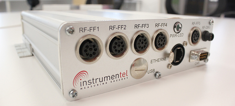
Image disclaimer: For identification and illustration only. It may show a product by another manufacturer and may not depict the exact item described; it is not a statement of any product’s quality, approval or performance. Third-party image and trademark rights belong to their owners. See full notice.
What Is It?
A Remote Diagnostics Module is an advanced software platform (often integrated with hardware appliances) that connects to AGL equipment—including Constant Current Regulators (CCRs), smart fixtures, isolating transformers, and sensors—to provide comprehensive remote visibility. It enables:
- Real-time performance monitoring of all connected AGL devices
- Automated fault detection and predictive analytics to foresee failures
- Secure remote access for troubleshooting and firmware updates
- Centralized data logging and reporting for compliance and trend analysis
- Integration with ALCMS and enterprise cloud platforms
By shifting from reactive to proactive maintenance, the Remote Diagnostics Module helps airports maximize uptime, extend equipment life, and optimize maintenance budgets.
Purpose & Function
The remote diagnostics module's purpose is to let engineers understand and often resolve a problem with AGL equipment without first sending a technician to the field, collapsing what could be a multi-hour dispatch-and-diagnose cycle into a remote check that can happen the moment an alert fires. Because it aggregates real-time status from CCRs, smart fixtures, transformers, and sensors into a single view, it lets an operations team see the health of the entire lighting system at once rather than piecing together isolated fault reports, and its secure remote-access capability means a firmware update or configuration fix that would otherwise require a site visit can often be applied immediately. This combination of visibility and remote intervention is what turns airfield maintenance from a purely reactive, on-site activity into one that can be triaged and, in many cases, resolved centrally.
Where Is It Used?
The Remote Diagnostics Module is deployed in various operational and maintenance contexts across the airfield:
- Airport Operations Centers: Providing a unified dashboard for monitoring the health of all AGL systems.
- Maintenance Control Rooms: Enabling technicians to diagnose and resolve issues without dispatching to the field.
- Cloud-Based Monitoring: Aggregating data from multiple airports for centralized fleet management.
- Integration with ATC: Ensuring that air traffic controllers have real-time awareness of lighting system status.
- Vendor Remote Support: Allowing OEMs to securely access systems for advanced diagnostics and software updates.
It is a core component of any modern Smart Airport or digital airfield strategy.
Installation & Location
The module is mounted inside the CCR cabinet, control room rack, or field equipment enclosure it serves, close to the devices it polls so local wiring (RS-485, Modbus, or a hardwired I/O loom) stays short and shielded from the high-current circuits nearby. Network connectivity, whether fibre, Ethernet, or a cellular/radio uplink, is terminated and tested at installation, with the module sited so its antenna or fibre patch has a clear, direct route out of the enclosure. Power is taken from the host cabinet's control supply, ideally backed by the same UPS protecting the equipment it monitors, so diagnostics remain available through a mains outage, and the unit is registered on the ALCMS or central monitoring platform as part of commissioning rather than left running in isolation.
How Does It Work?
The Remote Diagnostics Module works by establishing a secure, bidirectional communication link between the AGL equipment and the diagnostic platform. The process involves:
- Data Acquisition: Collecting telemetry data from field devices via IoT Gateways or directly through secure network tunnels.
- Data Processing: Normalizing and analyzing the data using rule-based engines and machine learning algorithms to detect anomalies.
- Visualization: Presenting system health, alerts, and trends through intuitive dashboards and reporting tools.
- Remote Intervention: Enabling secure remote commands for firmware updates, parameter adjustments, and advanced testing procedures.
- Cybersecurity: Utilizing end-to-end encryption, multi-factor authentication, and role-based access control to ensure secure access.
This continuous feedback loop ensures that potential issues are identified and resolved before they escalate into critical failures.
System Architecture & Control Logic
The module sits above the field control layer, aggregating telemetry from IoT gateways, smart fixtures and transformers, and PLCs rather than issuing real-time lighting commands itself. Its control authority is limited to supervisory actions — parameter changes, firmware pushes, diagnostic test triggers — which are logged and require authenticated, role-based access; the actual switching and intensity commands to CCRs and lighting loops remain with the ALCMS. This separation is deliberate: a fault or security compromise in the diagnostics module cannot directly alter runway or taxiway lighting state, since it has no write path into loop-level control, only into the visibility and remote-maintenance functions layered on top of it.
The Bidirectional Diagnostic Loop
Field Devices
CCRs, smart fixtures, transformers, sensors
Data Acquisition
Telemetry via IoT Gateway or secure network tunnel
Data Processing
Rule-based & ML anomaly detection
Visualization
Dashboards, alerts & trend reports
Ops Center Decision
Technician reviews alert, initiates action
Remote Command
Firmware update, parameter change, test trigger
Field Devices
Updated & verified without a site visit
Physical Construction
Since the module is a software platform "often integrated with hardware appliances," its physical form depends on how it's deployed: as a rack-mounted server appliance in an equipment shelter or ALCMS server room (indoor rated, IP40) with local SSD storage (1TB+) and redundant power via 24V DC, PoE+, or dual AC feeds, or as a hardened outdoor unit (IP65) at the field edge where connectivity to CCRs and smart fixtures is more direct. Where it does run as physical hardware, the enclosure carries the same secure-element/TPM-anchored construction as other AGL network appliances, keeping the TLS and VPN cryptographic keys in tamper-resistant hardware rather than in software alone. Where it runs as a pure software layer on shared infrastructure instead, its "construction" is the same redundant, multi-node server and storage architecture that underlies any AGL cloud service.
Technical Parameters
| Parameter | Typical Value |
|---|---|
| Communication Protocols | Modbus TCP/RTU, SNMP, MQTT, HTTPS, WebSocket |
| Supported Hardware | CCRs, Smart Fixtures, Transformers, PLCs, Sensors |
| Diagnostic Capabilities | Firmware OTA, Log Retrieval, Performance Tests, Trend Analysis |
| Cybersecurity | TLS 1.3, IPsec VPN, X.509 Auth, RBAC, Audit Logging |
| Alert Mechanisms | Email, SMS, SNMP Traps, Push Notifications, Webhooks |
| Data Storage | Local SSD (1TB+) with cloud synchronization |
| Power Supply (Hardware) | 24V DC, PoE+ (IEEE 802.3at), or redundant AC |
| Environmental Rating | IP40 (indoor) to IP65 (hardened outdoor models) |
| Operating Temperature | -20°C to +60°C |
| Standards Compliance | ISO 27001, NIST CSF, IEC 62443, GDPR |
Electrical Requirements
| Requirement | Typical Value |
|---|---|
| Power Input | 24V DC, PoE+ (IEEE 802.3at), or redundant AC feed |
| Circuit Type | Independent low-voltage/network power, separate from the series lighting circuits it monitors |
| Backup Power | Redundant AC input or UPS-backed supply recommended for continuous monitoring uptime |
| Cable Type | Shielded Ethernet (Cat5e/6) for PoE+, or standard low-voltage DC power cable |
| Earthing/Grounding | Enclosure and rack bonded to local earth/equipment ground |
| Surge Protection | Surge suppression on power and network inputs at cabinet entry |
| Fault Protection | Overcurrent and reverse-polarity protection on DC input; PoE+ negotiation per IEEE 802.3at |
Applicable Standards
ISO 27001
Information security management for data protection
NIST Cybersecurity Framework
Critical infrastructure cybersecurity best practices
IEC 62443
Security for industrial automation and control systems
FAA AC 150/5345‑56
Specification for L‑890 Airport Lighting Control and Monitoring System (ALCMS integration)
Installation Requirements
Enclosure Mounting & Clearance
MechanicalMount the module inside the CCR cabinet, control room rack, or field enclosure it serves, with clearance for ventilation and cable access.
Field Bus Wiring
ElectricalTerminate RS-485, Modbus, or hardwired I/O looms as short runs, shielded and routed clear of adjacent high-current circuits.
Network Uplink Termination
NetworkTerminate and test the fibre, Ethernet, or cellular/radio uplink, siting the module so its antenna or fibre patch has a clear, direct route out of the enclosure.
Power & UPS Backup
ElectricalTake power from the host cabinet's control supply, ideally backed by the same UPS protecting the equipment the module monitors.
Device Polling List Configuration
SoftwareConfigure the module's polling list and device addresses for the CCRs and field devices it will monitor before commissioning tests begin.
Pre-Commissioning Sign-off
DocumentationRecord installation location, wiring terminations, and network configuration as-built before handover to commissioning.
Testing & Commissioning
Network Connectivity & Secure Tunnel Test
Pre-CommissioningConfirm a secure connection can be established between the field devices and the diagnostic platform via the IoT Gateway or network tunnel.
Authentication & Access Control Verification
Functional TestConfirm multi-factor authentication and role-based access control correctly restrict access to authorised users only.
Data Acquisition Accuracy Test
Functional TestCompare telemetry values received by the platform against known reference readings from the field device.
Anomaly Detection Rule Validation
Functional TestInject test conditions and confirm rule-based and machine-learning detection correctly flags the anomaly.
Remote Command/Firmware Update Test
Functional TestVerify a remote firmware update or parameter change can be pushed to a field device and applied successfully.
Dashboard & Alerting Verification
Functional TestConfirm system health, alerts, and trends display correctly on the dashboard and reporting tools.
Cybersecurity Verification
Final AcceptanceConfirm encryption, authentication, and access logging meet the required security standard before operational handover.
Documentation & As-Built Sign-off
Final AcceptanceRecord connectivity, security, and functional test results alongside system configuration in the commissioning dossier for handover.
Inspection & Maintenance
Security Audit & Patch Review
QuarterlyReview firewall configuration, apply software patches, and check for weak passwords that could expose AGL infrastructure to attack.
Network Link Performance Test
Semi-annualMeasure latency and packet loss on remote connectivity links to catch degradation before it interrupts diagnostics or firmware updates.
Firmware Update Review
QuarterlyCheck for module firmware updates and verify edge processing and redundant communication links remain functional.
Protocol / Middleware Compatibility Check
AnnualVerify protocol converters or middleware bridging legacy AGL equipment continue to function correctly after any platform updates.
Access Control Review
Semi-annualAudit user accounts, access permissions, and network segmentation rules to confirm strict access controls remain in place.
Common Field Issues
Cybersecurity Vulnerabilities
Weak passwords, unpatched software, or misconfigured firewalls can expose critical AGL infrastructure to cyberattacks. Regular security audits, network segmentation, and strict access controls are mandatory to protect the system.
Network Latency and Packet Loss
High latency or unreliable connectivity (especially in remote locations) can interrupt remote diagnostics and cause firmware update failures. Implementing edge processing and redundant communication links helps mitigate these issues.
Legacy System Integration
Older AGL equipment often uses proprietary protocols that are incompatible with modern diagnostic platforms. Protocol converters, middleware, or hardware retrofits are often required to enable seamless integration.
Troubleshooting Guide
Security Audit Flags a Vulnerability
Remote Diagnostics Session Drops or Firmware Update Fails Midway
Legacy AGL Equipment Not Recognised or Reporting Incorrect Data
Failure Modes & Root Causes
Credential / Configuration Vulnerability
Communication Link Instability
Legacy Protocol Incompatibility
Safety & Operational Notes
Credential & Access Management
CybersecurityUse unique, strong credentials and multi-factor authentication for remote access, and revoke access promptly when personnel change roles or leave the project.
Change Control Before Remote Configuration Changes
OperationalApply configuration or setpoint changes made through the module using a documented change-control process, since a remote change touches live CCRs and fixtures the same as a local one would.
Communication Link Monitoring
OperationalMonitor the module's communication link health and confirm alerting is in place for a lost connection, so a silent link failure doesn't leave field equipment unmonitored without anyone noticing.
Legacy Protocol Security Review
CybersecurityWhere the module bridges to legacy field protocols that lack native encryption or authentication, isolate that segment on a protected network path rather than exposing it directly.
Restrict Remote Control Scope
OperationalLimit what the module can change remotely to what is operationally necessary, and require local verification before any remote action that would affect an active circuit's live status.
Local Control Fallback Verified
OperationalConfirm that local AGL control and monitoring continue to function correctly if the module or its communication link is lost, so a diagnostics outage never becomes a loss of airfield lighting control.
Engineering & Expert Notes
A Flaky Comms Link Looks Like an Intermittent Fault
DiagnosticsAn asset that alarms intermittently through the diagnostics module but tests fine on a local visit is often reporting a comms link issue between the module and the head end, not a fault at the asset itself. Check link quality and packet loss before dispatching a crew for a "ghost" fault.
Clock Drift Corrupts Event Sequencing
TroubleshootingA module whose internal clock has drifted out of sync with the central system can log events in a sequence that doesn't match what actually happened, making root-cause analysis of a fault chain misleading. Verify time sync status whenever event ordering looks inconsistent with the field report.
Alarm Flood During a Real Event Hides the Root Cause
DesignA genuine upstream fault, such as a CCR trip, can cascade into dozens of downstream alarms from the diagnostics module in a short window. Configure alarm correlation or suppression rules so the root event stands out rather than being buried in a flood of dependent alarms.
Firmware Updates Need a Rollback Plan
ProcessA firmware update pushed to a diagnostics module without a tested rollback path can leave a critical monitoring point offline if the update introduces an unexpected issue. Always confirm a rollback procedure is ready before updating a module that other safety-relevant monitoring depends on.
Local Buffering Prevents Data Loss During Outages
ReliabilityWhere the module supports local event buffering, confirm it is enabled and sized adequately; without it, a temporary loss of the communication link can create a permanent gap in the historical fault record right when detailed data would matter most.
Treat the Module Itself as a Monitored Asset
MaintenanceA diagnostics module that silently stops reporting can create a false sense of "all clear" simply because no alarms are coming in. Include a heartbeat or watchdog check on the module itself in the maintenance plan, not just on the assets it monitors.
Frequently Asked Questions
Short answers about the Remote Diagnostics Module: what it is, how it works, typical specifications, standards, maintenance and common faults.
Q1What is a Remote Diagnostics Module?
A Remote Diagnostics Module is an advanced software platform (often integrated with hardware appliances) that connects to AGL equipment—including Constant Current Regulators (CCRs), smart fixtures, isolating transformers, and sensors—to provide comprehensive remote visibility. It enables: Real-time performance monitoring of all connected AGL devices Automated fault detection and predictive analytics to foresee failures Secure remote access for troubleshooting and firmware updates Centralized data logging and reporting for compliance and trend analysis Integration with ALCMS and enterprise cloud platforms By shifting from reactive to proactive maintenance, the Remote Diagnostics Module helps airports maximize uptime, extend equipment life, and optimize maintenance budgets.
Q2What is the purpose of a Remote Diagnostics Module?
The remote diagnostics module's purpose is to let engineers understand and often resolve a problem with AGL equipment without first sending a technician to the field, collapsing what could be a multi-hour dispatch-and-diagnose cycle into a remote check that can happen the moment an alert fires.
Q3Where is a Remote Diagnostics Module used and installed?
The Remote Diagnostics Module is deployed in various operational and maintenance contexts across the airfield: Airport Operations Centers: Providing a unified dashboard for monitoring the health of all AGL systems. Maintenance Control Rooms: Enabling technicians to diagnose and resolve issues without dispatching to the field. Cloud-Based Monitoring: Aggregating data from multiple airports for centralized fleet management. Integration with ATC: Ensuring that air traffic controllers have real-time awareness of lighting system status. Vendor Remote Support: Allowing OEMs to securely access systems for advanced diagnostics and software updates. It is a core component of any modern Smart Airport or digital airfield strategy.
Q4How does a Remote Diagnostics Module work?
The Remote Diagnostics Module works by establishing a secure, bidirectional communication link between the AGL equipment and the diagnostic platform. The process involves: Data Acquisition: Collecting telemetry data from field devices via IoT Gateways or directly through secure network tunnels. Data Processing: Normalizing and analyzing the data using rule-based engines and machine learning algorithms to detect anomalies. Visualization: Presenting system health, alerts, and trends through intuitive dashboards and reporting tools. Remote Intervention: Enabling secure remote commands for firmware updates, parameter adjustments, and advanced testing procedures.
Q5What are the typical technical parameters of a Remote Diagnostics Module?
Typical values are — Communication Protocols: Modbus TCP/RTU, SNMP, MQTT, HTTPS, WebSocket; Supported Hardware: CCRs, Smart Fixtures, Transformers, PLCs, Sensors; Diagnostic Capabilities: Firmware OTA, Log Retrieval, Performance Tests, Trend Analysis; Cybersecurity: TLS 1.3, IPsec VPN, X.509 Auth, RBAC, Audit Logging; Alert Mechanisms: Email, SMS, SNMP Traps, Push Notifications, Webhooks; Data Storage: Local SSD (1TB+) with cloud synchronization; Power Supply (Hardware): 24V DC, PoE+ (IEEE 802.3at), or redundant AC; Environmental Rating: IP40 (indoor) to IP65 (hardened outdoor models); Operating Temperature: -20°C to +60°C.
Q6What are the electrical requirements for a Remote Diagnostics Module?
Typical requirements are — Power Input: 24V DC, PoE+ (IEEE 802.3at), or redundant AC feed; Circuit Type: Independent low-voltage/network power, separate from the series lighting circuits it monitors; Backup Power: Redundant AC input or UPS-backed supply recommended for continuous monitoring uptime; Cable Type: Shielded Ethernet (Cat5e/6) for PoE+, or standard low-voltage DC power cable; Earthing/Grounding: Enclosure and rack bonded to local earth/equipment ground; Surge Protection: Surge suppression on power and network inputs at cabinet entry; Fault Protection: Overcurrent and reverse-polarity protection on DC input; PoE+ negotiation per IEEE 802.3at.
Q7Which standards apply to a Remote Diagnostics Module?
The main references are ISO 27001 — Information security management for data protection; NIST Cybersecurity Framework — Critical infrastructure cybersecurity best practices; IEC 62443 — Security for industrial automation and control systems; FAA AC 150/5345‑56 — Specification for L‑890 Airport Lighting Control and Monitoring System (ALCMS integration). Always verify the current edition and your aerodrome's approved requirements.
Q8How often should a Remote Diagnostics Module be inspected and maintained?
Typical maintenance tasks and intervals are: Security Audit & Patch Review (quarterly); Network Link Performance Test (semi-annual); Firmware Update Review (quarterly); Protocol / Middleware Compatibility Check (annual); Access Control Review (semi-annual). Your airport's approved maintenance programme takes precedence.
Q9How do I troubleshoot common Remote Diagnostics Module faults?
Common symptoms covered are: Security Audit Flags a Vulnerability; Remote Diagnostics Session Drops or Firmware Update Fails Midway; Legacy AGL Equipment Not Recognised or Reporting Incorrect Data. For example, for "Security Audit Flags a Vulnerability": Likely Cause: A weak or default password, unpatched software, or a misconfigured firewall rule has exposed the module to potential compromise. Diagnostic Steps: Review the audit findings in detail; check password policy compliance, software/firmware patch level, and firewall/network segmentation configuration against the required baseline. Corrective Action: Change weak credentials, apply outstanding patches, and correct firewall/segmentation configuration; re-run the audit to confirm the vulnerability is closed before returning the module to normal operation.
Related Components
Go Beyond the Component. Understand the Complete AGL System.
You have explored the component. Now understand how it works within the complete Airfield Ground Lighting system.
Learn AGL from fundamentals to design, installation, testing, photometry, commissioning, maintenance and troubleshooting through structured technical training at Precision AGL Academy.
Build practical knowledge. Understand the circuit. Read the standards. Troubleshoot with confidence.
Your next step in AGL starts here.
Need expert guidance on implementing remote diagnostics for your AGL system?
Precision AGL Academy provides advice on architecture, security, and integration strategies for remote monitoring and diagnostics.
Follow the Academy
Important Notice, Disclaimer & Limitation of Liability
Please read before relying on any content on this page.
- Purpose and intended users. This page on Remote Diagnostics Module is an independent educational and informational reference for competent, suitably trained and authorised airfield ground lighting (AGL) and aerodrome electrical personnel. It is not professional engineering, legal or regulatory advice, and using it does not create any professional or client relationship.
- Safety. Work on series circuits, constant current regulators (CCRs), isolating transformers, cables, connectors and lighting equipment can be fatal. Always apply the aerodrome’s permit-to-work and isolation/LOTO procedures, prove dead, use correctly rated instruments and PPE, and follow the manufacturer’s instructions. Nothing here authorises work on live equipment or the bypassing of any safety device or interlock.
- Aviation operations. Nothing here authorises installation, modification, energisation, adjustment, return to service, a change of operating category (CAT I/II/III), a NOTAM or any aerodrome certification or approval decision. These rest with the aerodrome operator, the air navigation service provider and the competent regulator.
- Specifications, ratings and typical values. Descriptions, parameters, ratings, dimensions, photometric values, wattages, service lives, maintenance tasks and intervals, failure modes, certifications (for example CE, FCC, UL or IEC marks) and part or type designations are general, typical and indicative. They may not match any particular product, make, model or version, and they are not a datasheet, design, specification, selection, sizing, procurement or acceptance criterion. The manufacturer’s current documents, the approved design and the project specification prevail.
- Standards and regulations. References to ICAO, FAA, IEC, IEEE, ISO, BIS, DGCA and other standards are paraphrased summaries for orientation only. They may be incomplete or out of date, and standards are revised from time to time. Consult the current official editions. Following this content does not guarantee compliance with any law, standard or regulatory approval, and the regulator’s requirements always prevail.
- No warranty. Content is provided “as is” and “as available”, without warranty of any kind, express or implied, including accuracy, completeness, currency or fitness for a particular purpose. Real installations differ in design, equipment make and model, age and condition.
- Limitation of liability. To the fullest extent permitted by applicable law, Precision AGL Academy, Precision AGL Solutions and their owners, authors and contributors are not liable for any injury, death, loss, damage, downtime, penalty or regulatory consequence, whether direct or indirect, arising from the use of, reliance on, or inability to use this content. Nothing in this notice excludes or limits any liability that cannot lawfully be excluded or limited.
- Independence, brands and no endorsement. This is an independent publication. It is not affiliated with, sponsored by or endorsed by ICAO, the FAA, the IEC, DGCA, AAI, any airport, regulator, supplier or equipment manufacturer. Third-party names, product designations, standard designations and trademarks (including Megger®, Siemens, Eaton, Crouse-Hinds, ADB SAFEGATE, Fluke, ABB and Honeywell) belong to their respective owners and are used only for identification and description. Mention of a brand, product or supplier is not a recommendation, and we do not sell, supply or quote for any component described.
- Images and third-party content. Images and illustrations are shown to help identify the type of component. They may show products of various manufacturers, may not depict the exact item described, and are not a statement about any product’s quality, approval or performance. Copyright and trademarks in third-party images, logos and photographs belong to their respective owners and are not claimed as ours. If you are a rights holder and want an image removed, replaced or credited, email precisionaglsolutions@gmail.com with the page address and we will act promptly.
- Training and services. Mentions of training, courses, consultation, advice, selection, installation, calibration or other support, including the “Learn…Certify” pathway, describe learning stages and are not an offer, quotation, tender or promise of any result. Contacting us or our replying creates no engagement or duty of care; an engagement exists only under a written agreement. We are not a regulator or certification body, and completing any course or reading this content is not a certification, accreditation or authorisation to work on any aerodrome.
- Copyright, privacy and corrections. © 2026 Precision AGL Academy. All rights reserved. Text, structure, compilations and diagrams may be viewed for personal reference and internal training only; any other copying, republication or commercial use needs our written permission. If you email, telephone or message us, we use your details only to respond and handle your matter, in line with applicable Indian law including the Digital Personal Data Protection Act, 2023; please do not send confidential or security-sensitive information. To display this page your browser requests fonts, icons and images from third-party servers, which receive your IP address and browser details under their own policies. Content is reviewed periodically with no obligation to update. To report an error, safety concern or rights issue, write to precisionaglsolutions@gmail.com.