Remote I/O
A distributed Input/Output module that extends the control and monitoring reach of the main PLC or ALCMS. Remote I/O units provide local digital and analog interfacing for field devices, sensors, and actuators, communicating via industrial networks to reduce wiring complexity and enable scalable system architecture.
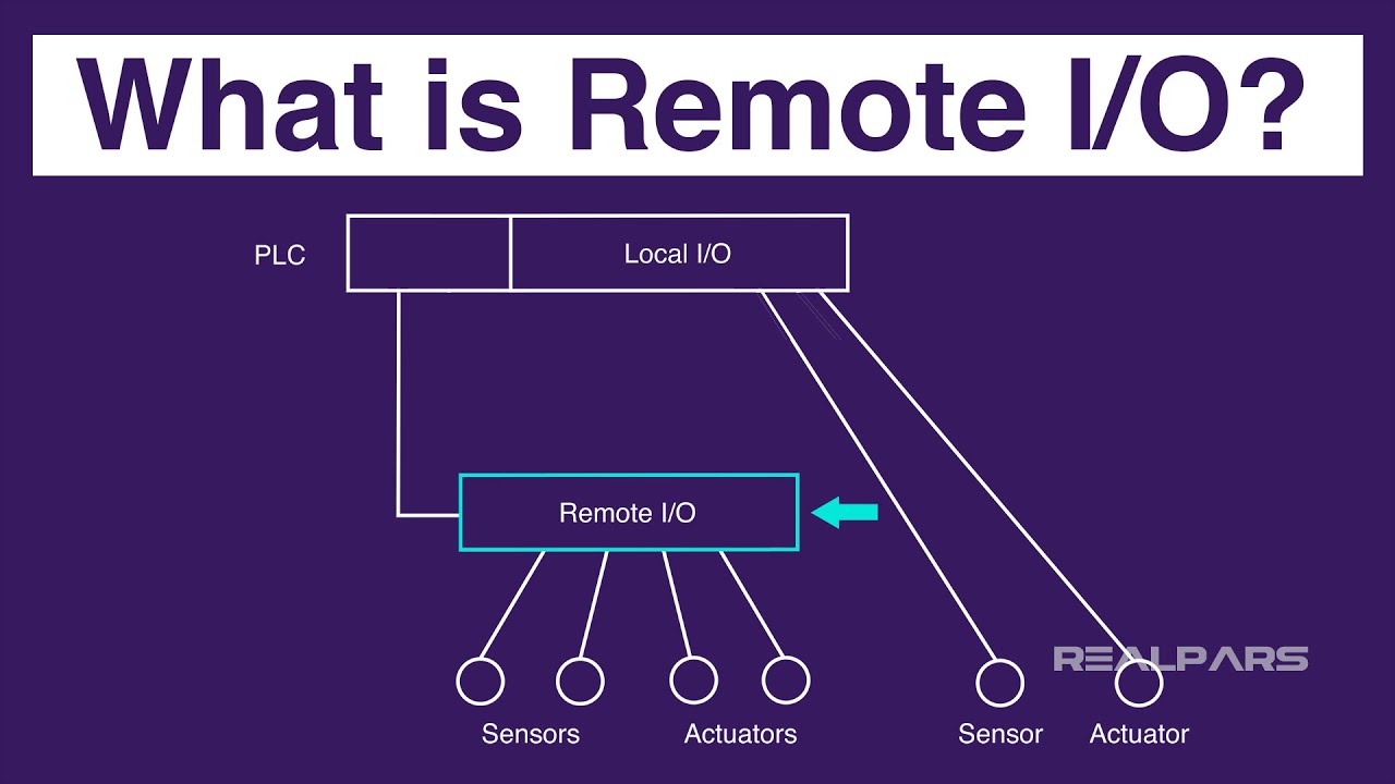
Image disclaimer: For identification and illustration only. It may show a product by another manufacturer and may not depict the exact item described; it is not a statement of any product’s quality, approval or performance. Third-party image and trademark rights belong to their owners. See full notice.
What Is It?
A Remote I/O (Remote Input/Output) unit is a distributed industrial control module that interfaces field devices with a central PLC or ALCMS over a communication network. Unlike the main PLC chassis which is typically located in a central equipment room, Remote I/O units are installed closer to the field equipment—such as CCR substations, runway edge cabinets, or junction boxes—to reduce the amount of long, costly cabling required for each sensor and actuator. A Remote I/O unit typically includes a mix of digital inputs (for switch states, alarm contacts), digital outputs (for relay drives, indicator lamps), analog inputs (for current, voltage, temperature sensors), and analog outputs (for setpoint control). The unit communicates with the host controller using industrial protocols such as Modbus, Profibus, Ethernet/IP, or Profinet, and receives its power from the same network cable (Power over Ethernet) or a separate 24 VDC supply. Remote I/O is the cornerstone of modern, scalable AGL control architecture.
Purpose & Function
Remote I/O exists to solve a basic economic and reliability problem with wiring every sensor and actuator on the airfield directly back to a central PLC: the cable runs would be enormous, expensive, and each one a potential point of signal degradation or damage over long distances. By placing an I/O module close to the field equipment it serves and communicating back to the central controller over a single network link, the architecture dramatically reduces cabling while keeping the connection between sensor and controller short and robust.
This distributed approach also directly supports system scalability and resilience: adding a new runway section or expanding a circuit doesn't require running new cable the full distance back to a central equipment room, and a fault isolated to one Remote I/O node is easier to diagnose and doesn't necessarily compromise the wiring or performance of I/O elsewhere on the network.
Where Is It Used?
Remote I/O units are deployed across the airfield wherever field devices need to be monitored or controlled. Key applications include:
- CCR Substations: Monitoring CCR status, current feedback, alarm contacts, and controlling brightness step switching via digital/analog outputs.
- Runway & Taxiway Lighting Cabinets: Controlling contactors for circuit switching and monitoring lamp failure detection circuits.
- Approach Lighting Systems: Controlling individual barrette circuits, monitoring lamp status, and managing sequenced flashing light timing.
- PAPI & Visual Aids: Monitoring lamp failure and controlling power to individual PAPI units.
- RWSL (Runway Status Light) Systems: Interfacing with stop bar sensors, runway guard light controllers, and take‑off hold light drivers.
- Obstruction Lighting: Monitoring beacon status and controlling flash patterns.
- Airfield Sensors: Reading wind speed/direction, visibility, and temperature sensors via analog inputs.
- Junction Boxes & Field Enclosures: Providing a local I/O point for a cluster of lights or sensors within a specific zone.
Installation & Location
Remote I/O racks mount on a DIN rail inside the substation, runway edge cabinet, or approach lighting shelter closest to the field devices they monitor and control, keeping the field wiring runs (CCR feedback, contactor control, lamp-failure detection) as short as possible rather than home-running every device back to a central PLC. Power is fed from the local cabinet's DC supply, and the unit's uplink to the main PLC or ALCMS network runs on fieldbus or Ethernet, typically via a fiber converter where the distance back to the control room is significant; field-side terminal wiring is kept on its own terminal blocks separate from the network-side cabling.
How Does It Work?
The Remote I/O unit operates as a slave device on an industrial network, receiving commands from and sending data to the host controller (PLC or ALCMS server). Key functional aspects include:
- I/O Mapping: Each input and output channel is assigned a unique address in the host controller's memory map, allowing the control program to read sensor states and write actuator commands transparently, as if the I/O were local.
- Communication Protocol: The unit uses a fieldbus or industrial Ethernet protocol (e.g., Modbus TCP, Profinet, Ethernet/IP) to exchange data cyclically with the host controller, typically at update rates of 10‑100 ms.
- Local Processing: Some advanced Remote I/O units support local logic execution (e.g., simple interlocking, alarm filtering), reducing the communication load on the host controller and enabling faster response times for critical signals.
- Diagnostics & Status: The unit reports its own health status (power supply, communication, module temperature) back to the host, enabling predictive maintenance and rapid fault isolation.
- Hot‑Swap Capability: Many Remote I/O modules are designed for hot‑swap replacement, allowing faulty modules to be replaced without powering down the entire system—critical for 24/7 airfield operations.
- Redundancy: Critical AGL systems often deploy Remote I/O units in redundant configurations (dual‑channel or ring topology) to ensure no single point of failure.
Remote I/O units are typically powered by 24 VDC from a local power supply, and their communication and power cabling is routed through separate conduits to ensure reliability and interference immunity.
System Architecture & Control Logic
The Remote I/O unit sits at the far end of the control chain, physically close to the sensors and actuators it serves and connected back to its host PLC or the ALCMS server over a fieldbus or Ethernet link rather than by running each individual signal wire all the way back to the control room. It behaves as a slave device: it does not make control decisions on its own, but continuously scans its local inputs (sensor states, contact closures, analog readings) and drives its local outputs (relays, contactors) strictly as instructed by the host. This is what lets a single PLC economically manage field devices scattered across an airfield — instead of long, individually wired runs for every sensor and actuator, only the fieldbus/Ethernet link and local power need to reach the remote location, with the Remote I/O unit doing the last-mile wiring to the equipment itself.
Host PLC / ALCMS Server
Issues read/write commands over fieldbus or Ethernet
Remote I/O Unit
Slave device — no local decision-making, executes host instructions
Local Field Wiring
Sensors, contacts & actuators at the remote location
How Data Moves Through the Remote I/O Unit
Field Devices
Sensors, contactors, lamp-failure contacts, CCR feedback
Local I/O Channels
Digital/analog inputs & outputs mapped to a unique address
Remote I/O Unit
I/O mapping, local logic & diagnostics processed on-module
Fieldbus / Industrial Ethernet
Modbus TCP, Profinet, Ethernet/IP — cyclic exchange every 10–100 ms
Host Controller
PLC / ALCMS reads inputs & writes commands as if I/O were local
Diagnostic Flagged
Health status (power, comms, temperature) reported to host
Redundant Path Takes Over
Dual-channel / ring topology preserves control
Physical Construction
The unit is built as a DIN-rail-mounted module or modular rack, with a base communication module handling network protocol translation and expansion I/O modules clipped alongside it through a backplane bus connector, allowing channel counts to be scaled without replacing the base unit. The housing is an extruded-aluminium or high-impact plastic shell with a conformally coated internal board to resist dust, humidity, and vibration in an unconditioned equipment room or field cabinet. Removable, colour-coded terminal blocks on each module allow field wiring to be disconnected without removing the module itself, and where PoE is used for power, the same Ethernet cable delivers both data and power through a single sealed connector, reducing the cable count into the enclosure. Where a field-mount rating is required rather than a panel-mount cabinet installation, the assembly is enclosed in a sealed IP65/IP67 housing with cable glands for each conductor entry.
Technical Parameters
| Parameter | Typical Value |
|---|---|
| Digital Inputs | 8, 16, or 32 channels (24 VDC, dry contact or PNP/NPN) |
| Digital Outputs | 8, 16, or 32 channels (relay or solid‑state, 24 VDC / 120 VAC) |
| Analog Inputs | 4, 8, or 16 channels (0‑10 V, 4‑20 mA, RTD, thermocouple) |
| Analog Outputs | 2, 4, or 8 channels (0‑10 V, 4‑20 mA) |
| Communication Protocols | Modbus TCP/RTU, Profibus DP, Profinet, Ethernet/IP, DeviceNet, CANopen |
| Communication Speed | 10/100 Mbps (Ethernet), 1.5 Mbps – 12 Mbps (fieldbus) |
| Scan/Update Rate | Typically 10 – 100 ms (configurable) |
| Power Supply | 24 VDC (nominal, 18‑32 VDC range), or PoE (Power over Ethernet) |
| Power Consumption | 2 – 15 W (depending on I/O count and type) |
| Operating Temperature | -25°C to +60°C (industrial grade) |
| Storage Temperature | -40°C to +85°C |
| Protection Class | IP20 (panel‑mount), IP65/IP67 (field‑mount with enclosure) |
| Mounting | DIN rail (standard) or panel mount |
| Diagnostics | Status LEDs, web server (optional), SNMP, or diagnostic registers |
| Certifications | UL, CE, IEC 61131‑2, EN 61000‑6‑2 (EMC immunity) |
Electrical Requirements
| Requirement | Typical Value |
|---|---|
| Circuit Position | Field-mounted or cabinet-mounted standalone powered I/O module |
| Power Supply | 24 VDC (nominal, 18‑32 VDC range), or PoE (Power over Ethernet) |
| Power Consumption | 2 – 15 W (depending on I/O count and type) |
| Isolation | I/O channels typically opto-isolated from field devices |
| Earthing | Enclosure bonded to local earth |
| Fault Protection | Internal overcurrent protection per channel |
Applicable Standards
IEC 61131‑2
Programmable controllers — equipment requirements and tests
IEC 61784‑1
Industrial communication networks — Fieldbus profiles
IEC 61822
Performance requirements for the Constant Current Regulators (CCRs) this Remote I/O unit monitors and controls
FAA AC 150/5345‑56
Specification for L-890 Airport Lighting Control and Monitoring System (ALCMS) — the host system Remote I/O extends field control and monitoring for
Installation Requirements
DIN-Rail Mounting
MechanicalMount the Remote I/O rack inside the substation, runway edge cabinet, or approach lighting shelter closest to the field devices it monitors and controls, keeping field wiring runs short.
Field Wiring Termination
ElectricalTerminate CCR feedback, contactor control, and lamp-failure detection wiring on its own terminal blocks, kept separate from the network-side cabling.
Local DC Power Feed
ElectricalFeed power from the local cabinet's DC supply, confirming voltage and loading before field wiring is energised.
Uplink Connection
ElectricalConnect the unit's uplink to the main PLC or ALCMS network on fieldbus or Ethernet, routing via a fiber converter where the distance back to the control room is significant.
I/O Mapping Verification
DocumentationVerify the I/O point mapping against the design before the rack is brought into service, confirming each field device maps to the correct point.
Pre-Commissioning Sign-off
DocumentationRecord rack position, field wiring terminations, and uplink route as-built before commissioning testing begins.
Testing & Commissioning
Power & Backplane Check
Pre-EnergisationConfirm 24 VDC or PoE supply reaches the base module and every expansion module registers correctly across the backplane bus.
Address Configuration Test
EnergisationVerify each module's network or fieldbus address is set correctly and free of conflicts before joining the live network.
Point-to-Point I/O Verification
Final AcceptanceForce each digital/analog input and output individually and confirm it maps correctly to the intended field device or controller tag.
Communication Protocol Test
Final AcceptanceConfirm the unit exchanges data correctly with the PLC/ALCMS over the configured protocol (Modbus, Profinet, Ethernet/IP, etc.).
Scan Rate / Latency Test
Final AcceptanceMeasure I/O update latency under load to confirm it meets the response time the connected circuit or sensor requires.
Fault / Diagnostic Signal Test
Final AcceptanceSimulate a module or communication fault and confirm the status LED and diagnostic register correctly report it upstream.
Documentation & As-Built Sign-off
Final AcceptanceRecord module addressing, I/O point mapping, and communication test results in the commissioning dossier for handover.
Inspection & Maintenance
Communication Link Test
Semi-annualTest the communication link to the controlling system to catch intermittent dropouts before they escalate.
Power Supply Check
AnnualVerify power input stability and inspect the supply for signs of stress or ageing.
Address Configuration Verification
AnnualConfirm module addressing remains correctly set and free of conflicts after any system changes.
EMI / Shielding Inspection
AnnualCheck shielding and grounding integrity, particularly near high-power cabling that can induce interference.
Enclosure Thermal Check
Semi-annualConfirm the outdoor enclosure is managing temperature extremes within the unit's rated range.
Common Field Issues
Communication Dropout
Remote I/O units rely on network communication; any interruption (cable damage, connector corrosion, switch failure) can cause loss of control. Use of redundant cabling, ring topology, and regular network cable inspection is essential.
Power Supply Failure
If the local 24 VDC power supply fails, the Remote I/O unit loses all I/O capability. Critical systems should have dual redundant power supplies and UPS backup.
Address Conflicts
Multiple Remote I/O units on the same network must have unique addresses. Misconfiguration can cause data corruption or loss of communication. Proper network planning and documentation is mandatory.
Electromagnetic Interference (EMI)
Remote I/O units located near high‑current equipment (CCRs, transformers) can experience EMI that corrupts communication or input readings. Use shielded cables and proper grounding techniques.
Firmware/Software Incompatibility
Updating the host PLC firmware without updating Remote I/O firmware can cause protocol mismatches. Always verify compatibility and use version‑controlled updates.
Temperature Extremes in Outdoor Enclosures
While rated for industrial temperatures, Remote I/O units in unventilated outdoor enclosures can overheat. Ensure enclosures are properly ventilated or cooled.
Troubleshooting Guide
Communication Dropout / Loss of I/O Control
Complete Loss of I/O Capability
Data Corruption or Intermittent Communication Faults
Erratic Input Readings or Comm Errors Near High-Current Equipment
Protocol Mismatch After a Host PLC Update
Failure Modes & Root Causes
I/O Module Power Supply Failure
Fieldbus / Industrial Ethernet Communication Failure
Address / Configuration Corruption
EMI-Induced Data Corruption
Enclosure Thermal Stress (Outdoor Cabinets)
Firmware Incompatibility After a Host Update
Safety & Operational Notes
Electrical Isolation Before Servicing
Electrical SafetyDe-energise and lock out the unit's power supply before working on its wiring or replacing modules, and verify zero energy before touching any terminal.
Configuration Backup Before Changes
OperationalBack up the unit's address and configuration settings before making changes, since a corrupted or mismatched configuration can silently drop the unit from the host network.
ESD Precautions When Handling Modules
MechanicalUse an anti-static wrist strap and follow ESD-safe handling procedures when removing or installing I/O modules, since static discharge can damage sensitive electronics.
EMI Source Awareness During Installation
OperationalRoute field wiring and position the unit away from high-current cabling, radar, or radio transmitters where practical, since electromagnetic interference is a known cause of data corruption on fieldbus and Ethernet links.
Enclosure Sealing After Servicing
OperationalConfirm gaskets and cable gland seals are correctly reinstated after servicing an outdoor cabinet, since moisture ingress is a leading cause of unexplained I/O faults in field-mounted units.
Engineering & Expert Notes
Network Segment Loading Affects Update Latency
NetworkAdding remote I/O nodes to an existing communication segment as the system grows is convenient, but each additional node slows the polling cycle for every other node sharing that segment. Check projected update latency against the number of nodes at design time rather than adding nodes until performance visibly degrades.
Match Power Source to Cable Run, Not Just Device Rating
ElectricalA Remote I/O unit rated for 24 VDC can still brown out intermittently if voltage drop over a long cable run from the supply isn't accounted for, especially once additional field devices are added to the same feed. Verify actual voltage at the unit under full load, not just at the source.
Isolate Analog Inputs From Switching Loads
Signal IntegrityAnalog current or voltage inputs monitoring CCR output or transformer condition are especially sensitive to electrical noise from nearby switching equipment; route analog signal cabling separately from power cabling and confirm shielding is grounded at one end only per the design.
Document I/O Mapping at Commissioning, Not After the Fact
DocumentationA Remote I/O unit's point mapping is easy to keep straight during commissioning and easy to lose track of after several rounds of field additions and reassignments; maintaining a living I/O schedule saves significant diagnostic time on any fault years later.
Route Redundant Communication Paths Independently
DesignRedundant network paths provide little real protection if both cables run through the same trench or duct bank, since a single excavation strike takes out both simultaneously. Verify physical route diversity for redundant links, not just logical redundancy in the network configuration.
Verify Firmware Compatibility Across Vendors' Remote I/O and Host PLC
IntegrationMixed-vendor installations can work correctly for years and then fail after a firmware update to one side changes protocol behaviour in a way the other side doesn't expect; test firmware updates on a bench setup that mirrors the field pairing before rolling them out live.
Frequently Asked Questions
Short answers about the remote i/o: what it is, how it works, specifications, standards, maintenance and common faults.
Q1What is a Remote I/O unit?
A Remote I/O (Remote Input/Output) unit is a distributed industrial control module that interfaces field devices with a central PLC or ALCMS over a communication network. It is installed close to the field equipment, such as CCR substations, runway edge cabinets or junction boxes, to reduce long, costly cabling for each sensor and actuator.
Q2What inputs and outputs does a Remote I/O unit provide?
A typical unit mixes digital inputs for switch states and alarm contacts, digital outputs for relay drives and indicator lamps, analog inputs for current, voltage and temperature sensors, and analog outputs for setpoint control. Typical counts are 8, 16 or 32 digital channels and 4, 8 or 16 analog inputs.
Q3Where is Remote I/O used in an AGL system?
At CCR substations to monitor status, current feedback and alarm contacts and to switch brightness steps, in runway and taxiway lighting cabinets to control contactors and monitor lamp failure detection circuits, and in approach lighting systems and other places where field devices need monitoring or control.
Q4How does a Remote I/O unit work?
It acts as a slave device on an industrial network. Each channel has a unique address in the host controller's memory map, so the control program reads inputs and writes outputs as if the I/O were local. Data is exchanged cyclically over a fieldbus or industrial Ethernet, typically at update rates of 10 ms to 100 ms.
Q5Which communication protocols does Remote I/O support?
Typical protocols are Modbus TCP and RTU, Profibus DP, Profinet, Ethernet/IP, DeviceNet and CANopen, at 10/100 Mbps Ethernet or 1.5 Mbps to 12 Mbps fieldbus speeds.
Q6How is a Remote I/O unit powered?
Typically by 24 V DC (18-32 V range) or PoE, drawing about 2 W to 15 W depending on I/O count and type. It is a standalone powered module, not part of the series lighting circuit, with I/O channels typically opto-isolated from field devices and per-channel overcurrent protection.
Q7What environmental ratings are typical?
Operating temperature is typically -25°C to +60°C (industrial grade) and storage -40°C to +85°C, with IP20 for panel-mount versions and higher ratings such as IP65 or IP67 for field-mounted versions.
Q8Which standards apply to Remote I/O?
The main references are IEC 61131-2 (programmable controllers), IEC 61784-1 (fieldbus profiles), IEC 61822 for the CCRs it monitors and controls, and FAA AC 150/5345-56 (L-890 ALCMS), the host system it extends. Always verify the current edition and your aerodrome's approved requirements.
Q9How often should Remote I/O be checked?
Typical intervals are semi-annual for communication link tests and enclosure thermal checks, and annual for power supply checks, address configuration verification and EMI and shielding inspection. Your airport's approved maintenance programme takes precedence.
Q10What are the common problems with Remote I/O?
Common problems are communication dropout, power supply failure, address conflicts, electromagnetic interference, firmware or software incompatibility and temperature extremes in outdoor enclosures. Erratic readings near high-current equipment often point to EMI, and a protocol mismatch can appear after a host PLC update.
Related Components
Go Beyond the Component. Understand the Complete AGL System.
You have explored the component. Now understand how it works within the complete Airfield Ground Lighting system.
Learn AGL from fundamentals to design, installation, testing, photometry, commissioning, maintenance and troubleshooting through structured technical training at Precision AGL Academy.
Build practical knowledge. Understand the circuit. Read the standards. Troubleshoot with confidence.
Your next step in AGL starts here.
Need expert guidance on Remote I/O selection, network architecture, or integration for your AGL system?
Precision AGL Academy provides advice on module selection, protocol choice, network redundancy, and field commissioning.
Follow the Academy
Important Notice, Disclaimer & Limitation of Liability
Please read before relying on any content on this page.
- Purpose and intended users. This page on Remote I/O is an independent educational and informational reference for competent, suitably trained and authorised airfield ground lighting (AGL) and aerodrome electrical personnel. It is not professional engineering, legal or regulatory advice, and using it does not create any professional or client relationship.
- Safety. Work on series circuits, constant current regulators (CCRs), isolating transformers, cables, connectors and lighting equipment can be fatal. Always apply the aerodrome’s permit-to-work and isolation/LOTO procedures, prove dead, use correctly rated instruments and PPE, and follow the manufacturer’s instructions. Nothing here authorises work on live equipment or the bypassing of any safety device or interlock.
- Aviation operations. Nothing here authorises installation, modification, energisation, adjustment, return to service, a change of operating category (CAT I/II/III), a NOTAM or any aerodrome certification or approval decision. These rest with the aerodrome operator, the air navigation service provider and the competent regulator.
- Specifications, ratings and typical values. Descriptions, parameters, ratings, dimensions, photometric values, wattages, service lives, maintenance tasks and intervals, failure modes, certifications (for example CE, FCC, UL or IEC marks) and part or type designations are general, typical and indicative. They may not match any particular product, make, model or version, and they are not a datasheet, design, specification, selection, sizing, procurement or acceptance criterion. The manufacturer’s current documents, the approved design and the project specification prevail.
- Standards and regulations. References to ICAO, FAA, IEC, IEEE, ISO, BIS, DGCA and other standards are paraphrased summaries for orientation only. They may be incomplete or out of date, and standards are revised from time to time. Consult the current official editions. Following this content does not guarantee compliance with any law, standard or regulatory approval, and the regulator’s requirements always prevail.
- No warranty. Content is provided “as is” and “as available”, without warranty of any kind, express or implied, including accuracy, completeness, currency or fitness for a particular purpose. Real installations differ in design, equipment make and model, age and condition.
- Limitation of liability. To the fullest extent permitted by applicable law, Precision AGL Academy, Precision AGL Solutions and their owners, authors and contributors are not liable for any injury, death, loss, damage, downtime, penalty or regulatory consequence, whether direct or indirect, arising from the use of, reliance on, or inability to use this content. Nothing in this notice excludes or limits any liability that cannot lawfully be excluded or limited.
- Independence, brands and no endorsement. This is an independent publication. It is not affiliated with, sponsored by or endorsed by ICAO, the FAA, the IEC, DGCA, AAI, any airport, regulator, supplier or equipment manufacturer. Third-party names, product designations, standard designations and trademarks (including Megger®, Siemens, Eaton, Crouse-Hinds, ADB SAFEGATE, Fluke, ABB and Honeywell) belong to their respective owners and are used only for identification and description. Mention of a brand, product or supplier is not a recommendation, and we do not sell, supply or quote for any component described.
- Images and third-party content. Images and illustrations are shown to help identify the type of component. They may show products of various manufacturers, may not depict the exact item described, and are not a statement about any product’s quality, approval or performance. Copyright and trademarks in third-party images, logos and photographs belong to their respective owners and are not claimed as ours. If you are a rights holder and want an image removed, replaced or credited, email precisionaglsolutions@gmail.com with the page address and we will act promptly.
- Training and services. Mentions of training, courses, consultation, advice, selection, installation, calibration or other support, including the “Learn…Certify” pathway, describe learning stages and are not an offer, quotation, tender or promise of any result. Contacting us or our replying creates no engagement or duty of care; an engagement exists only under a written agreement. We are not a regulator or certification body, and completing any course or reading this content is not a certification, accreditation or authorisation to work on any aerodrome.
- Copyright, privacy and corrections. © 2026 Precision AGL Academy. All rights reserved. Text, structure, compilations and diagrams may be viewed for personal reference and internal training only; any other copying, republication or commercial use needs our written permission. If you email, telephone or message us, we use your details only to respond and handle your matter, in line with applicable Indian law including the Digital Personal Data Protection Act, 2023; please do not send confidential or security-sensitive information. To display this page your browser requests fonts, icons and images from third-party servers, which receive your IP address and browser details under their own policies. Content is reviewed periodically with no obligation to update. To report an error, safety concern or rights issue, write to precisionaglsolutions@gmail.com.