Stop Bar Control Module
An electronic control unit that manages the operation of stop bar lights, receiving commands from the ATC or ALCMS and switching the stop bar circuit on/off, often with intensity control and interlock features to ensure safe sequencing with other AGL systems. The module ensures that stop bars are correctly illuminated only when the runway is occupied, preventing runway incursions.
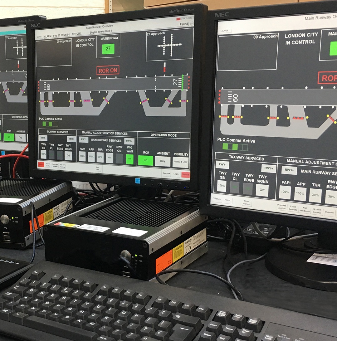
Image disclaimer: For identification and illustration only. It may show a product by another manufacturer and may not depict the exact item described; it is not a statement of any product’s quality, approval or performance. Third-party image and trademark rights belong to their owners. See full notice.
What Is It?
A Stop Bar Control Module is an electronic control unit that manages the operation of stop bar lights, receiving commands from the ATC or ALCMS and switching the stop bar circuit on/off, often with intensity control and interlock features to ensure safe sequencing with other AGL systems. The module ensures that stop bars are correctly illuminated only when the runway is occupied, preventing runway incursions. It typically interfaces with the constant current regulator (CCR), the ALCMS, and the stop bar monitoring unit to provide a complete stop bar control and supervision solution.
Purpose & Function
The stop bar control module exists to make sure a stop bar's on/off state is never left to chance or a fixture-level fault — it's the component that translates an actual ATC clearance decision into the physical illumination state of the barrier a pilot sees. Because a stop bar's entire safety function depends on it accurately reflecting whether the runway is actually clear, this module's interlocking logic is what prevents the bar from being switched off, and an aircraft cleared to cross, while a genuine conflict still exists.
Its coordination with other AGL systems is just as important as the switching itself: sequencing stop bar state correctly relative to runway lighting and other holding indicators is what stops mixed signals from ever reaching a pilot, which is exactly the kind of ambiguity that runway incursion defences are designed to eliminate entirely.
Where Is It Used?
Stop bar control modules are installed at runway holding positions on taxiways, particularly where precise control and sequencing are required. They are used on:
- Precision approach runways (CAT II and III) where stop bar control is critical
- Busy airports with high traffic volumes where automated control is beneficial
- Low visibility operations where reliable stop bar operation is essential
- Complex taxiway intersections with multiple stop bars requiring coordination
- Airports with ALCMS where remote and automated control is implemented
- Military airfields requiring robust and secure control systems
Installation & Location
The module is installed in an equipment shelter, CCR room, or dedicated control cabinet close to the stop bar circuit it serves, wired into the constant current regulator, the ALCMS, and the stop bar monitoring unit so switching commands, brightness settings, and status feedback can all pass through a single, centrally located point. Mounting is typically on an equipment rack or panel alongside related AGL control equipment, with clear labelling of the specific holding position or stop bar circuit each module serves, since a control room may house several modules covering different taxiway intersections. Control and monitoring cabling runs from the module out to the field circuit and to the stop bar monitoring unit over dedicated, clearly identified cable routes, kept separate from unrelated control circuits to avoid cross-connection errors during installation or later maintenance. Because the module's interlock logic is safety-critical, its wiring and configuration are verified against the site's specific stop bar sequencing requirements during commissioning, rather than installed to a generic default configuration.
How Does It Work?
Stop bar control modules operate as intelligent switching and control devices:
- Command Reception: The module receives on/off commands from the ATC via a control panel or from the ALCMS via digital communication (e.g., Modbus, Ethernet).
- Switching: It uses relays or solid-state switches to energize or de-energize the stop bar circuit, turning the lights on or off.
- Intensity Control: Some modules can adjust the intensity of the stop bar lights by controlling the CCR current step, matching the prevailing visibility conditions.
- Interlocks: The module may include interlock logic to prevent conflicting commands, such as ensuring that a stop bar is not turned on while a clearance bar is active, or that the stop bar is deactivated before the runway entrance light is turned on.
- Status Feedback: The module reports its status (on/off, intensity step, fault) to the ALCMS, providing real-time visibility for the controller.
System Architecture & Control Logic
The control module is the layer that turns a stop bar from a passive series-circuit fixture into an addressable safety device. Above it sits the ALCMS and, ultimately, the tower controller who issues the clearance decision; below it sits the CCR and the physical stop bar circuit. What makes the module's logic safety-critical rather than a simple relay is the interlocking it enforces between adjacent controlled elements: a stop bar cannot typically be switched off while the corresponding runway entrance lights or a downstream clearance bar are commanded on, and at CAT II/III-protected intersections the module may additionally require confirmation that the associated taxiway centreline lead-on lights are correctly sequenced before releasing the stop bar. At larger or more complex airports, the module is one node in a wider Advanced Surface Movement Guidance and Control System (A-SMGCS), where "follow-the-greens" routing software commands stop bars in and out of service automatically as part of a planned taxi route rather than through a single ATC button press — the module still performs the same switching and interlock function, just on commands originating from route logic instead of a human operator.
Command & Switching Sequence
Physical Construction
The module is built as an electronic control unit rather than an electromechanical one: a DIN-rail or panel-mounted PCB assembly carries the relay contacts or solid-state switches (rated up to 10A) that actually break and make the stop bar circuit, alongside the logic that interprets ALCMS commands and interlock inputs. Housing ranges from a simple IP20 enclosure for equipment-room installation up to an IP66 weatherproof housing where the module sits closer to the field, and status LEDs on the front panel — power, circuit status, communication, fault — give a technician an at-a-glance read without opening a cover or connecting test equipment. Terminal blocks bring in supply power (120/230V AC or 24V DC), interlock inputs from adjacent systems such as the clearance bar or runway entrance, and the communication bus (Modbus RTU or Ethernet) linking the module back to the ALCMS, keeping field wiring, logic, and switching contained in a single serviceable unit.
Technical Parameters
| Parameter | Typical Value |
|---|---|
| Supply Voltage | 120/230V AC or 24V DC |
| Control Outputs | Relay contacts (2x changeover) or solid-state switches (up to 10A) |
| Number of Controlled Circuits | 1 to 4 (depending on model) |
| Communication Interface | Modbus RTU (RS-485), Ethernet, or discrete I/O |
| Intensity Control | 5-step CCR interface (2.8A – 6.6A) |
| Interlock Inputs | Digital inputs for clearance bar, runway entrance, and other interlocks |
| Status Indicators | LEDs for power, circuit status, communication, and fault |
| Operating Temperature | -40°C to +70°C |
| Protection Class | IP20 (indoor) to IP66 (outdoor enclosure) |
| Mounting Type | DIN rail or panel mount |
| Power Consumption | < 10W |
| Compliance | CE, FCC, ICAO Annex 14 (for control and interlocking) |
Electrical Requirements
| Requirement | Typical Value |
|---|---|
| Supply Voltage | 120/230V AC or 24V DC, per installed variant |
| Power Consumption | < 10W |
| Control Wiring | Relay contacts (2x changeover) or solid-state switch outputs (up to 10A) to the stop bar CCR/circuit |
| CCR Interface | 5-step intensity command interface (2.8A–6.6A) to the associated constant current regulator |
| Interlock Wiring | Digital inputs wired from clearance bar, runway entrance, and other interlock sources |
| Communication Cabling | Modbus RTU (RS-485), Ethernet, or discrete I/O cabling to the ALCMS |
| Surge/Transient Protection | Input surge protection at the supply and interlock terminals |
| Earthing/Grounding | Enclosure and DIN rail/panel bonded to the local earth bus |
| Enclosure Rating | IP20 (indoor panel) to IP66 (outdoor enclosure), per installation |
Applicable Standards
ICAO Annex 14
Stop bar lighting and runway holding position requirements
FAA AC 150/5345‑56
Specification for L‑890 Airport Lighting Control and Monitoring System (ALCMS)
IEC 61508
Functional safety of electrical/electronic/programmable electronic safety-related systems — applicable to the interlock logic
ICAO Doc 9830
A‑SMGCS Manual — covers automated stop bar control as part of route/"follow‑the‑greens" logic
Installation Requirements
Shelter or Cabinet Mounting
CivilInstall the module in an equipment shelter, CCR room, or dedicated control cabinet close to the stop bar circuit it serves, mounted on an equipment rack or panel alongside related AGL control equipment.
Circuit Labelling
DocumentationClearly label the specific holding position or stop bar circuit each module serves, since a control room may house several modules covering different taxiway intersections.
Dedicated Cable Routing
ElectricalRun control and monitoring cabling from the module to the field circuit and to the stop bar monitoring unit over dedicated, clearly identified routes, kept separate from unrelated control circuits.
ALCMS & CCR Wiring
ElectricalWire the module into the constant current regulator, the ALCMS, and the stop bar monitoring unit so switching commands, brightness settings, and status feedback pass through the single control point.
Interlock Logic Verification
MechanicalVerify the module's wiring and configuration against the site's specific stop bar sequencing requirements, since the interlock logic is safety-critical and cannot be installed to a generic default.
Cross-Connection Check
ElectricalTrace and confirm each cable run against its labelled circuit before energisation, ruling out cross-connection with an unrelated control circuit.
Commissioning Sequence Test
DocumentationRun the module through its full switching sequence against the site-specific requirements during commissioning, rather than relying on factory defaults.
Pre-Energisation Sign-off
DocumentationRecord module position, circuit labelling, and cable routing as-built before the installation is closed out.
Testing & Commissioning
Control Wiring & Interlock Check
Pre-EnergisationVerify control wiring and interlocks between the module, the ATC/ALCMS command source, and the stop bar circuit before energisation.
Command & Switching Verification
EnergisationIssue on/off commands from ATC/ALCMS and confirm the module switches the stop bar circuit correctly and promptly each time.
Intensity Control Check
EnergisationWhere intensity control is provided, cycle through each setting and confirm the stop bar circuit responds at the correct level.
Interlock Sequencing Test
EnergisationConfirm the module correctly interlocks stop bar operation with adjacent taxiway/runway lighting, preventing conflicting states (e.g. stop bar off while runway occupied).
Fail-Safe Behaviour Test
Final AcceptanceRemove control or communication signal to the module and confirm the stop bar defaults to its safe (illuminated/closed) state rather than an undefined condition.
Response Time Measurement
Final AcceptanceMeasure the time from ATC/ALCMS command to stop bar state change, confirming it meets the response time required for runway incursion protection.
Documentation & As-Built Sign-off
Final AcceptanceRecord command-response, interlock, and fail-safe test results in the commissioning dossier for handover.
Inspection & Maintenance
Relay Contact Inspection
Semi-annualCheck relay contacts for pitting, arcing, or wear from repeated switching cycles, and replace relay modules on schedule to avoid intermittent circuit failures.
Interlock Logic Verification
AnnualTest every interlock input and safety condition against the commissioned logic to confirm the stop bar cannot be de-energized under an unsafe state.
Communication Link Test
Semi-annualVerify Modbus RTU or Ethernet link integrity, signal quality, and error-free command/status exchange with the ALCMS.
Terminal & Connector Tightness Check
AnnualRe-torque DIN-rail terminal and connector screws to spec, since loose terminations are a common source of nuisance faults and voltage drop.
Enclosure & Seal Inspection
AnnualInspect outdoor enclosure gaskets, glands, and vents for degradation to confirm the rated IP66 protection is still intact.
Firmware & Configuration Review
AnnualConfirm firmware is at the latest validated revision and that stored interlock and intensity-control parameters still match the commissioned configuration.
Supply Voltage Check
Semi-annualMeasure incoming 120/230V AC or 24V DC supply to confirm it stays within tolerance, since out-of-range supply can cause erratic switching or resets.
Status Indicator Function Test
QuarterlyConfirm power, circuit-status, communication, and fault LEDs respond correctly during a simulated fault to ensure field technicians can trust the indication.
Common Field Issues
Relay Contact Wear
Electromechanical relays used for switching can wear out over time, especially with frequent switching cycles. Regular inspection and replacement of relay modules is recommended to ensure reliable operation.
Communication Intermittency
Noise or poor connections on communication lines can cause intermittent loss of control or status feedback. Proper shielding, termination, and grounding are essential for reliable communication.
Interlock Logic Misconfiguration
Incorrect interlock settings can lead to unsafe conditions, such as allowing a stop bar to be deactivated while an aircraft is on the runway. Thorough testing and validation of interlock logic is critical during commissioning.
Troubleshooting Guide
Stop Bar Fails to Switch or Responds Sluggishly
Intermittent Loss of Control or Status Feedback
Unsafe Condition Identified During Interlock Testing
Failure Modes & Root Causes
Interlock Logic Fault Allowing the Bar to Switch Off Prematurely
Loss of Sequencing Coordination With Runway Lighting or Other Holding Indicators
Communication Fault Between Module and ALCMS
Firmware / Configuration Fault Producing an Incorrect State Output
Power Supply Failure to the Module
Safety & Operational Notes
Electrical Isolation Before Servicing
Electrical SafetyDe-energise the module's 120/230V AC or 24V DC supply, and separately the stop bar circuit it switches, before opening the housing or working on wiring; verify zero energy at both, since the module sits between two independent supplies.
Safety-Critical Interlock — Coordinate Before Isolating
OperationalThe module's interlock logic prevents a stop bar from being incorrectly switched off while a runway is occupied; taking it out of service removes that protection, so coordinate with ATC and raise a NOTAM before isolation, and confirm an interim procedure is in place for the affected stop bar.
Physical Lockout Over Software Disable
Electrical SafetyWhere the module is ALCMS-networked, use a physical lockout on the stop bar circuit during hands-on work rather than relying on a software-disabled or local-only mode, which a remote command could still override.
Insulation Test Before Re-Energisation
Electrical SafetyMegger test the stop bar circuit before restoring power after any cable, connector, or relay work, since a residual fault can produce a false or stuck state at re-energisation.
Airside Work Coordination
OperationalAny work affecting stop bar operation requires ATC/airside coordination and a NOTAM for the affected holding position, with personnel and vehicles kept clear per the aerodrome's safety management procedures.
Verify Interlock Sequencing Before Closing Out
ComplianceConfirm the module correctly sequences with the CCR, ALCMS, and stop bar monitoring unit — including fail-safe behaviour on a fault — before returning it to unattended operation; do not rely on a single successful on/off cycle as proof the interlock logic is sound.
Engineering & Expert Notes
Interlock Logic Is the Feature, Not a Formality
ComplianceNever bypass or defeat the module's interlock logic to force a stop bar on or off faster — the interlocking between stop bars, clearance bars, and entrance lights exists specifically to prevent the conflicting-light-state scenarios that cause incursions.
Confirm Which Layer Issued the Command Before Troubleshooting
TroubleshootingAt an A-SMGCS-equipped airport, a stop bar command may originate from follow-the-greens routing logic rather than a direct ATC button press. Confirm the command source before assuming a “stuck” stop bar is a hardware fault rather than a routing-software issue upstream.
Status Feedback Confirms Commanded State, Not Actual Illumination
TroubleshootingThe control module reports what it commanded, not necessarily what happened at the fixture. Cross-check against the separate monitoring unit's feedback before concluding a stop bar is working correctly.
Physical Lockout, Not a Panel Disable, for Any Hands-On Work
Electrical SafetyA software or panel-level disable can be overridden by a subsequent command arriving mid-task. Physically lock out the circuit instead of relying on a soft disable while working on it.
Re-Verify Interlock Sequencing After Any Firmware Update
CommissioningA firmware or logic update to the control module should trigger a full re-verification of interlock sequencing with adjacent stop bars and entrance lights — not just a check that the module itself powers up correctly.
Confirm CAT II/III Sequencing Is Actually Configured, Not Just Available
ComplianceAt precision-approach-protected intersections, confirm the module's requirement for taxiway centreline lead-on sequencing is genuinely configured and tested — not merely present as a feature the module supports.
Related Components
Frequently Asked Questions
Short answers about stop bar control modules: switching, interlocks, ratings, standards and maintenance.
Q1What is a stop bar control module?
It is an electronic control unit that manages stop bar lights, receiving commands from ATC or the ALCMS and switching the stop bar circuit on or off. It often provides intensity control and interlock features, and typically interfaces with the CCR, the ALCMS and the stop bar monitoring unit.
Q2What is the purpose of the stop bar control module?
It translates an actual ATC clearance decision into the physical state of the stop bar a pilot sees. Its interlock logic prevents the bar from being switched off, and an aircraft cleared to cross, while a genuine conflict still exists, and it sequences stop bar state correctly with other lighting so pilots never receive mixed signals.
Q3How does a stop bar control module work?
It receives on/off commands from an ATC control panel or from the ALCMS over Modbus or Ethernet, switches the circuit using relays or solid-state switches, can adjust intensity through the CCR current step, applies interlock logic, and reports on/off state, intensity step and faults back to the ALCMS.
Q4What interlocks does it provide?
Interlock logic prevents conflicting commands, such as turning a stop bar on while a clearance bar is active, or ensuring the stop bar is deactivated before the runway entrance light is turned on. Digital inputs take signals from clearance bar, runway entrance and other interlock sources.
Q5Where are stop bar control modules used?
At runway holding positions on taxiways, particularly on precision approach runways (CAT II and III), busy airports, low visibility operations, complex intersections with several stop bars, ALCMS-controlled airports and military airfields.
Q6What are typical specifications?
Supply is 120/230 V AC or 24 V DC, consuming under 10 W. Outputs are relay contacts (2× changeover) or solid-state switches up to 10 A, controlling 1 to 4 circuits. Communication is Modbus RTU (RS-485), Ethernet or discrete I/O, with a 5-step CCR interface (2.8 A to 6.6 A). Protection ranges from IP20 to IP66.
Q7Where is the module installed?
In an equipment shelter, CCR room or dedicated control cabinet close to the stop bar circuit it serves, on DIN rail or panel mount. It is wired to the CCR, ALCMS and stop bar monitoring unit so switching commands, brightness settings and status feedback pass through one central point.
Q8Which standards apply to stop bar control modules?
The main references are ICAO Annex 14 (stop bar lighting and holding position requirements), FAA AC 150/5345-56 (L-890 ALCMS), IEC 61508 (functional safety, applicable to the interlock logic) and ICAO Doc 9830 (A-SMGCS Manual). Always verify the current edition.
Q9How often should a stop bar control module be tested?
Typical intervals are quarterly for status indicator tests, semi-annual for relay contact inspection, communication link tests and supply voltage checks, and annual for interlock logic verification, terminal tightness, enclosure seals and firmware and configuration review. Your airport's approved maintenance programme takes precedence.
Q10What are the common problems and safety precautions?
Common issues are relay contact wear, intermittent communication from noise or poor connections, and interlock logic misconfiguration that could allow a stop bar to be deactivated while an aircraft is on the runway. Coordinate with ATC and raise a NOTAM before isolating, use a physical lockout on the stop bar circuit rather than a software disable, and verify interlock sequencing before closing out.
Go Beyond the Component. Understand the Complete AGL System.
You have explored the component. Now understand how it works within the complete Airfield Ground Lighting system.
Learn AGL from fundamentals to design, installation, testing, photometry, commissioning, maintenance and troubleshooting through structured technical training at Precision AGL Academy.
Build practical knowledge. Understand the circuit. Read the standards. Troubleshoot with confidence.
Your next step in AGL starts here.
Need expert guidance on stop bar control module selection or integration?
Precision AGL Academy provides advice on control logic, interlock design, and field testing of stop bar control systems.
Follow the Academy
Important Notice, Disclaimer & Limitation of Liability
Please read before relying on any content on this page.
- Purpose and intended users. This page on Stop Bar Control Module is an independent educational and informational reference for competent, suitably trained and authorised airfield ground lighting (AGL) and aerodrome electrical personnel. It is not professional engineering, legal or regulatory advice, and using it does not create any professional or client relationship.
- Safety. Work on series circuits, constant current regulators (CCRs), isolating transformers, cables, connectors and lighting equipment can be fatal. Always apply the aerodrome’s permit-to-work and isolation/LOTO procedures, prove dead, use correctly rated instruments and PPE, and follow the manufacturer’s instructions. Nothing here authorises work on live equipment or the bypassing of any safety device or interlock.
- Aviation operations. Nothing here authorises installation, modification, energisation, adjustment, return to service, a change of operating category (CAT I/II/III), a NOTAM or any aerodrome certification or approval decision. These rest with the aerodrome operator, the air navigation service provider and the competent regulator.
- Specifications, ratings and typical values. Descriptions, parameters, ratings, dimensions, photometric values, wattages, service lives, maintenance tasks and intervals, failure modes, certifications (for example CE, FCC, UL or IEC marks) and part or type designations are general, typical and indicative. They may not match any particular product, make, model or version, and they are not a datasheet, design, specification, selection, sizing, procurement or acceptance criterion. The manufacturer’s current documents, the approved design and the project specification prevail.
- Standards and regulations. References to ICAO, FAA, IEC, IEEE, ISO, BIS, DGCA and other standards are paraphrased summaries for orientation only. They may be incomplete or out of date, and standards are revised from time to time. Consult the current official editions. Following this content does not guarantee compliance with any law, standard or regulatory approval, and the regulator’s requirements always prevail.
- No warranty. Content is provided “as is” and “as available”, without warranty of any kind, express or implied, including accuracy, completeness, currency or fitness for a particular purpose. Real installations differ in design, equipment make and model, age and condition.
- Limitation of liability. To the fullest extent permitted by applicable law, Precision AGL Academy, Precision AGL Solutions and their owners, authors and contributors are not liable for any injury, death, loss, damage, downtime, penalty or regulatory consequence, whether direct or indirect, arising from the use of, reliance on, or inability to use this content. Nothing in this notice excludes or limits any liability that cannot lawfully be excluded or limited.
- Independence, brands and no endorsement. This is an independent publication. It is not affiliated with, sponsored by or endorsed by ICAO, the FAA, the IEC, DGCA, AAI, any airport, regulator, supplier or equipment manufacturer. Third-party names, product designations, standard designations and trademarks (including Megger®, Siemens, Eaton, Crouse-Hinds, ADB SAFEGATE, Fluke, ABB and Honeywell) belong to their respective owners and are used only for identification and description. Mention of a brand, product or supplier is not a recommendation, and we do not sell, supply or quote for any component described.
- Images and third-party content. Images and illustrations are shown to help identify the type of component. They may show products of various manufacturers, may not depict the exact item described, and are not a statement about any product’s quality, approval or performance. Copyright and trademarks in third-party images, logos and photographs belong to their respective owners and are not claimed as ours. If you are a rights holder and want an image removed, replaced or credited, email precisionaglsolutions@gmail.com with the page address and we will act promptly.
- Training and services. Mentions of training, courses, consultation, advice, selection, installation, calibration or other support, including the “Learn…Certify” pathway, describe learning stages and are not an offer, quotation, tender or promise of any result. Contacting us or our replying creates no engagement or duty of care; an engagement exists only under a written agreement. We are not a regulator or certification body, and completing any course or reading this content is not a certification, accreditation or authorisation to work on any aerodrome.
- Copyright, privacy and corrections. © 2026 Precision AGL Academy. All rights reserved. Text, structure, compilations and diagrams may be viewed for personal reference and internal training only; any other copying, republication or commercial use needs our written permission. If you email, telephone or message us, we use your details only to respond and handle your matter, in line with applicable Indian law including the Digital Personal Data Protection Act, 2023; please do not send confidential or security-sensitive information. To display this page your browser requests fonts, icons and images from third-party servers, which receive your IP address and browser details under their own policies. Content is reviewed periodically with no obligation to update. To report an error, safety concern or rights issue, write to precisionaglsolutions@gmail.com.