Stopway
A designated paved area beyond the end of a runway, designed to provide additional stopping distance for aircraft that overrun the runway during a rejected take‑off or landing. Constructed to support the weight of an aircraft and provide the necessary friction and structural integrity to decelerate the aircraft safely, protecting both the aircraft and the surrounding terrain.
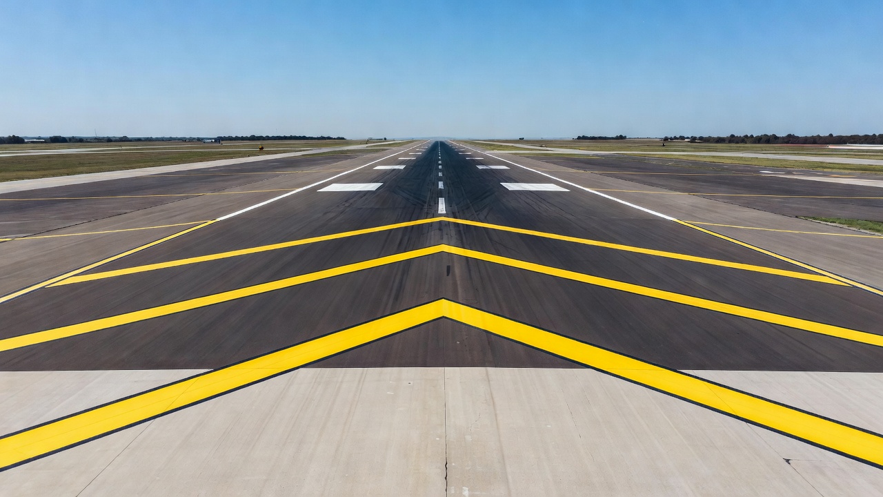
Image disclaimer: For identification and illustration only. It may show a product by another manufacturer and may not depict the exact item described; it is not a statement of any product’s quality, approval or performance. Third-party image and trademark rights belong to their owners. See full notice.
What Is It?
A Stopway (also known as an overrun area or emergency stopping area) is a prepared, paved surface located at the end of a runway, designed to provide a safe deceleration zone for aircraft that are unable to stop within the runway length. Unlike a blast pad, which is primarily designed to resist jet blast erosion, the stopway is structurally designed to support the full weight of an aircraft and provide adequate friction for braking and deceleration.
Key characteristics of a stopway include:
- Structural Strength: Designed to support the weight of the largest aircraft type expected to use the runway, using the ACN‑PCN (Aircraft Classification Number – Pavement Classification Number) system.
- Friction Characteristics: The surface is textured or grooved to provide adequate friction for braking, similar to or slightly less than the runway surface.
- Surface Type: Typically constructed of asphalt or concrete. Some overrun protection schemes add an Engineered Materials Arresting System (EMAS) — a bed of crushable material (e.g., cellular concrete or foamed glass) that decelerates an aircraft through deformation — but this is sited within the Runway End Safety Area beyond the stopway, not built into the stopway pavement itself.
- Markings: Yellow chevron markings (arrows pointing towards the runway) indicate that the area is not for normal take‑off or landing but is available for emergency overrun.
- Lighting: May have edge lighting — red, unidirectional lights facing the runway so only aircraft using the runway see them — to define the boundary, and sometimes obstruction lights to mark the end of the stopway.
- Length: Typically 60–300 m, sized to whatever accelerate‑stop distance the design aircraft's performance data calls for — not fixed by runway code or a standards‑mandated minimum.
Purpose & Function
The stopway's purpose is to extend the distance available for a rejected takeoff to come to a stop without extending the runway pavement itself, which matters because runway length drives declared distances used throughout normal operations while a stopway is credited only for accelerate-stop calculations. This distinction lets an airport certify higher takeoff weights for aircraft whose performance planning can use the additional stopping margin, without changing the runway's normal landing and takeoff distance figures or requiring the stopway to be built to the same unrestricted-use standard as the runway itself. Because it may only ever be used during a genuine emergency, its structural design is built specifically for a rare full-weight, high-speed deceleration event rather than for repeated routine traffic.
Where Is It Used?
Stopways are found at airports where the runway length is constrained by terrain, environmental factors, or cost, and where additional safety margins are required:
- Commercial Airports: At runways serving large passenger aircraft (e.g., Boeing 747, 777, Airbus A380), particularly where the available runway length is limited by site constraints.
- Military Airfields: At runways serving fighter and transport aircraft, where rapid take‑off and landing operations require additional safety margins.
- Remote and Island Airports: Where runway extension is physically impossible or prohibitively expensive, stopways provide a safety buffer.
- Airports with High Ambient Temperatures: Where aircraft performance is reduced due to high density altitude, requiring longer take‑off distances.
- Runways with High Traffic Volumes: Where the risk of overrun events is statistically higher, stopways provide an additional safety layer.
Stopways serve several critical functions:
- Runway End Safety: Providing a prepared surface that can safely accommodate an aircraft that overruns the runway, reducing the risk of damage and injury.
- Deceleration Support: The stopway's friction and structural strength allow the aircraft to decelerate using its brakes, reverse thrust, and aerodynamic drag.
- Aircraft Protection: Preventing the aircraft from entering rough terrain, ditches, or other hazards beyond the runway end.
- Compliance with International Standards: ICAO Annex 14 does not prescribe a fixed minimum or maximum stopway length; length is instead derived from the accelerate‑stop distance required for the critical aircraft, per the aeroplane's performance data. Many airports adopt a stopway specifically to satisfy that calculated distance without extending the runway pavement itself.
Installation & Location
The stopway is constructed in line with the runway, extending beyond the declared runway end at the same width as the runway pavement, and tied structurally into the runway end so an aircraft crossing onto it experiences no step, joint, or grade discontinuity during a rejected take-off. It's built to bear the weight of the aircraft type the runway serves, at least under the accelerate-stop loading condition, even though it isn't intended for routine take-off or landing use, and its surface friction characteristics are matched to the runway so braking performance doesn't change abruptly at the boundary. Because a stopway counts toward accelerate-stop distance calculations rather than take-off or landing distance, it's clearly delineated from the runway proper (through markings or lighting) so pilots and ATC are never in doubt about where the declared runway ends and the stopway begins.
How Does It Work?
The stopway functions through its design, materials, and integration with the runway system:
- Structural Design: The stopway is designed to support the dynamic loads of an aircraft that overruns the runway at speed. The pavement thickness and material are selected based on the design aircraft type, using the ACN‑PCN methodology. Typically, the stopway has a lower PCN than the runway but is still sufficient to support the aircraft.
- Friction Provision: The stopway surface is textured or grooved to provide a coefficient of friction of at least 0.4 (wet) to 0.6 (dry), allowing the aircraft to decelerate using its wheel brakes. Some stopways are designed with a "stopping" surface that provides higher friction than the runway itself.
- Engineered Materials (EMAS): Where fitted, an Engineered Materials Arresting System (EMAS) bed of crushable material (e.g., cellular concrete or foamed glass) is installed within the Runway End Safety Area, set back beyond the stopway. When an aircraft reaches the EMAS, the material crushes and absorbs the aircraft's kinetic energy, providing deceleration without relying on the aircraft's brakes.
- Drainage: The stopway is sloped to ensure rapid water runoff, preventing hydroplaning and maintaining friction in wet conditions.
- Markings and Lighting: Yellow chevron markings indicate the stopway boundary, and red unidirectional edge lighting (facing the runway) may be provided to help pilots identify the stopway at night. Where EMAS is used, it is typically marked with distinctive yellow or orange markings.
- Integration with Runway Lighting: The stopway lighting is typically interlocked with the runway lighting system to ensure that the stopway is illuminated when the runway is in use.
System Architecture & Control Logic
Stopway edge lighting shares the runway's series circuit, or a switched extension of it, rather than having a separate command point — the interlock means the stopway illuminates automatically whenever the runway circuit is energised, with no scenario in which the stopway is lit while the runway edge lights are not. EMAS installations, where present, carry no active electrical control at all; their "response" to an overrun is entirely passive and structural (crushable material absorbing kinetic energy), not instrumented or ALCMS-monitored.
Circuit & System Overview
The stopway itself is always a conventional high‑friction pavement that leaves deceleration to the aircraft's own brakes; where the overall overrun protection scheme also includes an EMAS bed within the Runway End Safety Area beyond it, that bed decelerates the aircraft through the physical crushing of its surface — useful where land is too short for a full-length RESA on its own.
Physical Construction
A stopway is built as a full structural pavement, engineered to a lower load-bearing standard than the runway proper but still capable of supporting the design aircraft's full weight during an overrun and providing adequate braking friction. Construction follows conventional flexible (asphalt) or rigid (concrete) pavement design: a compacted subgrade is overlaid with graded sub-base and base courses, topped with an asphalt wearing course or a reinforced concrete slab, with the total pavement thickness sized to the local soil strength and the aircraft loads the stopway must accommodate. The surface is grooved or tined during construction to maintain a wet-friction coefficient adequate for aircraft braking, and the pavement is graded with a longitudinal slope away from the runway and a transverse slope to shed surface water, tying into the airfield's broader drainage system. Where a site's overrun risk calls for it, an Engineered Material Arresting System (EMAS) bed — built from a crushable, energy-absorbing material and designed to decelerate an aircraft through controlled crushing rather than surface friction alone — may be installed within the Runway End Safety Area beyond the stopway; this is a specialised addition to the overall overrun protection scheme rather than a construction feature of the stopway pavement itself.
Technical Parameters
| Parameter | Typical Value |
|---|---|
| Length (from runway end) | Typically 60 m – 300 m (no fixed ICAO minimum/maximum — sized to the accelerate‑stop distance required for the design aircraft) |
| Width | Same as runway width, or wider |
| Pavement Type | Asphalt or Concrete (or EMAS for specialised applications) |
| Pavement Thickness | 200 mm – 400 mm (depending on soil conditions and aircraft loads) |
| Load Capacity (PCN) | Typically 50–80 (lower than runway but sufficient for the design aircraft) |
| Friction Coefficient (wet) | ≥ 0.4 (typical requirement) |
| Surface Texture | Grooved or tined for friction |
| Longitudinal Slope | Typically 1.0% – 1.5% (away from runway) |
| Transverse Slope | 1.5% – 2.0% (for drainage) |
| Markings | Yellow chevrons (arrows pointing towards runway) |
| Lighting | Red unidirectional edge lights (facing runway), obstruction lights at end |
| EMAS Bed (if provided) | Crushable material (cellular concrete/glass), length: 100–200 m — sited within the RESA beyond the stopway, at a setback that avoids jet‑blast damage |
Applicable Standards
ICAO Annex 14
Stopway dimensions, markings, and structural requirements
FAA AC 150/5300-13
Airport design standards for stopways and overrun areas
FAA AC 150/5320-6
Pavement design for airfields, including stopway construction
ICAO Doc 9157 (Aerodrome Design Manual)
Stopway design and EMAS implementation guidelines
FAA AC 150/5220-22
Engineered Materials Arresting Systems (EMAS) for aircraft overruns
Installation Requirements
Subgrade Preparation & Compaction
CivilCompact the subgrade and place graded sub-base and base courses sized to the local soil strength and the design aircraft loads before the wearing course is laid.
Grade Tie-in to Runway End
CivilTie the stopway pavement structurally into the runway end at matched width and grade so an aircraft crossing onto it experiences no step, joint, or grade discontinuity.
Drainage Slope Setting
CivilGrade the pavement with the design longitudinal slope away from the runway and transverse slope for drainage, tying into the airfield's broader drainage system.
Surface Grooving/Tining
CivilGroove or tine the finished surface during construction to achieve the wet-friction coefficient the design requires for aircraft braking.
Delineation Marking & Edge Lighting
ElectricalApply the yellow chevron markings and install edge/obstruction lighting so pilots and ATC are never in doubt where the declared runway ends and the stopway begins.
EMAS Bed Installation (Where Fitted)
CivilInstall the crushable, energy-absorbing EMAS bed at the far end to the specified length and material spec where the design calls for it.
Pre-Handover Sign-off
DocumentationRecord pavement thickness, grade tie-in, and delineation as-built before the stopway is accepted for service.
Testing & Commissioning
Subgrade & Structural Load Test
Pre-PavingTest subgrade compaction and bearing capacity against the design specification before paving, since the stopway must be structurally designed to support and decelerate an aircraft.
Pavement Bearing Capacity Verification
Construction AcceptanceVerify the completed pavement meets the bearing capacity required for the aircraft type the runway serves.
Runway Tie-In / Grade Continuity Check
Construction AcceptanceConfirm the stopway is tied structurally into the runway end with no step, joint, or grade discontinuity an aircraft would experience during a rejected take-off.
Chevron Marking Verification
Final AcceptanceConfirm chevron markings are complete, correctly positioned, and clearly distinguish the stopway from the runway proper.
Edge Light Circuit & Interlock Test
Final AcceptanceConfirm stopway edge lighting shares (or correctly extends) the runway's series circuit so it illuminates automatically whenever the runway circuit is energised, with no scenario where one is lit without the other.
EMAS Material Inspection
Final AcceptanceWhere an EMAS bed is installed, inspect material condition and confirm it meets the manufacturer's commissioning specification before the stopway is opened.
Friction Testing
Final AcceptanceMeasure surface friction with a calibrated friction tester against the design threshold before the stopway is accepted into service.
Documentation & As-Built Sign-off
Final AcceptanceRecord subgrade, bearing capacity, marking, and friction results alongside as-built dimensions in the commissioning dossier for handover.
Inspection & Maintenance
Friction Testing
AnnualTest surface friction with a calibrated friction tester and schedule grooving or micro-texturing if performance has dropped below the required level.
Chevron Marking Repaint
Every 1-2 yearsRepaint yellow chevron markings with high-visibility, reflective paint once fading from UV exposure and traffic reduces conspicuity.
EMAS Material Inspection
AnnualVisually inspect EMAS material for moisture ingress, freeze-thaw damage, and compaction, testing suspect sections and replacing compromised material.
Edge & Obstruction Light Test
MonthlyTest stopway edge and obstruction lights for lamp failure, cable damage, or power issues to keep the boundary clearly defined at night.
Pavement & Drainage Survey
AnnualSurvey for subgrade settlement, uneven surfaces, and drainage issues, repairing slopes to prevent water ponding and reduced friction.
Common Field Issues
Friction Degradation
Stopway surfaces can become polished or contaminated with rubber deposits from overrun events, reducing friction. Regular friction testing (using a friction tester) and periodic surface restoration (e.g., grooving, micro‑texturing) are essential to maintain the required stopping performance.
Faded Chevron Markings
The yellow chevron markings on stopways fade due to UV exposure and traffic. Faded markings can confuse pilots, leading to potential runway incursions. Regular repainting (every 1–2 years) with high‑visibility, reflective paint is necessary.
EMAS Material Degradation
EMAS materials (cellular concrete/glass) can degrade over time due to moisture ingress, freeze‑thaw cycles, and compaction from aircraft overruns. Regular visual inspections and material testing are required to ensure that the EMAS remains effective. Compromised sections may need replacement.
Lighting Failures
Stopway edge lights and obstruction lights can fail due to lamp burnout, cable damage, or power supply issues. Regular testing and prompt repair are necessary to ensure that the stopway boundary is clearly defined, especially at night and in low visibility.
Pavement Settlement and Drainage Issues
Subgrade settlement can cause uneven pavement surfaces and affect drainage, leading to water ponding and reduced friction. Regular surveys and repairs to restore proper slopes and drainage are essential.
Troubleshooting Guide
Reduced Friction / Aircraft Overrun Risk
Chevron Markings Not Legible from the Air
EMAS Bed Shows Compression, Cracking, or Rutting
Stopway Edge or Obstruction Light Outage
Water Ponding on the Stopway Surface
Failure Modes & Root Causes
Surface Friction Degradation
Chevron Marking Degradation
EMAS Bed Degradation
Lighting Circuit Failure
Drainage / Cross-Slope Failure
Safety & Operational Notes
Airside Work Coordination
OperationalAny work on or adjacent to the stopway requires ATC/airside coordination and a NOTAM where the surface, markings, or edge lighting will be affected, with vehicle and personnel movement kept clear of the runway strip per the aerodrome's safety management procedures.
Edge Lighting Circuit Isolation
Electrical SafetyWhere red stopway edge lights or obstruction lights are fitted, de-energise and lock out the associated CCR before working on fixtures, cabling, or transformers along the stopway boundary.
FOD Control on the Surface
OperationalKeep tools, fasteners, and repair materials accounted for at all times when working on the stopway pavement, and sweep the area clear before reopening it, since foreign object debris here is as hazardous as on the runway itself.
Vehicle Access & Marking
OperationalConfirm vehicle access routes onto the stopway are agreed with airside operations, and do not disturb or obscure the yellow chevron markings that indicate the area is not for normal take-off or landing.
Heavy Equipment & Pavement Work
Personnel SafetyFollow standard construction-site precautions for paving, grading, or crushable-material work, including plant exclusion zones, banksman use, and edge-of-pavement fall or drop-off hazards where the stopway meets surrounding terrain.
Surface Condition Awareness
OperationalInspect and report standing water, ice, or debris on the stopway promptly, since its friction and load-bearing performance during an overrun depends on the surface being maintained to the same standard as the runway.
Insulation Test Before Re-Energisation
Electrical SafetyAfter any lighting circuit work, megger test the affected loop before restoring power, since a residual fault at re-energisation can trip the CCR or damage healthy fixtures on the same circuit.
Restore to Compliant State
ComplianceDo not leave the stopway surface, markings, or lighting non-compliant after maintenance; verify condition and conformance before closing out the work and cancelling the associated NOTAM.
Engineering & Expert Notes
A Stopway's Structural Strength Requirement Is Often Underestimated
DesignBecause a stopway isn't used for routine takeoff or landing traffic, its pavement strength is sometimes designed to a lower standard than the runway; but it must still support the full weight of the design aircraft during a rejected takeoff, so ACN-PCN calculations should not be relaxed just because the surface sees infrequent loading.
Lighting on the Stopway Must Be Distinguishable From the Runway Edge
Visual AidsWhere edge or centreline lighting continues onto or adjacent to a stopway, pilots need an unambiguous visual cue that they've passed the actual runway end; verify that the lighting configuration and any colour transition at the runway-stopway boundary meets the applicable standard and isn't left to a generic continuation of runway lighting.
Friction Testing Shouldn't Be Skipped Because Traffic Is Light
MaintenanceA stopway sees far less routine wear than the runway proper, which can lead to friction testing being deprioritised in the maintenance schedule; but rubber deposit is not the concern here — weathering, contamination, and surface degradation still reduce braking friction over time and need the same periodic verification as the runway.
FOD Risk Is Easy to Overlook on an Area That "Isn't Really Used"
OperationalBecause a stopway doesn't see routine aircraft movements, it can be treated as lower priority for FOD inspection than the runway; but in the rare event it's used, it's used under exactly the conditions — a high-speed rejected takeoff — where debris does the most damage. Keep it on the same inspection cycle as the runway.
Drainage Design Deserves the Same Attention as the Runway's
DesignWater pooling on a stopway surface degrades braking friction in exactly the scenario the stopway exists for — an aircraft already struggling to stop within the runway length; cross-fall and drainage design should match runway-grade standards rather than being value-engineered down as a secondary surface.
Confirm Published Distances Reflect the Stopway, Not Just the Runway
ComplianceAny change to a stopway's length, strength, or surface condition can affect published Accelerate-Stop Distance Available (ASDA) figures; changes to the stopway need to be communicated for aeronautical information and declared distance recalculation, not just recorded as a pavement maintenance item.
Related Components
Frequently Asked Questions
Short answers about stopways: purpose, length, construction, lighting, standards and maintenance.
Q1What is a stopway?
A stopway, also called an overrun area or emergency stopping area, is a prepared paved surface beyond the end of a runway that gives an aircraft a safe deceleration zone during a rejected take-off. Unlike a blast pad, which mainly resists jet blast erosion, a stopway is designed to support the full weight of an aircraft and provide friction for braking.
Q2What is the purpose of a stopway?
It extends the distance available for a rejected take-off to come to a stop without lengthening the runway pavement. A stopway is credited only for accelerate-stop calculations, so it does not change the runway's normal declared landing and take-off distances, but it can let an airport certify higher take-off weights.
Q3How long is a stopway?
Typically 60 m to 300 m. ICAO Annex 14 does not prescribe a fixed minimum or maximum length; it is sized to the accelerate-stop distance required for the design aircraft, based on the aeroplane's performance data. It is normally built at the same width as the runway, or wider.
Q4What is a stopway built from, and how strong is it?
Typically asphalt or concrete, 200 mm to 400 mm thick depending on soil conditions and aircraft loads. Load capacity is typically PCN 50 to 80, lower than the runway but sufficient for the design aircraft under the ACN-PCN system. The surface is grooved or tined to give a wet friction coefficient of at least 0.4.
Q5How is a stopway marked and lit?
Yellow chevron markings with arrows pointing towards the runway show that the area is not for normal take-off or landing. It may have red unidirectional edge lights facing the runway, so only aircraft using the runway see them, and sometimes obstruction lights at the end of the stopway.
Q6Is a stopway the same as EMAS?
No. EMAS (Engineered Materials Arresting System) is a bed of crushable material such as cellular concrete or foamed glass that decelerates an aircraft through deformation. Where fitted, it is sited within the Runway End Safety Area beyond the stopway, not built into the stopway pavement. It is passive and has no electrical control.
Q7How is stopway lighting controlled?
Stopway edge lighting shares the runway's series circuit, or a switched extension of it, with no separate command point. It is interlocked so the stopway illuminates automatically whenever the runway circuit is energised.
Q8How does a stopway drain?
It is sloped for rapid runoff to prevent hydroplaning and keep friction in wet conditions, typically with a longitudinal slope of 1.0% to 1.5% away from the runway and a transverse slope of 1.5% to 2.0%.
Q9Which standards apply to stopways?
The main references are ICAO Annex 14, FAA AC 150/5300-13 (airport design), FAA AC 150/5320-6 (pavement design), ICAO Doc 9157 (Aerodrome Design Manual) and FAA AC 150/5220-22 for EMAS. Always verify the current edition and your aerodrome's approved requirements.
Q10How often should a stopway be inspected and maintained?
Typical intervals are monthly for edge and obstruction light tests, annual for friction testing, EMAS inspection and pavement and drainage surveys, and every one to two years for repainting chevron markings. Your airport's approved maintenance programme takes precedence.
Q11What are the common stopway problems?
The common issues are friction degradation from polishing or rubber deposits, faded chevron markings, EMAS degradation from moisture, freeze-thaw and compaction, edge or obstruction light failures, and subgrade settlement that causes ponding and reduced friction.
Go Beyond the Component. Understand the Complete AGL System.
You have explored the component. Now understand how it works within the complete Airfield Ground Lighting system.
Learn AGL from fundamentals to design, installation, testing, photometry, commissioning, maintenance and troubleshooting through structured technical training at Precision AGL Academy.
Build practical knowledge. Understand the circuit. Read the standards. Troubleshoot with confidence.
Your next step in AGL starts here.
Need expert guidance on stopway design, maintenance, or EMAS implementation?
Precision AGL Academy provides advice on stopway pavement design, friction management, EMAS systems, and compliance with ICAO/FAA standards.
Follow the Academy
Important Notice, Disclaimer & Limitation of Liability
Please read before relying on any content on this page.
- Purpose and intended users. This page on Stopway is an independent educational and informational reference for competent, suitably trained and authorised airfield ground lighting (AGL) and aerodrome electrical personnel. It is not professional engineering, legal or regulatory advice, and using it does not create any professional or client relationship.
- Safety. Work on series circuits, constant current regulators (CCRs), isolating transformers, cables, connectors and lighting equipment can be fatal. Always apply the aerodrome’s permit-to-work and isolation/LOTO procedures, prove dead, use correctly rated instruments and PPE, and follow the manufacturer’s instructions. Nothing here authorises work on live equipment or the bypassing of any safety device or interlock.
- Aviation operations. Nothing here authorises installation, modification, energisation, adjustment, return to service, a change of operating category (CAT I/II/III), a NOTAM or any aerodrome certification or approval decision. These rest with the aerodrome operator, the air navigation service provider and the competent regulator.
- Specifications, ratings and typical values. Descriptions, parameters, ratings, dimensions, photometric values, wattages, service lives, maintenance tasks and intervals, failure modes, certifications (for example CE, FCC, UL or IEC marks) and part or type designations are general, typical and indicative. They may not match any particular product, make, model or version, and they are not a datasheet, design, specification, selection, sizing, procurement or acceptance criterion. The manufacturer’s current documents, the approved design and the project specification prevail.
- Standards and regulations. References to ICAO, FAA, IEC, IEEE, ISO, BIS, DGCA and other standards are paraphrased summaries for orientation only. They may be incomplete or out of date, and standards are revised from time to time. Consult the current official editions. Following this content does not guarantee compliance with any law, standard or regulatory approval, and the regulator’s requirements always prevail.
- No warranty. Content is provided “as is” and “as available”, without warranty of any kind, express or implied, including accuracy, completeness, currency or fitness for a particular purpose. Real installations differ in design, equipment make and model, age and condition.
- Limitation of liability. To the fullest extent permitted by applicable law, Precision AGL Academy, Precision AGL Solutions and their owners, authors and contributors are not liable for any injury, death, loss, damage, downtime, penalty or regulatory consequence, whether direct or indirect, arising from the use of, reliance on, or inability to use this content. Nothing in this notice excludes or limits any liability that cannot lawfully be excluded or limited.
- Independence, brands and no endorsement. This is an independent publication. It is not affiliated with, sponsored by or endorsed by ICAO, the FAA, the IEC, DGCA, AAI, any airport, regulator, supplier or equipment manufacturer. Third-party names, product designations, standard designations and trademarks (including Megger®, Siemens, Eaton, Crouse-Hinds, ADB SAFEGATE, Fluke, ABB and Honeywell) belong to their respective owners and are used only for identification and description. Mention of a brand, product or supplier is not a recommendation, and we do not sell, supply or quote for any component described.
- Images and third-party content. Images and illustrations are shown to help identify the type of component. They may show products of various manufacturers, may not depict the exact item described, and are not a statement about any product’s quality, approval or performance. Copyright and trademarks in third-party images, logos and photographs belong to their respective owners and are not claimed as ours. If you are a rights holder and want an image removed, replaced or credited, email precisionaglsolutions@gmail.com with the page address and we will act promptly.
- Training and services. Mentions of training, courses, consultation, advice, selection, installation, calibration or other support, including the “Learn…Certify” pathway, describe learning stages and are not an offer, quotation, tender or promise of any result. Contacting us or our replying creates no engagement or duty of care; an engagement exists only under a written agreement. We are not a regulator or certification body, and completing any course or reading this content is not a certification, accreditation or authorisation to work on any aerodrome.
- Copyright, privacy and corrections. © 2026 Precision AGL Academy. All rights reserved. Text, structure, compilations and diagrams may be viewed for personal reference and internal training only; any other copying, republication or commercial use needs our written permission. If you email, telephone or message us, we use your details only to respond and handle your matter, in line with applicable Indian law including the Digital Personal Data Protection Act, 2023; please do not send confidential or security-sensitive information. To display this page your browser requests fonts, icons and images from third-party servers, which receive your IP address and browser details under their own policies. Content is reviewed periodically with no obligation to update. To report an error, safety concern or rights issue, write to precisionaglsolutions@gmail.com.