Visual Docking Guidance System
An advanced apron‑side system that provides pilots with real‑time visual guidance to safely park aircraft at the stand. Using laser, radar, or camera sensors, VDGS displays azimuth, lateral deviation, distance to stop, and stop position on a large display, enabling precise and efficient aircraft parking without ground marshaller assistance.
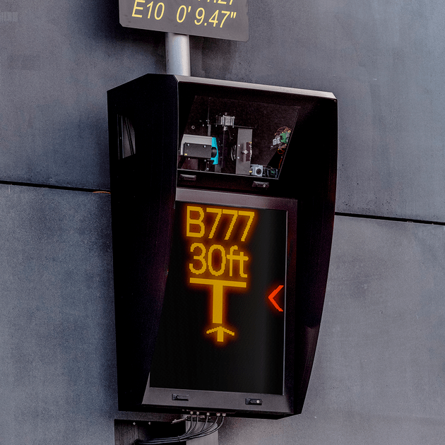
Image disclaimer: For identification and illustration only. It may show a product by another manufacturer and may not depict the exact item described; it is not a statement of any product’s quality, approval or performance. Third-party image and trademark rights belong to their owners. See full notice.
What Is It?
A Visual Docking Guidance System (VDGS) is an automated system installed at aircraft parking stands that provides pilots with clear, real‑time visual guidance to park the aircraft accurately and safely. The system typically consists of a sensor unit (laser, radar, or camera) mounted on the gate or a mast, and a large visual display (LED or LCD) placed in front of the aircraft, visible from the cockpit.
VDGS reduces reliance on ground marshallers, improves turnaround efficiency, and enhances safety by:
- Azimuth Guidance: Showing the aircraft's lateral position relative to the centreline.
- Distance to Stop: Displaying the remaining distance to the stopping point.
- Stop Indication: Providing a clear signal when the aircraft has reached the correct parking position.
- Type Selection: Allowing the system to be configured for different aircraft types, adjusting the stop position accordingly.
VDGS is a key component of modern airport apron management, supporting high‑traffic operations and reducing the risk of ground incidents.
Purpose & Function
VDGS exists to replace a marshaller's visual judgement, however experienced, with a precise, repeatable stopping reference that puts the aircraft exactly where the jet bridge, ground service equipment, and wingtip clearances on that stand were designed for. Because gate turnaround time and stand safety both depend on the aircraft stopping in the same position every time, the system's real value is in that consistency at high traffic volume, rather than only in replacing a person with a machine; a marshaller's accuracy can vary with fatigue, visibility, and workload, while the system's reference position does not. Configuring the display for the specific aircraft type ensures the stop point itself is also correct for that aircraft's dimensions, not just precisely repeatable.
Where Is It Used?
VDGS is deployed at airports worldwide, particularly at busy commercial hubs and passenger terminals:
- Passenger Boarding Gates: Installed at jetbridge positions to guide aircraft accurately to the bridge for efficient passenger boarding.
- Cargo Stands: Used to park freighter aircraft precisely for cargo handling operations.
- Remote Stands: At stands without jetbridges, VDGS assists in parking aircraft that will be serviced by stairs and ground equipment.
- Maintenance Hangars: Used to guide aircraft into hangars for maintenance.
- Military Airfields: For precise parking of military aircraft in confined spaces.
VDGS serves several operational functions:
- Precision Parking: Ensuring the aircraft stops within the designated stand markings, aligning with jetbridges, fuel hydrants, and ground power connections.
- Safety Enhancement: Reducing the risk of collisions with ground equipment, other aircraft, or terminal buildings.
- Operational Efficiency: Reducing parking time and minimising the need for ground marshaller intervention, especially in adverse weather.
- Data Collection: Providing operational data (parking time, type, deviations) for analysis and performance improvement.
Installation & Location
The sensor unit is mounted on the terminal building facade, a dedicated gate canopy, or a freestanding mast positioned on the stand centreline extended, at a height and setback calculated from the specific stand's parking geometry so its field of view covers the full approach path the aircraft nose will follow. The visual display is mounted below or alongside the sensor at a height and angle chosen so it remains clearly legible from the cockpit throughout the final approach to the stop point, with mounting hardware rated to hold the display rigid against wind loading given its size and elevated position. Both units are wired back to a processing cabinet, typically housed within the terminal building or an adjacent equipment room, over a protected cable run, with the system's parking geometry for each aircraft type configured against the specific stand's surveyed dimensions rather than a generic default. Where a stand serves multiple aircraft types, the sensor and display positions are set out to give adequate coverage and visibility across the full range of nose heights and cockpit positions the stand is designed to accommodate.
How Does It Work?
VDGS operates through an integrated system of sensors, processing units, and display technology:
- Sensor Technology: The system uses one of several sensor types to track the aircraft's position and orientation:
- Laser Scanners: Emit pulses of light to measure distance and angle to the aircraft nose, providing high‑accuracy position data.
- Radar Systems: Use microwave signals to detect the aircraft's position, effective in all weather conditions.
- Camera/Image Processing: Use high‑resolution cameras and computer vision algorithms to identify the aircraft type, position, and orientation.
- Magnetic Loop Sensors: Embedded in the pavement to detect the aircraft's nose gear position (older systems).
- Data Processing: The sensor data is processed by a dedicated computer that calculates the aircraft's position, heading, and distance to the target stop point. The system is pre‑programmed with the parking geometry for each aircraft type.
- Visual Display: The processed information is presented on a large, high‑brightness LED or LCD display placed in front of the aircraft (on the gate or a mast). The display shows:
- Azimuth Scale: Moving bars or arrows indicating left/right deviation from centreline.
- Distance Display: A numerical countdown of the remaining distance to the stop point (in metres or feet).
- Stop Signal: A prominent "STOP" message or a colour change (red to green) when the aircraft is correctly positioned.
- Aircraft Type: The selected aircraft type may be displayed to confirm correct configuration.
- Integration with Apron Systems: VDGS can be integrated with the apron management system, providing data to the ALCMS, and interfacing with jetbridge positioning and ground power systems.
System Architecture & Control Logic
VDGS is architecturally closer to a small, self-contained control system than most AGL components: a local processing unit continuously reads the position sensor (laser, radar, or camera), compares the aircraft's live position and closing speed against the stored parking geometry for the assigned aircraft type, and drives the display in real time — azimuth guidance, distance countdown, and the final stop signal are all outputs of this one control loop rather than independently switched indications. The system typically receives its aircraft-type and stand-assignment data from an external source — a gate management system or airport operational database (AODB) — over a network interface, so the docking sequence it runs is parameterised externally even though the moment-to-moment guidance loop is entirely local to the stand. Fault handling is also local-first: if the sensor loses track of the aircraft or its own self-check fails, the system defaults to a stop or blank display rather than continuing to guide from stale data, and that fault condition is what gets reported upstream to the airport's central monitoring system rather than any raw sensor data.
How VDGS Guides the Aircraft to a Precision Stop
Sensor Tracks Aircraft Nose
Laser scanner, radar, camera, or magnetic loop
Processor Calculates Position
Heading & distance to stop point, matched to pre‑programmed aircraft type geometry
Left / Right Deviation
Moving bars guide the pilot back to centreline
Remaining Distance
Numerical readout in metres or feet
Aircraft Reaches Stop Point
Display switches to STOP — colour changes red to green
Physical Construction
The display unit is a large-format, sunlight-readable LED or LCD panel housed in a weatherproof, UV-stabilised enclosure, mounted on a pole, wall bracket, or gantry positioned so it sits directly in the pilot's forward line of sight on final approach into the stand. Behind or beside the display, a separate sensor housing carries the laser scanner, radar, or camera module used to track the aircraft's position and closing speed, aimed down the stand centreline and weatherproofed to the same or a higher ingress-protection rating than the display itself. Both units are cabled back to a control cabinet housing the processing electronics, aircraft-type database, and communications interface (Ethernet, RS‑485, or wireless), typically sited at the base of the pole or in a nearby equipment room, with surge protection and an uninterruptible supply to keep the system available during stand operations. The mounting structure is engineered to withstand jet blast and wind loading while holding the display and sensor alignment stable to the tolerances needed for accurate stop-position guidance.
Technical Parameters
| Parameter | Typical Value |
|---|---|
| Sensor Technology | Laser scanner, Radar, Camera, or Magnetic Loop |
| Measurement Range (Distance) | 1 m – 100 m (depending on sensor) |
| Accuracy (Position) | ±0.1 m (laser), ±0.3 m (radar/camera) |
| Display Type | LED or LCD (high brightness, sunlight‑readable) |
| Display Size | Typically 1.5 m × 1.0 m (large format) |
| Viewing Angle | Wide angle for visibility from cockpit |
| Supported Aircraft Types | A320, B737, B777, A380, etc. (configurable) |
| Communication Protocol | Ethernet, RS‑485, or wireless |
| Power Supply | 230 V AC / 50 Hz (or 110 V / 60 Hz) |
| Operating Temperature | -20°C to +55°C |
| Protection Class | IP54 – IP67 (depending on location) |
| Mounting | Pole‑mounted, wall‑mounted, or gantry‑mounted |
Electrical Requirements
| Requirement | Typical Value |
|---|---|
| Circuit Position | Standalone mains-powered docking guidance system, independent of the series lighting circuit |
| Power Supply | 230 V AC / 50 Hz (or 110 V / 60 Hz) |
| Isolation | Electrically independent of the airfield series lighting circuit |
| Earthing | Structure/mast bonded to the earth grid |
| Fault Protection | Mains-side breaker/RCD protection; self-monitoring with fault reporting |
| Communication Isolation | Data interfaces (Ethernet, RS‑485, or wireless) electrically isolated from the power circuit |
Photometric Requirements
| Parameter | Typical Value |
|---|---|
| Display Luminance | High-brightness LED/LCD, sunlight-readable in direct sun without washout |
| Automatic Brightness Control | Ambient light sensor-driven dimming for day/twilight/night conditions to avoid glare after dark |
| Viewing Angle | Legible across the pilot's expected line-of-sight cone on final approach into the stand |
| Display Colour Coding | Red/green (and amber where fitted) status colours within recognisable aviation colour conventions |
| Character/Symbol Size | Sized to the display's rated reading distance for the stand's approach length |
| Laser Sensor Class | Eye-safe laser class per IEC 60825-1 where a laser scanner is fitted |
| Display Uniformity | Consistent brightness and colour across the full panel area, free of dead pixels/segments |
| Test Method | Display visibility and content verification at commissioning, with brightness checks at semi-annual maintenance |
Applicable Standards
ICAO Annex 14
Visual aids for apron guidance (VDGS referenced)
ICAO Doc 9157, Part 4
Aerodrome Design Manual — Visual Aids, apron/stand guidance systems
EASA CS-ADR-DSN.M.755 / M.760
Certification specification for visual docking guidance systems (M.755) and advanced/sensor-based VDGS (M.760)
Installation Requirements
Stand Centreline Survey
CivilSurvey the stand centreline and stopping position before siting the pole, wall bracket, or gantry, since sensor and display alignment both reference this line.
Mounting Structure Erection
MechanicalErect the pole, bracket, or gantry engineered for jet blast and wind loading, positioning the display directly in the pilot's forward line of sight on final approach into the stand.
Sensor Housing Aiming
MechanicalMount and aim the laser scanner, radar, or camera module down the stand centreline, confirming its weatherproofing meets or exceeds the display's ingress-protection rating.
Control Cabinet Cabling
ElectricalCable the display and sensor units back to the control cabinet housing the processing electronics, aircraft-type database, and communications interface.
Surge Protection & UPS Installation
ElectricalInstall surge protection and the uninterruptible supply at the control cabinet to keep the system available during stand operations.
Communications Interface Configuration
SoftwareConfigure the Ethernet, RS-485, or wireless communications interface to the airport's gate management or A-CDM system before commissioning tests begin.
Pre-Commissioning Sign-off
DocumentationRecord mounting structure alignment, sensor aim, and cabling as-built before the system proceeds to sensor calibration and recognition testing.
Testing & Commissioning
Sensor Calibration Verification
Pre-CommissioningCalibrate the docking sensor (laser, radar, or camera) against the stand's surveyed centreline and stopping position before go-live.
Aircraft Type Recognition Test
CommissioningRun each aircraft type programmed into the system through a test approach and confirm correct type recognition and guidance display.
Display Visibility & Content Verification
Final AcceptanceConfirm the guidance display is legible from the cockpit under both day and night conditions, showing correct azimuth and closure information.
Weather Sensor Performance Check
CommissioningConfirm integrated weather sensors, if fitted, report accurate readings before being relied on for automatic guidance adjustments.
Software & Data Integration Test
CommissioningConfirm the system correctly exchanges stand and flight data with the airport's gate management or A-CDM system.
Emergency Stop & Fail-Safe Test
CommissioningConfirm the system halts guidance and displays a clear stop indication on any fault or sensor obstruction.
Mechanical & Mounting Verification
Pre-CommissioningConfirm the sensor mast and display unit are securely mounted and correctly aligned to the stand centreline.
Documentation & As-Built Sign-off
Final AcceptanceRecord calibration, recognition test, and integration results in the commissioning dossier for handover.
Inspection & Maintenance
Sensor Calibration Check
AnnualVerify aircraft-detection sensor readings against known reference positions and recalibrate any drift.
Display Condition & Visibility Check
Semi-annualCheck display brightness and visibility under daylight conditions, and inspect for physical damage.
Weather Sensor Performance Check
AnnualConfirm system performance under adverse weather conditions, including any compensation logic.
Software & Data Integration Test
AnnualTest integration with flight information and stand allocation systems to catch data mismatches.
Mechanical Damage Inspection
AnnualCheck sensor housings, masts, and display units for physical damage from weather or ground equipment.
Common Field Issues
Sensor Calibration Drift
Laser and radar sensors can drift over time due to temperature changes, vibrations, or minor physical shifts. This can cause inaccurate position readings, leading to incorrect parking guidance. Regular calibration (annually or bi‑annually) using a reference target is essential to maintain accuracy.
Display Visibility Issues
VDGS displays must be visible in all lighting conditions, including bright sunlight and darkness. Sunlight reflection, dirt, or damage to the display surface can reduce readability. Regular cleaning and brightness checks are necessary; some systems include automatic brightness adjustment.
Weather Interference
Heavy rain, snow, fog, or ice can affect sensor performance (especially laser and camera systems). Some systems incorporate heating elements or wipers to maintain clarity. In extreme conditions, temporary reliance on ground marshallers may be required.
Software and Data Integration Failures
VDGS systems rely on software for aircraft type configuration and data processing. Software bugs, corrupted databases, or communication failures with the apron management system can cause incorrect guidance or system downtime. Regular software updates and system testing are required.
Mechanical Damage to Sensors or Displays
Sensors and displays are exposed to ground equipment, vehicles, and aircraft, making them vulnerable to physical damage. Protective housings, frangible mounts, and careful placement can minimise risk, but regular inspection and replacement of damaged components are necessary.
Troubleshooting Guide
Guidance Shows Aircraft Off-Centre or Stopped Short/Long of Correct Position
Display Unreadable in Bright Sunlight or After Dark
System Loses Tracking Accuracy in Rain, Snow, or Fog
Incorrect Guidance for a Known Aircraft Type, or System Shows Downtime
Sensor or Display Physically Damaged
Failure Modes & Root Causes
Ranging Sensor Calibration Drift
Sensor Mounting Shift / Loosening
Display Panel Degradation
Heater / Wiper Mechanism Failure (Sensor Optics)
Aircraft-Type Database / Software Corruption
Apron Management System Communication Link Fault
Physical Impact Damage to Sensor / Display Housing
Safety & Operational Notes
Laser Sensor Eye Safety
Personnel SafetyWhere the ranging sensor uses a laser source, avoid direct viewing of the beam path and follow the manufacturer's laser safety classification and handling requirements during calibration.
Electrical Isolation
Electrical SafetyLock out the system supply and verify zero energy before opening the sensor unit, display housing, or control cabinet.
Apron/Ramp Vehicle Hazard
OperationalCoordinate with ramp control before working at the stand; ground service vehicles and towed equipment operate in close proximity and the work area should be marked and barricaded.
Calibration Verification
ComplianceNever return the system to service after sensor work without a full calibration check against a reference target; an uncorrected drift directly misguides aircraft docking and is a stand safety hazard.
Display/Mast Access
Fall ProtectionUse appropriate access equipment for elevated display or sensor units, and follow the gate's access permit if work requires closing the stand.
PPE
Personnel SafetyWear high-visibility clothing and hearing protection appropriate to ramp operations, plus insulated tools for electrical work.
Restore to Compliant State
ComplianceConfirm sensor calibration, display readability, and correct aircraft-type profile are all verified before releasing the stand back to ramp control.
Engineering & Expert Notes
Thermal Drift Shows Up as Intermittent Ranging Errors
CalibrationSensor housings that bake in direct sun through the afternoon can drift out of calibration by a few centimetres by the time a wide-body docks, then read correctly again overnight; if a stopping-position complaint doesn't reproduce during a morning calibration check, test again at peak ambient temperature before assuming the fault has cleared.
Aircraft-Type Profile Library Needs Its Own Change Control
Data IntegrityA new aircraft type or a sub-variant with a different nose-gear-to-stop-line offset arriving on a stand before its profile is loaded and verified is a common source of "system fault" reports that are actually a data-library gap; treat profile updates as a controlled change with a sign-off step, not an ad hoc upload.
Weather Affects Ranging Sensors Differently Than Cameras
EnvironmentalHeavy rain, fog, or standing water on the apron changes reflectivity and can degrade laser or radar ranging accuracy well before it affects a camera-based system's usable image; know which sensing technology is installed and its published weather derating before troubleshooting a low-visibility complaint as a hardware fault.
Ground Equipment Can Obstruct the Field of View
OperationalParked GPUs, air-bridges, or belt loaders left in the sensor's line of sight are a frequent cause of a stand reporting "no aircraft detected" or an incorrect stop call; check for physical obstruction first, since it produces symptoms that otherwise look identical to a sensor fault.
Firmware Versions Drift Across a Fleet of Stands
MaintenanceWhere each stand's unit is updated individually rather than through a managed rollout, firmware versions across an apron can quietly diverge over a few years; keep a version register per stand so a fault reported on one unit can be checked against whether it's already fixed in a version running elsewhere.
Have a Fallback Marshalling Plan Ready
OperationalBuild the manual marshalling fallback into the stand's standard procedure before a system outage happens, not during one; a stand that only ever docks by VDGS loses trained marshalling readiness over time, which turns a routine outage into a bigger operational disruption than the fault itself.
Frequently Asked Questions
Short answers about visual docking guidance systems (VDGS): how they work, sensors, standards and maintenance.
Q1What is a Visual Docking Guidance System (VDGS)?
A VDGS is an automated system at an aircraft parking stand that gives pilots real-time visual guidance to park accurately and safely. It reduces reliance on ground marshallers and improves turnaround efficiency.
Q2How does a VDGS work?
Sensors track the aircraft's position and orientation, a processing unit calculates the stop position and steering correction, and a high-brightness display shows the pilot the lateral and distance cues.
Q3What sensors do VDGS use?
Laser scanners, radar, cameras or magnetic loops. Typical accuracy is about ±0.1 m for laser and ±0.3 m for radar or camera systems, over a range of roughly 1 to 100 m.
Q4Where are VDGS installed?
At passenger boarding gates with jetbridges, cargo stands, remote stands, and maintenance hangars, mostly at busy commercial airports.
Q5Can a VDGS handle different aircraft types?
Yes. It is configurable for types such as the A320, B737, B777 and A380, so the stop position matches the aircraft that is parking.
Q6Which standards apply to VDGS?
The main references are ICAO Annex 14, ICAO Doc 9157 Part 4 and EASA CS-ADR-DSN.M.755 and M.760 for visual docking guidance systems.
Q7How often should a VDGS be maintained?
Annual sensor calibration and weather performance checks, and a semi-annual display condition and visibility check.
Q8What are the common problems with VDGS?
Sensor calibration drift from temperature and vibration, display visibility in bright sunlight, weather interference from heavy rain, snow, fog or ice, and software or data integration failures.
Related Components
Go Beyond the Component. Understand the Complete AGL System.
You have explored the component. Now understand how it works within the complete Airfield Ground Lighting system.
Learn AGL from fundamentals to design, installation, testing, photometry, commissioning, maintenance and troubleshooting through structured technical training at Precision AGL Academy.
Build practical knowledge. Understand the circuit. Read the standards. Troubleshoot with confidence.
Your next step in AGL starts here.
Need expert guidance on VDGS selection, installation, or integration?
Precision AGL Academy provides advice on system specification, sensor placement, calibration, and integration with apron and ALCMS systems.
Follow the Academy
Important Notice, Disclaimer & Limitation of Liability
Please read before relying on any content on this page.
- Purpose and intended users. This page on Visual Docking Guidance System is an independent educational and informational reference for competent, suitably trained and authorised airfield ground lighting (AGL) and aerodrome electrical personnel. It is not professional engineering, legal or regulatory advice, and using it does not create any professional or client relationship.
- Safety. Work on series circuits, constant current regulators (CCRs), isolating transformers, cables, connectors and lighting equipment can be fatal. Always apply the aerodrome’s permit-to-work and isolation/LOTO procedures, prove dead, use correctly rated instruments and PPE, and follow the manufacturer’s instructions. Nothing here authorises work on live equipment or the bypassing of any safety device or interlock.
- Aviation operations. Nothing here authorises installation, modification, energisation, adjustment, return to service, a change of operating category (CAT I/II/III), a NOTAM or any aerodrome certification or approval decision. These rest with the aerodrome operator, the air navigation service provider and the competent regulator.
- Specifications, ratings and typical values. Descriptions, parameters, ratings, dimensions, photometric values, wattages, service lives, maintenance tasks and intervals, failure modes, certifications (for example CE, FCC, UL or IEC marks) and part or type designations are general, typical and indicative. They may not match any particular product, make, model or version, and they are not a datasheet, design, specification, selection, sizing, procurement or acceptance criterion. The manufacturer’s current documents, the approved design and the project specification prevail.
- Standards and regulations. References to ICAO, FAA, IEC, IEEE, ISO, BIS, DGCA and other standards are paraphrased summaries for orientation only. They may be incomplete or out of date, and standards are revised from time to time. Consult the current official editions. Following this content does not guarantee compliance with any law, standard or regulatory approval, and the regulator’s requirements always prevail.
- No warranty. Content is provided “as is” and “as available”, without warranty of any kind, express or implied, including accuracy, completeness, currency or fitness for a particular purpose. Real installations differ in design, equipment make and model, age and condition.
- Limitation of liability. To the fullest extent permitted by applicable law, Precision AGL Academy, Precision AGL Solutions and their owners, authors and contributors are not liable for any injury, death, loss, damage, downtime, penalty or regulatory consequence, whether direct or indirect, arising from the use of, reliance on, or inability to use this content. Nothing in this notice excludes or limits any liability that cannot lawfully be excluded or limited.
- Independence, brands and no endorsement. This is an independent publication. It is not affiliated with, sponsored by or endorsed by ICAO, the FAA, the IEC, DGCA, AAI, any airport, regulator, supplier or equipment manufacturer. Third-party names, product designations, standard designations and trademarks (including Megger®, Siemens, Eaton, Crouse-Hinds, ADB SAFEGATE, Fluke, ABB and Honeywell) belong to their respective owners and are used only for identification and description. Mention of a brand, product or supplier is not a recommendation, and we do not sell, supply or quote for any component described.
- Images and third-party content. Images and illustrations are shown to help identify the type of component. They may show products of various manufacturers, may not depict the exact item described, and are not a statement about any product’s quality, approval or performance. Copyright and trademarks in third-party images, logos and photographs belong to their respective owners and are not claimed as ours. If you are a rights holder and want an image removed, replaced or credited, email precisionaglsolutions@gmail.com with the page address and we will act promptly.
- Training and services. Mentions of training, courses, consultation, advice, selection, installation, calibration or other support, including the “Learn…Certify” pathway, describe learning stages and are not an offer, quotation, tender or promise of any result. Contacting us or our replying creates no engagement or duty of care; an engagement exists only under a written agreement. We are not a regulator or certification body, and completing any course or reading this content is not a certification, accreditation or authorisation to work on any aerodrome.
- Copyright, privacy and corrections. © 2026 Precision AGL Academy. All rights reserved. Text, structure, compilations and diagrams may be viewed for personal reference and internal training only; any other copying, republication or commercial use needs our written permission. If you email, telephone or message us, we use your details only to respond and handle your matter, in line with applicable Indian law including the Digital Personal Data Protection Act, 2023; please do not send confidential or security-sensitive information. To display this page your browser requests fonts, icons and images from third-party servers, which receive your IP address and browser details under their own policies. Content is reviewed periodically with no obligation to update. To report an error, safety concern or rights issue, write to precisionaglsolutions@gmail.com.