Wind Cone Mast
The structural support pole that holds the wind cone or windsock, typically 6–10 metres tall, with a frangible design for safety in case of aircraft impact. Provides a stable, weather‑resistant mounting platform with a swivel bearing for free rotation of the wind cone.
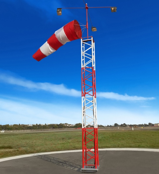
Image disclaimer: For identification and illustration only. It may show a product by another manufacturer and may not depict the exact item described; it is not a statement of any product’s quality, approval or performance. Third-party image and trademark rights belong to their owners. See full notice.
What Is It?
A Wind Cone Mast is the vertical structural support that holds the wind cone (windsock) at an elevated height, typically 6 to 10 metres above ground level. It provides a stable mounting platform that allows the wind cone to rotate freely to indicate wind direction. The mast is usually made from corrosion‑resistant materials such as galvanized steel, powder‑coated aluminium, or fibreglass. At the top of the mast is a swivel bearing or ring that allows the wind cone to rotate 360° with minimal friction. The mast may be designed as a frangible structure — meaning it will break away on impact to minimize damage to an aircraft — especially when installed near runways or taxiways. The mast also serves as a conduit for electrical wiring if the wind cone is internally illuminated.
Purpose & Function
The wind cone mast's purpose is to put the windsock where every pilot needs it — high enough to catch representative wind unaffected by ground-level turbulence, and positioned so it stays visible from the air and from the runway during approach, taxi, and takeoff. Because wind direction can shift with altitude and proximity to buildings or terrain, mounting height directly affects how trustworthy the visual cue is; a windsock too low or too sheltered can show misleading wind information at exactly the moment a pilot needs it most.
The mast's frangible design serves a second, equally important purpose: since the wind cone often sits close to a runway or taxiway precisely so pilots can see it clearly, that same proximity means it must break away harmlessly if struck, rather than becoming a rigid obstacle that could damage an aircraft during an excursion or wingtip strike.
Where Is It Used?
Installed at all airfields, heliports, and military landing zones that require visual wind indication. Typically placed near the runway threshold, at the centre of the airfield, or at a location visible from both the approach and the apron. The mast is also used at fire stations, emergency helipads, offshore platforms, and any location where a windsock is needed. The mast height is chosen to ensure the wind cone is visible above obstructions (buildings, trees, other structures) and is within the pilot's line of sight during final approach.
Installation & Location
The mast is founded on a concrete base, with a frangible coupling fitted where the installation falls within a runway strip, taxiway strip, or other frangibility-sensitive area, so the structure breaks away safely on impact. Siting follows the same clearance logic as the windsock it carries: positioned clear of buildings, trees, and other obstructions, and kept within the obstacle-limitation surface for the runway so it doesn't itself become a hazard to aircraft. Height is selected so the sock remains visible above surrounding obstructions and within a pilot's normal line of sight on final approach, and where illumination is fitted, the cable routing, whether an external floodlight supply or an internal conduit to a hoist-frame head fitting, is built into the mast design and installation from the outset.
How Does It Work?
The wind cone mast functions as a rigid vertical support that elevates the wind cone to a height where it is visible to pilots. The mast is anchored to a concrete foundation or ground plate, with guy wires (if needed) for additional stability in high‑wind areas. At the top, a low‑friction swivel bearing or ring allows the wind cone to rotate freely in response to the wind. The mast may be hollow to allow internal wiring for illuminated windsocks. In frangible designs, the mast is constructed with a breakaway coupling or from a material that will shear on impact, reducing the risk of serious damage to an aircraft that may strike it. The mast is also designed to withstand wind loads, ice accumulation, and corrosion, ensuring reliable long‑term operation.
System Architecture & Control Logic
The mast carries no sensors, controllers, or decision-making of its own — it is a passive structural member that two separate systems simply share. At the top, the swivel bearing and cone assembly respond mechanically to wind with no electronics involved at all. Where the installation is illuminated, a feeder cable from the same ALCMS-controlled lighting circuit that serves other airfield lighting is routed up through the hollow mast interior as a passive conduit run, with no junction box, sensor, or control point along the way, and terminates at the lamp housing near the swivel bearing at the top. The mast's only "control logic" is the frangible coupling's mechanical fail-safe: it is engineered to shear once impact force exceeds a fixed threshold, a purely passive structural response with no sensor, signal, or system decision behind it.
ALCMS / CCR Loop → Feeder Cable → Mast Interior (passive conduit) → Lamp Housing at Top
Normal Operation vs. Impact
SHEARS
Physical Construction
The mast is a vertical structural pole fabricated from galvanized steel, powder-coated aluminium, or fibreglass, sized in height and diameter to hold the wind cone assembly at the standard elevation while resisting wind loading up to its rated capacity, with guy wires used on taller or higher-wind-rated installations for additional stability. The base is set into a concrete foundation, ground plate, or flange mount appropriate to the site soil conditions, and where the mast is sited near runways or taxiways, a frangible coupling or shear-pin base is incorporated so the structure breaks away cleanly on aircraft impact rather than posing a rigid obstruction. At the top of the mast, a sealed ball bearing or low-friction swivel ring allows the wind cone to rotate a full 360° with minimal resistance, ensuring the cone tracks changing wind direction accurately. Where internal illumination is required, the mast is fabricated as a hollow tube with an internal conduit run from the base to the lamp fixture near the top, keeping wiring protected from weather and mechanical damage. All external surfaces and fasteners are corrosion-resistant, given the mast's permanent, unsheltered outdoor siting.
Technical Parameters
| Parameter | Typical Value |
|---|---|
| Material | Galvanized steel, powder‑coated aluminium, or fibreglass |
| Height | 6–10 m (20–30 ft) above ground level |
| Diameter | 50–100 mm (2–4 in) depending on material |
| Mounting Type | Concrete base, ground plate, or flange mount |
| Swivel Bearing | Sealed ball bearing or low‑friction ring (360° rotation) |
| Frangible Option | Breakaway coupling or shear‑pin design (optional) |
| Wind Load Rating | Up to 200 km/h (125 mph) with guy wires |
| Protection Class | Corrosion‑resistant coating (galvanized or powder‑coat) |
| Internal Conduit | Hollow mast for wiring (internal illumination) |
Electrical Requirements
| Requirement | Typical Value |
|---|---|
| Applicability | Electrical requirements apply only where the mast carries wiring for an illuminated wind cone; non-illuminated masts have no electrical function |
| Circuit Type | Simple on/off lighting circuit fed from the same ALCMS-controlled circuit as other airfield lighting (not a CCR intensity-stepped loop) |
| Cable Routing | Feeder cable enters at the mast base and runs as a passive conduit through the hollow mast interior to the lamp housing at the top — no junction box or sensor along the run |
| Feed Cable | Direct-burial rated feeder, run underground in duct to the local distribution point |
| Circuit Protection | Dedicated circuit breaker at the distribution point |
| Insulation Resistance | ≥ 50 MΩ (megger test, cable-to-ground) |
| Earthing/Grounding | Mast structure and lamp housing bonded to airfield earth grid |
| Fault Protection | Circuit breaker trip / visual and insulation-resistance inspection (on/off circuit, no loop-level fault detection) |
Applicable Standards
ICAO Annex 14
Windsock mast height and visibility requirements
FAA AC 150/5345-27
Specification for wind cone mast assemblies
CAA CAP 168
Licensing of Aerodromes — windsock and mast siting requirements
Installation Requirements
Foundation & Frangible Coupling Setting
CivilSet the concrete base, ground plate, or flange mount to suit site soil conditions, fitting the frangible coupling or shear-pin base where the site is frangibility-sensitive.
Siting & Obstacle Clearance Check
CivilConfirm the mast height and position keep it within the obstacle-limitation surface for the runway and clear of buildings, trees, and other obstructions.
Guy Wire Rigging (Where Fitted)
MechanicalRig and tension guy wires on taller or higher-wind-rated installations for the additional stability the design calls for.
Swivel Bearing Fitting
MechanicalFit the sealed ball bearing or low-friction swivel ring at the mast top so the wind cone can rotate a full 360° with minimal resistance.
Internal Conduit Wiring (Illuminated Masts)
ElectricalWhere internal illumination is required, run the conduit from the base to the lamp fixture near the top, keeping wiring protected from weather and mechanical damage.
Corrosion Protection Verification
MechanicalConfirm all external surfaces and fasteners are corrosion-resistant, given the mast's permanent, unsheltered outdoor siting.
Handover Sign-off
DocumentationRecord foundation position, guy wire tensioning, and internal wiring route as-built before the mast is accepted for commissioning.
Testing & Commissioning
Foundation & Anchor Bolt Torque Check
Pre-AcceptanceConfirm foundation curing is complete and anchor bolts are torqued to specification before the mast is accepted for service.
Frangible Coupling Verification
Pre-AcceptanceConfirm the frangible coupling meets design shear tolerances and is correctly fitted before the site is finally backfilled.
Vertical Alignment/Plumb Check
Pre-AcceptanceVerify the mast is plumb within tolerance using a spirit level or theodolite before final sign-off.
Guy Wire Tension Check
Pre-AcceptanceWhere fitted, confirm guy wires are tensioned evenly to specification and anchor points are secure.
Swivel Bearing Free-Rotation Check
Functional TestConfirm the bearing at the mast head allows the windsock or ring assembly to rotate freely without binding.
Internal Wiring Insulation & Continuity Test
Pre-EnergisationFor illuminated masts, megger-test internal wiring and verify continuity from the junction box to the mast head before energisation.
Structural Rating Documentation Review
Final AcceptanceConfirm the as-built mast height, wind loading, and material certification match the design specification before handover.
Documentation & As-Built Sign-off
Final AcceptanceRecord foundation, alignment, and bearing test results alongside as-built position in the commissioning dossier for handover.
Inspection & Maintenance
Swivel Bearing Lubrication & Function Check
Semi-annualLubricate the sealed ball bearing or low-friction ring and confirm free 360° rotation, since a stiff bearing gives a false wind direction reading.
Frangible Coupling / Shear-Pin Inspection
AnnualWhere a breakaway coupling or shear-pin design is fitted, check for corrosion or fatigue and replace on schedule so the mast still fails safely on impact.
Corrosion & Coating Inspection
AnnualInspect the galvanized, powder-coated, or fibreglass finish for chips, corrosion, or UV degradation and touch up or recoat as needed.
Guy Wire Tension Check
AnnualWhere guy wires are fitted for the higher wind-load rating, check tension and anchor condition to confirm the mast still meets its rated wind loading.
Structural Base & Foundation Inspection
AnnualCheck the concrete base, ground plate, or flange mount for cracking, settlement, or corrosion that could compromise mast stability.
Internal Conduit & Wiring Check
AnnualWhere the mast is hollow for internal illumination wiring, inspect for chafing, corrosion, or moisture pooling inside the conduit.
Vertical Alignment Check
Semi-annualConfirm the mast remains plumb, since a leaning mast skews the windsock's apparent wind direction reading.
Cable & Power Connection Inspection
AnnualExamine supply wiring and connectors at the mast base for corrosion or loose terminations, a common cause of intermittent light or sensor failure.
Common Field Issues
Corrosion and Rust
Masts are exposed to rain, salt spray, and chemicals. Galvanized steel can corrode over time, especially at the base and welded joints. Regular inspection and repainting or replacement of corroded sections is essential.
Swivel Bearing Seizure
Dust, moisture, and lack of lubrication can cause the swivel bearing to seize, preventing the wind cone from aligning with the wind. Regular cleaning and lubrication (or bearing replacement) is critical.
Frangible Coupling Fatigue
In frangible mast designs, the breakaway coupling can become brittle due to weather and fatigue. Regular inspection and replacement of the coupling (every 5–7 years) is recommended to ensure breakaway performance.
Troubleshooting Guide
Mast Leaning or Out of Vertical Alignment
Wind Cone Not Rotating Freely at the Masthead
Visible Corrosion or Coating Failure on the Mast Surface
Mast Vibrating Excessively or Generating Noise in Wind
No Illumination at the Wind Cone (Internally Lit Types)
Failure Modes & Root Causes
Frangible Coupling Fatigue
Swivel Bearing Seizure
Corrosion / Coating Breakdown
Foundation Settlement / Structural Misalignment
Guy Wire / Fastener Loosening
Internal Illumination Wiring Fault
Safety & Operational Notes
Working at Height
Personnel SafetyMast access for the swivel bearing, sock, or illumination wiring is typically 6 to 10 metres above ground; use fall-arrest equipment and a stable access platform, and avoid climbing during high wind, given the mast is designed to be an exposed, unshielded structure.
Frangibility Not to Be Defeated
MechanicalNever substitute the frangible coupling with a rigid fitting or over-torque it during installation or repair; the coupling must still shear cleanly on aircraft impact under the frangibility requirement for masts sited within a runway or taxiway strip.
Electrical Isolation on Illuminated Masts
Electrical SafetyWhere the mast carries wiring for an internally illuminated wind cone, de-energise and verify zero energy at the circuit feed before working inside the mast or at the wiring conduit, since the mast doubles as a cable route.
Lightning Exposure
Personnel SafetyAs the tallest structure in its immediate area, the mast is a lightning attraction point; avoid working at or near the top during an electrical storm, and confirm grounding continuity is intact after any strike.
Airside Work Coordination
OperationalWork on a mast sited within the obstacle-limitation surfaces or movement area requires ATC/airside coordination and a NOTAM for the period the wind indicator is out of service, with vehicle and personnel movement kept clear per the aerodrome's safety management procedures.
FOD Control at the Base
OperationalKeep tools, fasteners, and hardware accounted for at all times when working at height on or around the mast, since dropped items at this height present both a FOD and a personnel-safety hazard.
Restore to Compliant State
ComplianceConfirm the sock rotates freely, the mast is plumb, and (where illuminated) the circuit is verified before closing out the work and cancelling the associated NOTAM.
Engineering & Expert Notes
Bearing Friction Increases Before the Cone Stops Moving
MaintenanceA worn swivel bearing makes the cone under-respond to gusty, rapidly shifting wind well before it seizes outright, and a sluggish cone can mislead a pilot about actual conditions more dangerously than an obviously stuck one; test free rotation under light wind rather than confirming only that the cone moves at all.
A Standing Mast Doesn't Confirm an Intact Frangible Point
MechanicalAn impact light enough not to break the mast can still fatigue the frangible coupling without leaving visible damage; inspect the frangible point on its standard cycle regardless of how sound the mast looks overall.
Inspect Internal Wiring at Flex Points, Not Just at the Light Fixture
ElectricalWind-induced sway over years chafes internal wiring for illuminated cones at flex points inside the mast, well away from the fixture itself; check cable routing along the mast's length at overhaul rather than only inspecting the fixture end.
Lift the Base Collar to Check for Hidden Corrosion
InspectionCorrosion at the base-to-foundation interface is often concealed by a decorative collar or grout line and missed by an external visual pass; lift or look underneath the collar during inspection rather than relying on what's visible from a walk-by.
Remove Informal Bracing That Defeats the Frangible Design
ComplianceA wobbly mast sometimes gets an informal guy-wire or rigid brace added in the field to fix the symptom, which defeats the mast's intended frangible behaviour; flag and remove any non-standard bracing found during inspection rather than leaving it in place.
Log Any Windsock Substitution Against the Site's Original Spec
DocumentationA windsock swapped for a different size or weight during a parts shortage changes the wind speed at which it reaches full extension, altering what the indication actually means to a pilot; log any substitution against the site's original specification rather than treating windsocks as interchangeable.
Frequently Asked Questions
Short answers about wind cone masts: height, frangibility, materials, lighting, standards, maintenance and common faults.
Q1What is a wind cone mast?
A wind cone mast is the vertical structure that holds a wind cone (windsock) at an elevated height, typically 6 to 10 m above ground level. A swivel bearing or ring at the top lets the wind cone rotate 360° with minimal friction to show wind direction.
Q2How tall should a wind cone mast be?
Typically 6–10 m (20–30 ft), chosen so the wind cone is high enough to catch representative wind unaffected by ground-level turbulence and stays visible above buildings and trees from the air and the runway. A windsock that is too low or sheltered gives an untrustworthy reading.
Q3Where are wind cone masts installed?
At airfields, heliports and military landing zones, near the runway threshold, at the airfield centre or where they are visible from both the approach and the apron. They are also used at fire stations, emergency helipads and offshore platforms.
Q4Does a wind cone mast need to be frangible?
Where the mast falls within a runway strip, taxiway strip or another frangibility-sensitive area, it is fitted with a breakaway coupling or shear-pin design so it breaks away on impact and minimises damage to an aircraft. The mast must also stay within the obstacle-limitation surface so it does not become a hazard.
Q5What is a wind cone mast made of?
Galvanised steel, powder-coated aluminium or fibreglass, 50–100 mm in diameter, on a concrete base, ground plate or flange mount. Masts can carry guy wires and are rated for winds up to about 200 km/h (125 mph) with guy wires.
Q6Can a wind cone mast carry lighting?
Yes. The mast may be hollow so feeder cable can run inside to an illuminated windsock. This is a simple on/off lighting circuit from the ALCMS-controlled airfield lighting circuit, not a CCR intensity-stepped loop, with a dedicated breaker at the distribution point.
Q7Which standards apply to wind cone masts?
The main references are ICAO Annex 14, FAA AC 150/5345-27 (wind cone mast assemblies) and CAA CAP 168 for windsock and mast siting requirements. Always verify the current edition and your national authority's requirements.
Q8How often should a wind cone mast be inspected?
Typically semi-annually for swivel bearing lubrication and function, and annually for frangible coupling or shear-pin inspection, corrosion and coating inspection, guy wire tension checks and structural base and foundation inspection. Your approved maintenance programme takes precedence.
Q9Why is my windsock not rotating freely?
The swivel bearing has probably seized from corrosion, water ingress or lack of lubrication. Test rotation by hand at the masthead, inspect the housing for corrosion, moisture or debris, then clean and re-lubricate or replace the bearing assembly. A stiff bearing gives a false wind direction.
Q10Why is the mast leaning or out of vertical?
Likely causes are foundation settlement, a partially sheared frangible coupling or impact damage. Check vertical alignment with a level or plumb line, inspect the coupling or shear pin and the base for settlement or heave, then re-level and re-secure.
Related Components
Go Beyond the Component. Understand the Complete AGL System.
You have explored the component. Now understand how it works within the complete Airfield Ground Lighting system.
Learn AGL from fundamentals to design, installation, testing, photometry, commissioning, maintenance and troubleshooting through structured technical training at Precision AGL Academy.
Build practical knowledge. Understand the circuit. Read the standards. Troubleshoot with confidence.
Your next step in AGL starts here.
Need expert guidance on wind cone mast selection or installation?
Precision AGL Academy provides advice on mast height, frangible design, and corrosion protection for wind cone support structures.
Follow the Academy
Important Notice, Disclaimer & Limitation of Liability
Please read before relying on any content on this page.
- Purpose and intended users. This page on Wind Cone Mast is an independent educational and informational reference for competent, suitably trained and authorised airfield ground lighting (AGL) and aerodrome electrical personnel. It is not professional engineering, legal or regulatory advice, and using it does not create any professional or client relationship.
- Safety. Work on series circuits, constant current regulators (CCRs), isolating transformers, cables, connectors and lighting equipment can be fatal. Always apply the aerodrome’s permit-to-work and isolation/LOTO procedures, prove dead, use correctly rated instruments and PPE, and follow the manufacturer’s instructions. Nothing here authorises work on live equipment or the bypassing of any safety device or interlock.
- Aviation operations. Nothing here authorises installation, modification, energisation, adjustment, return to service, a change of operating category (CAT I/II/III), a NOTAM or any aerodrome certification or approval decision. These rest with the aerodrome operator, the air navigation service provider and the competent regulator.
- Specifications, ratings and typical values. Descriptions, parameters, ratings, dimensions, photometric values, wattages, service lives, maintenance tasks and intervals, failure modes, certifications (for example CE, FCC, UL or IEC marks) and part or type designations are general, typical and indicative. They may not match any particular product, make, model or version, and they are not a datasheet, design, specification, selection, sizing, procurement or acceptance criterion. The manufacturer’s current documents, the approved design and the project specification prevail.
- Standards and regulations. References to ICAO, FAA, IEC, IEEE, ISO, BIS, DGCA and other standards are paraphrased summaries for orientation only. They may be incomplete or out of date, and standards are revised from time to time. Consult the current official editions. Following this content does not guarantee compliance with any law, standard or regulatory approval, and the regulator’s requirements always prevail.
- No warranty. Content is provided “as is” and “as available”, without warranty of any kind, express or implied, including accuracy, completeness, currency or fitness for a particular purpose. Real installations differ in design, equipment make and model, age and condition.
- Limitation of liability. To the fullest extent permitted by applicable law, Precision AGL Academy, Precision AGL Solutions and their owners, authors and contributors are not liable for any injury, death, loss, damage, downtime, penalty or regulatory consequence, whether direct or indirect, arising from the use of, reliance on, or inability to use this content. Nothing in this notice excludes or limits any liability that cannot lawfully be excluded or limited.
- Independence, brands and no endorsement. This is an independent publication. It is not affiliated with, sponsored by or endorsed by ICAO, the FAA, the IEC, DGCA, AAI, any airport, regulator, supplier or equipment manufacturer. Third-party names, product designations, standard designations and trademarks (including Megger®, Siemens, Eaton, Crouse-Hinds, ADB SAFEGATE, Fluke, ABB and Honeywell) belong to their respective owners and are used only for identification and description. Mention of a brand, product or supplier is not a recommendation, and we do not sell, supply or quote for any component described.
- Images and third-party content. Images and illustrations are shown to help identify the type of component. They may show products of various manufacturers, may not depict the exact item described, and are not a statement about any product’s quality, approval or performance. Copyright and trademarks in third-party images, logos and photographs belong to their respective owners and are not claimed as ours. If you are a rights holder and want an image removed, replaced or credited, email precisionaglsolutions@gmail.com with the page address and we will act promptly.
- Training and services. Mentions of training, courses, consultation, advice, selection, installation, calibration or other support, including the “Learn…Certify” pathway, describe learning stages and are not an offer, quotation, tender or promise of any result. Contacting us or our replying creates no engagement or duty of care; an engagement exists only under a written agreement. We are not a regulator or certification body, and completing any course or reading this content is not a certification, accreditation or authorisation to work on any aerodrome.
- Copyright, privacy and corrections. © 2026 Precision AGL Academy. All rights reserved. Text, structure, compilations and diagrams may be viewed for personal reference and internal training only; any other copying, republication or commercial use needs our written permission. If you email, telephone or message us, we use your details only to respond and handle your matter, in line with applicable Indian law including the Digital Personal Data Protection Act, 2023; please do not send confidential or security-sensitive information. To display this page your browser requests fonts, icons and images from third-party servers, which receive your IP address and browser details under their own policies. Content is reviewed periodically with no obligation to update. To report an error, safety concern or rights issue, write to precisionaglsolutions@gmail.com.