Earthing Connector
A specialised connector used to terminate and bond earthing/grounding cables to earth pits, electrodes, equipment chassis, and structural steel in AGL systems. Designed for low‑resistance, corrosion‑resistant connections that provide a reliable path to earth for fault currents, lightning strikes, and electrostatic discharge.
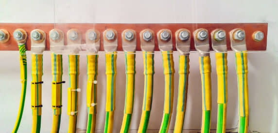
Image disclaimer: For identification and illustration only. It may show a product by another manufacturer and may not depict the exact item described; it is not a statement of any product’s quality, approval or performance. Third-party image and trademark rights belong to their owners. See full notice.
What Is It?
An Earthing Connector (also known as a grounding connector or earth clamp) is a specialised termination device used to establish a low‑resistance, permanent electrical connection between earthing/grounding conductors and earth electrodes, earth pits, equipment chassis, structural steel, and other grounding points in airfield ground lighting (AGL) systems. These connectors are critical for ensuring the safety and reliability of the electrical infrastructure, providing a safe path for fault currents, lightning strikes, and electrostatic discharge to dissipate into the earth.
Earthing connectors are available in a variety of configurations, including:
- Exothermic Welding Connectors: Permanent, high‑integrity connections formed by a molten copper alloy that fuses the conductor to the earth electrode, providing the lowest possible resistance and exceptional durability.
- Mechanical Clamps: Bolted or screw‑type clamps that provide a secure, removable connection for copper or aluminium conductors to earth rods, tapes, or bus bars.
- Compression Lugs: Crimp‑type lugs similar to cable lugs, but specifically designed for earthing applications, often with larger stud holes and corrosion‑resistant plating.
- Clamp‑on Connectors: Quick‑connect clamps for temporary or test earthing connections, allowing easy attachment and removal.
The connector is selected based on the earthing conductor type (bare copper, tinned copper, or copper‑clad steel), the earth electrode type (rod, plate, or tape), the required current rating, and the environmental conditions. Proper selection and installation are essential to maintain a low earth resistance (typically ≤ 10 Ω for AGL systems) and ensure personnel and equipment safety.
Purpose & Function
The earthing connector is what turns a designed earthing system, on paper a network of electrodes and conductors sized to a target resistance value, into a physically continuous path that fault current can actually follow. Every junction in that network, from electrode to conductor to equipment chassis, is only as good as its weakest connection, so a single poorly made or corroded connector can raise the overall earth resistance well above the design figure without any visible sign of failure elsewhere in the system. Choosing a connector suited to the specific conductor and electrode materials, exothermic welding for a permanent bond versus a mechanical clamp for a serviceable one, is what keeps that resistance low over the working life of the installation rather than only at the time of commissioning.
Where Is It Used?
Earthing connectors are used throughout the airfield wherever grounding connections are required, including:
- Earth Pit Terminations: Connecting the main earthing conductor to the earth electrode (rod, plate, or grid) inside the earth pit.
- Equipment Chassis Bonding: Bonding AGL equipment (CCRs, distribution panels, junction boxes, light fixtures) to the earthing system for safety and lightning protection.
- Structural Steel Bonding: Connecting earthing conductors to airfield structures (masts, poles, buildings) to provide a low‑impedance path to earth.
- Lightning Protection Systems: Terminating lightning down‑conductors to the earthing grid.
- Isolating Transformer Earthing: Connecting the transformer's earthing terminal to the earthing system.
- Test Points: Providing accessible points for measuring earth resistance using an earth tester.
The connectors are designed for both buried and above‑ground installations, with materials and plating selected to resist corrosion in the specific soil conditions (e.g., high salinity, acidity, or alkalinity). They are typically rated for fault currents ranging from a few hundred amperes to over 100 kA for lightning protection.
Installation & Location
The connector is installed at the point where an earthing or bonding conductor meets its electrode, equipment chassis, or structural steel, typically inside an earth pit, inspection well, or equipment enclosure where it can be inspected or tested without major excavation. Exothermic connections are made using a graphite mould that positions the conductor and electrode precisely before the weld is fired, producing a permanent joint that is then left exposed within the pit for future inspection rather than backfilled directly over the weld. Mechanical clamps and compression lugs are torqued to the manufacturer's specification and, where installed below grade, protected with an anti-corrosion compound or wrap suited to the local soil conditions. Test-point connectors are sited so they remain accessible at finished grade, usually within a marked earth pit cover, allowing periodic earth resistance testing without disturbing the permanent connections elsewhere in the system.
How Does It Work?
An earthing connector provides a secure, low‑resistance electrical path between the earthing conductor and the earth electrode or equipment. Its design ensures a reliable connection that can carry fault currents without overheating or degrading. The functional principles vary by connector type:
- Exothermic Welding: A molten copper alloy is poured into a graphite mould that surrounds the conductor and electrode. The alloy fuses to both metals, creating a homogeneous, gas‑tight connection with resistance lower than the conductor itself. This is the most reliable and durable method, with no galvanic corrosion risk.
- Mechanical Clamps: A bolted or screw‑type clamp compresses the conductor against the electrode or bus bar. The connection relies on the contact pressure to achieve low resistance. Regular torque checks are required to maintain the connection.
- Compression Lugs: The earthing conductor is crimped into a lug, which is then bolted to the earth electrode or bus bar. The lug is typically tin‑plated or silver‑plated to resist corrosion.
- Clamp‑on Connectors: A spring‑loaded or screw‑type clamp allows rapid connection and disconnection, typically used for temporary earthing or testing.
Regardless of the type, the key performance requirements are:
- Low Contact Resistance: The connection must have a resistance of a few milliohms (or less) to ensure effective fault current dissipation.
- Corrosion Resistance: The materials must withstand the soil chemistry, moisture, and temperature variations without significant degradation.
- Mechanical Strength: The connection must withstand mechanical stress from ground movement, vibration, and thermal expansion without loosening or breaking.
- Fault Current Capacity: The connector must be rated for the maximum expected fault current without melting or arcing.
System Architecture & Control Logic
The earthing connector sits outside the constant current series circuit entirely — it forms part of the protective earthing and bonding system, not the ALCMS/CCR-controlled lighting loop, and it carries no lighting current in normal operation. Because it plays no role in the current the CCR regulates, its condition is invisible to the loop-level fault detection that flags an open circuit or a voltage anomaly on the series loop: a loosened clamp, a degraded compression lug, or a corroded exothermic weld produces no signal the control system can see. The connector's job is purely to hold contact resistance low enough (a few milliohms) that, if a fault or a lightning strike does occur, the resulting current has a genuinely low-impedance path to the electrode rather than through equipment enclosures or personnel. Its integrity is therefore verified independently of the lighting control system, through periodic earth resistance testing and visual/torque inspection of the connection, rather than through anything the ALCMS reports.
Series Circuit Loop (ALCMS / CCR-controlled) runs independently of the Earthing Connector's Fault Path
Bonding Method vs. Permanence
Earthing Conductor
Must reach the electrode, bus bar, or equipment chassis at low resistance
Molten Copper Alloy Fuses the Joint
Conductor and electrode become one homogeneous connection
Permanent, Gas-Tight, No Galvanic Risk
Resistance lower than the conductor itself; nothing to loosen
Bolted or Crimped Connection
Relies on contact pressure rather than fusion
Removable, But Needs Upkeep
Requires periodic torque checks to maintain low resistance
Fault Current Capacity and Long-Term Corrosion Resistance Both Depend on Which Bonding Method Was Chosen at Installation
Physical Construction
Physical form follows connection type. An exothermic connector is not a hardware part at all in the finished state but a fused mass of copper alloy: a graphite mould clamps around the conductor and electrode, a measured charge of copper oxide and aluminium powder is ignited inside it, and the resulting exothermic reaction produces molten copper that flows around both members and solidifies into a single, permanent, weld‑like joint with no mechanical interface to loosen or corrode. Mechanical clamps and clamp‑on connectors, by contrast, are bolted assemblies—typically a bronze, brass, or tinned‑copper body split into two halves that close around the conductor and electrode under one or more bolts, generating high contact pressure at the mating surfaces. Compression lugs follow the same crimp‑barrel‑and‑bolt‑pad construction as a standard cable lug, but with larger stud holes and heavier plating to suit the earthing conductor sizes and outdoor exposure typical of AGL earthing points.
Technical Parameters
| Parameter | Typical Value |
|---|---|
| Material | Copper (EC grade), bronze, brass, or aluminium (with bi‑metallic options) |
| Plating/Coating | Tin, silver, nickel, or bare (with anti‑oxidant compound) |
| Conductor Size Range | 6mm² to 300mm² (AWG 10 to 600 MCM) — varies by connector type |
| Earth Rod Diameter Compatibility | 12mm to 25mm (½" to 1") — for clamp‑on connectors |
| Stud Hole Diameter | M6 to M20 (6mm to 20mm) — for bolted connections |
| Fault Current Rating (1 sec) | 10kA to 100kA (depending on size and material) |
| Resistance (connection) | ≤ 50 µΩ (exothermic weld); ≤ 100 µΩ (mechanical clamp) |
| Operating Temperature | -40°C to +105°C (copper); up to +200°C (silver‑plated) |
| Protection Class (installed) | IP68 (buried) or IP65 (above‑ground with enclosure) |
| Standards | IEC 62561, IEEE 80, BS 7430, FAA AC 150/5340‑30 (grounding/counterpoise) |
Electrical Requirements
| Requirement | Typical Value |
|---|---|
| Circuit Position | Bonding point between fixture/equipment body and airfield earth grid |
| Fault Current Rating (1 sec) | 10kA to 100kA (sized to grid fault-current design) |
| Connection Resistance | ≤ 50 µΩ (exothermic weld); ≤ 100 µΩ (mechanical clamp) |
| Earth Loop Resistance (system target) | Per site earthing design, typically ≤ 10 Ω at test point |
| Continuity Requirement | Verified bonding continuity, no series-connected joints relying solely on paint/coating contact |
| Isolation from Series Loop | Earth path kept separate from primary series circuit conductors |
Applicable Standards
IEC 62561
Lightning protection system components (including earthing connectors)
IEEE 80
Guide for safety in AC substation grounding
BS 7430
Code of practice for earthing (UK standard)
FAA AC 150/5340‑30
Design and Installation Details for Airport Visual Aids — grounding and counterpoise requirements
Installation Requirements
Exothermic Mould Positioning
FitPosition the conductor and electrode precisely in the graphite mould before firing the weld, since an exothermic joint cannot be corrected or redone once the reaction completes.
Accessible Placement
FitLocate the connector inside an earth pit, inspection well, or equipment enclosure where it can be inspected or tested without major excavation, rather than backfilled directly over.
Clamp & Lug Torque
FitTorque mechanical clamps and compression lugs to the manufacturer's specification, confirming high contact pressure is achieved at the mating surfaces.
Below-Grade Corrosion Protection
FitProtect connections installed below grade with an anti-corrosion compound or wrap suited to the local soil conditions.
Test-Point Accessibility
FitSite test-point connectors so they remain accessible at finished grade, usually within a marked earth pit cover, allowing periodic earth resistance testing without disturbing permanent connections elsewhere.
Contact Resistance Check
ElectricalMeasure contact resistance at the completed connection before backfill, confirming it clears the acceptable maximum for the joint type.
Pre-Energisation Sign-off
DocumentationRecord connector type, location, and resistance reading as-built before backfill, since these are not inspectable once the site is closed.
Testing & Commissioning
Continuity Test
Pre-EnergisationVerify low-resistance continuity through the connector between conductor and electrode or structure before backfill.
Contact Resistance Test
Pre-EnergisationMeasure resistance across the clamped or bolted joint with a micro-ohmmeter, flagging any connection above the acceptable threshold.
Corrosion & Bimetallic Compatibility Check
Pre-EnergisationConfirm connector material is compatible with both the conductor and the structure it bonds to, avoiding galvanic corrosion at dissimilar-metal joints.
Torque Verification
Pre-EnergisationTorque bolted connectors to the manufacturer's specification and mark each joint to confirm it has been checked.
Documentation & As-Built Sign-off
Final AcceptanceRecord continuity and contact resistance readings alongside connector locations in the commissioning dossier for handover.
Inspection & Maintenance
Earth Resistance Test
AnnualTest earth resistance with a 3-pole or 4-pole earth tester and confirm it stays at or below 10 Ω, since undetected high-resistance connections compromise safety.
Mechanical Clamp Torque Check
AnnualRe-torque bolted clamps and verify lock washers or thread-locking compound are intact, since thermal cycling and vibration loosen connections over time.
Corrosion Inspection
AnnualCheck the connection interface for corrosion and reapply anti-oxidant compound, since exposure to moisture and soil chemicals steadily raises resistance.
Earth Pit Drainage Check
AnnualInspect earth pits for waterlogging and improve drainage where needed, since standing water accelerates corrosion and degrades the connection.
Exothermic Weld Inspection
AnnualVisually inspect exothermic welds for porosity or weakness that could indicate an improper mould placement or weld procedure during installation.
Ground Movement Check
Semi-annualCheck buried connections for fractures caused by ground movement, frost heave, or nearby vehicle traffic, and confirm flexible connectors and strain relief are still effective.
Common Field Issues
Corrosion of Connection Interface
Earthing connectors are exposed to moisture and soil chemicals. Corrosion at the connection interface increases resistance, reducing the effectiveness of the earthing system. Use appropriate plating (tin, silver, or nickel), apply anti‑oxidant compound, and consider exothermic welding for critical connections.
Insufficient Contact Pressure (Mechanical Clamps)
Bolted clamps can loosen over time due to thermal cycling or vibration, increasing contact resistance. Use torque wrenches, lock washers, and thread‑locking compound. Schedule periodic torque checks as part of maintenance.
Galvanic Corrosion in Bi‑Metallic Connections
Connecting copper conductors to aluminium electrodes or steel structures can cause galvanic corrosion. Use bi‑metallic connectors (e.g., copper‑to‑aluminium lugs) or apply a protective coating and anti‑oxidant compound.
Inadequate Earth Pit Drainage
Waterlogged earth pits can accelerate corrosion and degrade the connection. Ensure proper drainage and consider using stainless steel or bronze connectors in wet conditions.
Fracture from Mechanical Stress
Ground movement, frost heave, or vehicle traffic can stress the connection, causing fractures or breakage. Use flexible connectors or provide adequate strain relief for buried connections.
Incorrect Exothermic Weld Procedure
Improper mould placement, inadequate cleaning, or insufficient weld material can result in a weak or porous weld, increasing resistance. Follow the manufacturer's procedure strictly and use the correct mould and weld material for the conductor size.
Failure to Test After Installation
Earth resistance should be tested after installation and periodically thereafter. Failure to test can leave undetected high‑resistance connections that compromise safety. Use an earth tester (3‑pole or 4‑pole method) to verify resistance ≤ 10 Ω.
Troubleshooting Guide
Earth Resistance Test Fails (>10 Ω)
Visible Corrosion at the Connector
Connection Loose or Showing Reduced Contact Pressure
Fracture or Break at a Buried Connector
Weak or Porous Exothermic Weld
Failure Modes & Root Causes
Corroded or Loose Connection
Connector Body Corrosion
Loosened Bolted Clamp
Fracture from Ground Movement
Weak or Porous Exothermic Weld
Safety & Operational Notes
Exothermic Welding Hazards
Personnel SafetyWear appropriate face, eye, and hand protection when performing an exothermic weld, keep the work area clear of flammable material, and allow the mould and weld to cool fully before handling.
Excavation & Buried Services
OperationalLocate and mark all buried services before excavating to expose an earthing connector, and hand-dig within the tolerance zone of the marked cable to avoid a strike on adjacent circuits or utilities.
Do Not Disturb an Active Earthing Path
Electrical SafetyConfirm that no fault current or lightning event is in progress and that the equipment served by this earthing point is de-energised where practical before breaking or remaking the connection.
Correct Torque & Weld Procedure
WorkmanshipTorque bolted clamps to the manufacturer's specified value and follow the exothermic weld procedure exactly, including mould selection and conductor cleaning, since a weak connection here defeats the earthing system.
Verify Earth Resistance After Work
Electrical SafetyPerform a 3-pole or 4-pole earth resistance test after any repair or reconnection to confirm the earthing point still meets its acceptable resistance limit before returning it to service.
Bedding & FOD Control
OperationalBed the connector properly and use strain relief or a flexible connector where ground movement is expected, and account for all tools and offcuts at the excavation to prevent foreign object debris on or near the movement area.
Restore to Compliant State
ComplianceDo not leave an earthing connection loose, corroded, or unverified; record the resistance test result and confirm the connector is fully backfilled and protected before closing out the work.
Engineering & Expert Notes
Earth Resistance Drifts With Soil Moisture, Not Just Corrosion
ElectricalA resistance reading taken during a dry season can look markedly worse than the same point measured after rain, independent of any degradation at the connector; trend readings across seasons before concluding a connector itself has failed.
Exothermic Weld Quality Depends on Conductor Prep, Not Just the Mould
WorkmanshipAn exothermic weld made on a conductor that wasn't fully cleaned and dried can look visually sound yet have poor internal fusion; the weld's mechanical and electrical integrity depends as much on surface prep as on correct mould selection.
Bonding Network Is Only as Good as Its Weakest Point
DesignA single degraded earthing connector anywhere in a bonded network can raise the effective resistance for the whole system, not just the equipment nearest to it; test connectors as part of the network, not in isolation.
Lightning Events Warrant a Post-Strike Inspection, Even Without Reported Damage
OperationalA nearby lightning strike can degrade an earthing connection through arcing or thermal stress without leaving obvious external damage; schedule a resistance check after known strike events near the site rather than waiting for a routine cycle.
Dissimilar Metal Corrosion Applies to Earthing Too
WorkmanshipJoining copper earthing conductors directly to galvanized or aluminium structures without the correct bi-metallic transition accelerates galvanic corrosion at the earthing point just as it does at a cable lug; use the correct transition connector for the metals involved.
Visual Inspection Alone Cannot Confirm Earth Integrity
ComplianceA clamp or weld can look mechanically intact while corrosion has significantly raised its resistance internally; a 3-pole or 4-pole resistance test is the only reliable way to confirm the connection is still performing its function.
Related Components
Frequently Asked Questions
Short answers about earthing connectors: types, exothermic welds, resistance targets, standards and maintenance.
Q1What is an earthing connector?
An earthing connector, also known as a grounding connector or earth clamp, is a termination device that creates a low-resistance, permanent connection between earthing conductors and earth electrodes, earth pits, equipment chassis, structural steel and other grounding points. It gives fault currents, lightning strikes and electrostatic discharge a safe path to earth.
Q2What types of earthing connector are there?
Exothermic welding connectors (permanent fused joints), mechanical bolted or screw clamps (removable), compression lugs (crimped and bolted), and clamp-on connectors for temporary or test earthing.
Q3Why are exothermic welds considered the most reliable?
A molten copper alloy is poured into a graphite mould around the conductor and electrode, fusing them into one homogeneous, gas-tight joint with resistance lower than the conductor itself. There is no galvanic corrosion risk and nothing to loosen.
Q4Where are earthing connectors used?
At earth pit terminations, bonding of CCRs, distribution panels, junction boxes and light fixtures to the earthing system, structural steel bonding to masts and poles, lightning down-conductor terminations, isolating transformer earthing terminals, and test points for earth resistance measurement.
Q5What earth resistance is targeted in AGL systems?
Typically 10 Ω or less at the test point, though the site earthing design governs. Connection resistance itself should be 50 µΩ or less for an exothermic weld and 100 µΩ or less for a mechanical clamp.
Q6What are typical earthing connector specifications?
Materials are copper (EC grade), bronze, brass or aluminium (with bi-metallic options). Conductor range is 6 mm² to 300 mm² and fault current rating is 10 kA to 100 kA for 1 second depending on size and material. Protection is IP68 buried or IP65 above ground with enclosure.
Q7Which standards apply to earthing connectors?
The main references are IEC 62561 (lightning protection system components), IEEE 80, BS 7430 and FAA AC 150/5340-30 (grounding and counterpoise requirements). Always verify the current edition.
Q8How often should earthing connections be tested and inspected?
Annually: test earth resistance with a 3-pole or 4-pole tester, check clamp torque, corrosion, earth pit drainage and exothermic welds. Check buried connections for ground-movement damage semi-annually. Test again after any repair or reconnection.
Q9What are the common earthing connector problems?
Corrosion at the connection interface, loosening of mechanical clamps from thermal cycling or vibration, galvanic corrosion at bi-metallic connections, waterlogged earth pits, fractures from ground movement, frost heave or vehicle traffic, and weak or porous exothermic welds from incorrect procedure.
Q10What should I do if an earth resistance test fails?
A reading above 10 Ω is commonly caused by corrosion at the connector or a loose clamp. Test using the 3-pole or 4-pole method, inspect the connector, then clean or replace it, re-torque the clamp to specification and re-test until resistance is within the required limit.
Go Beyond the Component. Understand the Complete AGL System.
You have explored the component. Now understand how it works within the complete Airfield Ground Lighting system.
Learn AGL from fundamentals to design, installation, testing, photometry, commissioning, maintenance and troubleshooting through structured technical training at Precision AGL Academy.
Build practical knowledge. Understand the circuit. Read the standards. Troubleshoot with confidence.
Your next step in AGL starts here.
Need expert guidance on earthing connectors and grounding system design for your AGL project?
Precision AGL Academy provides advice on connector selection, exothermic welding, corrosion prevention, and earth resistance testing for reliable AGL earthing systems.
Follow the Academy
Important Notice, Disclaimer & Limitation of Liability
Please read before relying on any content on this page.
- Purpose and intended users. This page on Earthing Connector is an independent educational and informational reference for competent, suitably trained and authorised airfield ground lighting (AGL) and aerodrome electrical personnel. It is not professional engineering, legal or regulatory advice, and using it does not create any professional or client relationship.
- Safety. Work on series circuits, constant current regulators (CCRs), isolating transformers, cables, connectors and lighting equipment can be fatal. Always apply the aerodrome’s permit-to-work and isolation/LOTO procedures, prove dead, use correctly rated instruments and PPE, and follow the manufacturer’s instructions. Nothing here authorises work on live equipment or the bypassing of any safety device or interlock.
- Aviation operations. Nothing here authorises installation, modification, energisation, adjustment, return to service, a change of operating category (CAT I/II/III), a NOTAM or any aerodrome certification or approval decision. These rest with the aerodrome operator, the air navigation service provider and the competent regulator.
- Specifications, ratings and typical values. Descriptions, parameters, ratings, dimensions, photometric values, wattages, service lives, maintenance tasks and intervals, failure modes, certifications (for example CE, FCC, UL or IEC marks) and part or type designations are general, typical and indicative. They may not match any particular product, make, model or version, and they are not a datasheet, design, specification, selection, sizing, procurement or acceptance criterion. The manufacturer’s current documents, the approved design and the project specification prevail.
- Standards and regulations. References to ICAO, FAA, IEC, IEEE, ISO, BIS, DGCA and other standards are paraphrased summaries for orientation only. They may be incomplete or out of date, and standards are revised from time to time. Consult the current official editions. Following this content does not guarantee compliance with any law, standard or regulatory approval, and the regulator’s requirements always prevail.
- No warranty. Content is provided “as is” and “as available”, without warranty of any kind, express or implied, including accuracy, completeness, currency or fitness for a particular purpose. Real installations differ in design, equipment make and model, age and condition.
- Limitation of liability. To the fullest extent permitted by applicable law, Precision AGL Academy, Precision AGL Solutions and their owners, authors and contributors are not liable for any injury, death, loss, damage, downtime, penalty or regulatory consequence, whether direct or indirect, arising from the use of, reliance on, or inability to use this content. Nothing in this notice excludes or limits any liability that cannot lawfully be excluded or limited.
- Independence, brands and no endorsement. This is an independent publication. It is not affiliated with, sponsored by or endorsed by ICAO, the FAA, the IEC, DGCA, AAI, any airport, regulator, supplier or equipment manufacturer. Third-party names, product designations, standard designations and trademarks (including Megger®, Siemens, Eaton, Crouse-Hinds, ADB SAFEGATE, Fluke, ABB and Honeywell) belong to their respective owners and are used only for identification and description. Mention of a brand, product or supplier is not a recommendation, and we do not sell, supply or quote for any component described.
- Images and third-party content. Images and illustrations are shown to help identify the type of component. They may show products of various manufacturers, may not depict the exact item described, and are not a statement about any product’s quality, approval or performance. Copyright and trademarks in third-party images, logos and photographs belong to their respective owners and are not claimed as ours. If you are a rights holder and want an image removed, replaced or credited, email precisionaglsolutions@gmail.com with the page address and we will act promptly.
- Training and services. Mentions of training, courses, consultation, advice, selection, installation, calibration or other support, including the “Learn…Certify” pathway, describe learning stages and are not an offer, quotation, tender or promise of any result. Contacting us or our replying creates no engagement or duty of care; an engagement exists only under a written agreement. We are not a regulator or certification body, and completing any course or reading this content is not a certification, accreditation or authorisation to work on any aerodrome.
- Copyright, privacy and corrections. © 2026 Precision AGL Academy. All rights reserved. Text, structure, compilations and diagrams may be viewed for personal reference and internal training only; any other copying, republication or commercial use needs our written permission. If you email, telephone or message us, we use your details only to respond and handle your matter, in line with applicable Indian law including the Digital Personal Data Protection Act, 2023; please do not send confidential or security-sensitive information. To display this page your browser requests fonts, icons and images from third-party servers, which receive your IP address and browser details under their own policies. Content is reviewed periodically with no obligation to update. To report an error, safety concern or rights issue, write to precisionaglsolutions@gmail.com.