Pavement Temperature Sensor
A critical airfield sensor that measures the surface temperature of runways, taxiways, and aprons. Essential for winter maintenance operations, friction assessment, and ensuring safe aircraft operations in cold weather conditions.
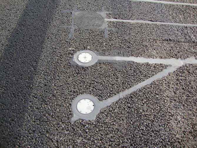
Image disclaimer: For identification and illustration only. It may show a product by another manufacturer and may not depict the exact item described; it is not a statement of any product’s quality, approval or performance. Third-party image and trademark rights belong to their owners. See full notice.
What Is It?
A Pavement Temperature Sensor is a specialized monitoring device installed in the surface of airfield pavements to measure the temperature of the asphalt or concrete surface. These sensors provide real-time data that is critical for:
- Winter maintenance decisions — determining when anti‑icing and de‑icing treatments are needed
- Friction assessment — understanding how temperature affects runway friction characteristics
- Pavement performance monitoring — tracking thermal stress and seasonal variations
- Flight planning — providing data for aircraft performance calculations (take‑off and landing distances)
- AGL equipment protection — helping to prevent damage from extreme pavement temperatures
Modern sensors use either contact (RTD, thermocouple) or non‑contact (infrared) technologies, with robust housings designed to withstand heavy aircraft loads and harsh environmental conditions.
Purpose & Function
The pavement temperature sensor exists because the same air temperature reading can correspond to very different runway surface conditions depending on solar loading, wind, and precipitation history, and it is the surface, not the air above it, that determines when ice actually forms. Feeding real, measured pavement temperature into winter maintenance decisions lets ground crews time anti-icing and de-icing treatments to when they are actually needed rather than on a fixed schedule or a conservative worst-case assumption, reducing both the risk of an untreated icy surface and the cost of treating pavement that did not need it. The same reading also has value beyond winter operations, since surface temperature directly affects the friction values used in landing distance and braking action assessments.
Where Is It Used?
Pavement temperature sensors are installed at strategic locations across the airfield to provide comprehensive thermal monitoring:
- Runways — at multiple points along the length (touchdown zone, mid‑point, and end) to capture thermal gradients
- Taxiways — to monitor pavement conditions for aircraft ground movement
- Apron and parking stands — to support de‑icing operations and ground handling
- Instrumented pavements — integrated with weather stations and friction measurement systems
- Remote airfields — where manual temperature monitoring is impractical
Data from these sensors is typically integrated into the airport’s weather observation system, ALCMS, or winter maintenance management platform for automated alerting and decision support.
Installation & Location
Contact sensors are set flush into the pavement surface at each monitoring point — typically the touchdown zone, mid-point, and far end of the runway, plus key taxiway and apron locations — with the probe body seated in a cored hole and bedded in a thermally conductive grout so it reads the true pavement temperature rather than an air gap. Signal cable runs from the probe through a small conduit stub to a roadside or shoulder-mounted junction box, then in duct back to a remote terminal unit or the airport weather station. Non-contact infrared units are instead mounted above the pavement on a pole or gantry with a clear, unobstructed view of the surface being measured, positioned clear of the aircraft movement area and any frangibility requirements that apply to fixed structures near the runway.
How Does It Work?
Pavement temperature sensors operate using one of the following principles:
- Contact Sensors (RTD / Thermocouple): A resistive temperature detector (RTD) or thermocouple is embedded in a metallic probe that is in direct contact with the pavement surface. The probe is installed flush with the pavement, and the sensor measures the temperature of the material. These provide high accuracy and fast response times.
- Infrared (IR) Sensors: A non‑contact sensor measures the infrared radiation emitted by the pavement surface. It is mounted above the pavement (e.g., on a pole or gantry) and measures surface temperature without physical contact. This method is less invasive but can be affected by atmospheric conditions and surface contamination.
- Wireless / IoT Sensors: Many modern sensors include wireless communication (LoRa, ZigBee, cellular) to transmit data to a central collection point, reducing installation complexity and enabling remote monitoring.
The sensor outputs standardised signals (e.g., 4‑20 mA, 0‑10 V, digital (MODBUS, SDI‑12)) that are read by a data logger or directly by the airport’s monitoring system. Calibration is performed to ensure accurate readings across the expected temperature range.
System Architecture & Control Logic
The pavement sensor itself is a passive measurement point; the control logic lives in the Runway Weather Information System (RWIS) it feeds. Embedded sensors report pavement surface and sub-surface temperature — and on combined sensors, surface state and freeze-point depressant concentration — over a wired loop to a field processor, which polls each sensor at a set interval and packages the readings for transmission to the central RWIS server. The server compares readings against forecast and threshold data to generate a freezing/frost risk assessment, which is displayed to airfield operations and can trigger a deicing or anti-icing response; sensor dropout or an out-of-range reading is flagged as a data-quality fault so operators don't mistake a failed sensor for confirmed dry pavement.
Sensor → Field Processor → RWIS Server → Risk Assessment → Operations Display
Measurement & Signal Path
Physical Construction
A contact probe (RTD or thermocouple) is a compact, stainless-steel or corrosion-resistant sensor head set into a flush-mounted housing that seats within the pavement structure, load-rated to withstand full aircraft wheel loading without disturbing the surrounding surface. The sensing element sits close to the exposed top face for a fast, representative reading of pavement skin temperature, with the housing gasket-sealed and potted internally to achieve an IP67/IP68 rating against water and de-icing fluid ingress. An infrared variant instead mounts above the pavement on a small elevated bracket or pole, aimed down at the surface with no physical contact, trading installation simplicity for a slightly lower accuracy and a need for a clear, unobstructed sightline. Signal cabling — typically twisted-pair for 4-20 mA or MODBUS/SDI-12 output — runs from the sensor through a sealed conduit to a nearby junction box, then on to a remote power supply or data logger, with the underground run protected against pavement loading the same way as other in-ground AGL cabling.
Technical Parameters
| Parameter | Typical Value |
|---|---|
| Sensor Type | RTD (PT100), Thermocouple (Type K/T), or Infrared |
| Temperature Range | -40°C to +85°C (-40°F to +185°F) |
| Accuracy | ±0.3°C (RTD) or ±1°C (IR) |
| Response Time | < 10 seconds (contact), < 1 second (IR) |
| Output Signals | 4‑20 mA, 0‑10 V, MODBUS, SDI‑12 |
| Operating Temperature | -40°C to +85°C |
| Protection Class | IP67 / IP68 (contact probes) |
| Load Capacity | > 100,000 kg (wheel load for flush‑mount probes) |
| Supply Voltage | 12‑36 VDC or 100‑240 VAC (power supply unit) |
| Mounting Type | Flush-mounted in pavement, or elevated (IR) |
| Cable Length | Typically 5‑30 m to junction box |
Electrical Requirements
| Requirement | Typical Value |
|---|---|
| Circuit Position | Standalone powered sensor, embedded or surface-mounted in pavement |
| Supply Voltage | 12‑36 VDC or 100‑240 VAC (via power supply unit) |
| Isolation | Sensor circuit isolated from mains via the PSU; signal output kept separate from power input |
| Earthing | Enclosure/cable armour bonded to local earth |
| Fault Protection | Surge protection on sensor and power lines (embedded sensors are lightning-exposed) |
Applicable Standards
ICAO Annex 3
Meteorological services — runway surface condition reporting
FAA AC 150/5200-30
Airport Field Condition Assessments and Winter Operations Safety
SAE ARP5533
Stationary Runway Weather Information System (In-Pavement)
WMO (CIMO)
Guide to meteorological instruments and methods of observation
Installation Requirements
Cored Hole & Grouting
CivilCore the mounting hole at each monitoring point and bed the contact probe body in thermally conductive grout so it reads true pavement temperature rather than an air gap.
Load-Rated Housing Fit
MechanicalSeat the flush-mounted, gasket-sealed housing so it withstands full aircraft wheel loading without disturbing the surrounding pavement surface.
Conduit Stub & Cable Route
ElectricalRun signal cable from the probe through a small conduit stub to a roadside or shoulder-mounted junction box, then in duct back to the remote terminal unit or weather station.
Infrared Unit Siting
MechanicalFor non-contact infrared units, mount above the pavement on a pole or gantry with a clear, unobstructed view of the surface, sited clear of the movement area and applicable frangibility requirements.
Signal Interface Termination
ElectricalTerminate the 4-20 mA or MODBUS/SDI-12 output at the junction box and confirm the interface is correctly wired to the data logger or remote terminal unit before energisation.
Pre-Commissioning Sign-off
DocumentationRecord probe position, cable route, and junction box location as-built before backfill or final fixing.
Testing & Commissioning
Insulation Resistance Test
Pre-EnergisationMegger-test the sensor cable and supply wiring before the probe is grouted or bolted into the pavement, confirming insulation resistance clears the acceptable minimum.
Sensor Calibration Verification
Pre-EnergisationCompare the RTD, thermocouple, or infrared sensor's reading against a calibrated reference thermometer across the expected temperature range, confirming accuracy is within specification.
Output Signal Verification
EnergisationConfirm the 4-20mA, 0-10V, MODBUS, or SDI-12 output signal is correctly received and scaled at the RWIS or control system before final connection.
Response Time Verification
EnergisationApply a step temperature change and confirm the sensor's response time meets its rated specification (typically under 10 seconds for contact probes, under 1 second for infrared).
Flush-Mount Load & Seal Verification
Final AcceptanceConfirm the flush-mounted probe meets its rated wheel-load capacity and that surface sealing prevents water or de-icing fluid ingress around the sensor face.
Documentation & As-Built Sign-off
Final AcceptanceRecord insulation resistance, calibration comparison, output signal, and response-time results alongside as-built sensor position in the commissioning dossier for handover.
Inspection & Maintenance
Calibration Check
AnnualVerify sensor accuracy against a reference thermometer or portable temperature probe placed adjacent to the sensor.
Pre-Winter Physical Inspection
Semi-annualInspect flush-mounted sensors for damage from snow plows or rubber removal operations before the winter season begins.
Seal & IP Rating Verification
AnnualCheck housing seals and cable glands for moisture ingress, especially after extreme weather events.
Cable & Connector Inspection
AnnualExamine cabling and connectors for corrosion or damage that could introduce reading errors.
Data Feed Latency Check
QuarterlyVerify network configuration and response times so winter maintenance systems receive timely, accurate readings.
Protective Cap & Housing Inspection
Semi-annualCheck protective caps and recessed housings for wear or displacement that could expose the sensor to damage.
Common Field Issues
Sensor Drift and Calibration Shift
Over time, RTD and thermocouple sensors can experience drift due to thermal cycling and mechanical stress. Regular calibration checks (annually) using a reference thermometer are essential to maintain accuracy. In the field, this is often done with a portable temperature reference probe placed adjacent to the sensor.
Mechanical Damage from Snow Plows
Flush‑mounted sensors are vulnerable to damage from snow removal equipment and runway rubber removal operations. Protective caps or recessed designs are recommended. Regular visual inspections and replacement of damaged sensors are critical before the winter season.
Moisture Ingress and Corrosion
The sensor housing and cable glands must be sealed against moisture. Water ingress can cause reading errors or complete failure. Regular inspection of seals and IP rating verification is recommended, especially after extreme weather events.
Data Integration Latency
When integrated with winter maintenance systems, data latency can affect the timeliness of de‑icing decisions. Ensuring proper network configuration and using fast‑response sensors (e.g., IR) can help reduce delays in data transmission.
Troubleshooting Guide
Readings Drift from a Reference Probe
Sensor Physically Damaged or Missing
Erratic or No Reading
Delayed Data Reaching the Winter Maintenance System
Failure Modes & Root Causes
Sensor Element Drift
Physical Damage from Ground Equipment
Housing Seal Failure
Data Latency to Winter Maintenance System
Safety & Operational Notes
Circuit Isolation Before Servicing
Electrical SafetyDe-energise and lock out the sensor's power and signal circuit at the field cabinet before disconnecting or replacing the sensor or its cabling.
Airside Work Coordination
OperationalAny work on a pavement-embedded sensor within the movement area requires ATC/airside coordination and a NOTAM where the work will obstruct or close part of the pavement.
FOD Control During Installation or Repair
OperationalKeep tools, sealant offcuts, and coring debris accounted for at all times when the pavement is open, and sweep the area before reopening it to traffic.
Pavement Cutting/Coring Safety
MechanicalWear eye and hearing protection when cutting or coring pavement to install or replace a sensor, and confirm the location is clear of buried cables or conduit before cutting.
Winter Maintenance Data Continuity
OperationalConfirm the winter maintenance system has a valid alternate data source or is placed in manual mode before taking a pavement temperature sensor offline during winter operations.
Engineering & Expert Notes
Embedment Depth Trades Response Speed for Durability
DesignA sensor set very close to the pavement surface reads temperature changes faster but is more exposed to mechanical stress from traffic and snow-clearing equipment. Match embedment depth to how the winter maintenance system actually uses the data, not just to the manufacturer's minimum spec.
A Slow Drift Is Easy to Miss Against a Single Calibration Point
TroubleshootingComparing a sensor's reading against a single reference check at commissioning won't catch a sensor that drifts gradually over years of thermal cycling. Trend readings against a nearby reference sensor or portable calibrated probe periodically, rather than relying on a one-time acceptance test.
A Failed Sensor Is an Operational Problem Before It's a Maintenance One
OperationalWinter maintenance decisions can depend directly on this sensor's reading, so a fault needs to trigger a fallback data source or manual mode immediately, not wait for the next scheduled maintenance visit. Build the sensor's health status into the winter operations dashboard, not just the asset management system.
Resurfacing Work Is the Highest-Risk Moment for This Sensor
ReliabilityPavement milling and overlay work is a common cause of accidental sensor damage or cable severance, often discovered only when the sensor goes offline weeks later. Flag embedded sensor locations clearly on any resurfacing work package, not just on the original as-built drawings.
Cable Run Length Affects Signal Integrity More Than Expected
ElectricalLong cable runs from a pavement-embedded sensor back to the field cabinet can introduce measurable signal degradation or noise pickup, particularly where the run parallels high-current cabling. Verify signal quality at the cabinet end after any nearby cabling work, even if the sensor itself wasn't touched.
Sealant Choice Around the Sensor Matters Long-Term
DurabilityThe sealant used to reinstate the pavement around a sensor needs to handle the same freeze-thaw and de-icing chemical exposure as the surrounding pavement, or it becomes the first thing to fail and let moisture reach the sensor and cabling. Specify sealant to the pavement's actual service environment, not a generic patching compound.
Frequently Asked Questions
Short answers about pavement temperature sensors: why they matter, types, accuracy, installation, standards, maintenance and common faults.
Q1What is a pavement temperature sensor?
A pavement temperature sensor is a monitoring device installed in an airfield pavement surface to measure asphalt or concrete temperature. Its real-time data supports winter maintenance, friction assessment, pavement monitoring, flight planning and protection of AGL equipment.
Q2Why measure pavement temperature instead of air temperature?
The same air temperature can mean very different surface conditions depending on solar loading, wind and precipitation history, and it is the surface, not the air, that determines when ice forms. Measured pavement temperature lets crews time anti-icing and de-icing treatments to when they are needed.
Q3What types of sensor are used?
Contact sensors (RTD/PT100 or thermocouple) in a metallic probe set flush in the pavement, and infrared (IR) non-contact sensors mounted above the surface on a pole or gantry.
Q4How accurate is a pavement temperature sensor?
About ±0.3 °C for RTD and ±1 °C for IR, over −40 °C to +85 °C. Response time is under 10 seconds for contact probes and under 1 second for IR.
Q5Where are the sensors installed?
At the touchdown zone, mid-point and far end of runways, plus key taxiway and apron locations, and on instrumented pavements alongside weather stations and friction measurement systems. Contact probes sit in a cored hole bedded in thermally conductive grout so they read true pavement temperature.
Q6What outputs and supply does a sensor need?
Outputs are 4–20 mA, 0–10 V, Modbus or SDI-12 over typically 5–30 m of cable to a junction box, powered from 12–36 VDC or 100–240 VAC through a PSU. Surge protection on sensor and power lines matters because embedded sensors are lightning-exposed.
Q7Can a flush-mounted sensor take aircraft loads?
Yes. Flush-mount probes are rated above 100,000 kg wheel load with IP67/IP68 protection, though snow ploughs and rubber removal can still damage them.
Q8Which standards apply to pavement temperature sensors?
The main references are ICAO Annex 3, FAA AC 150/5200-30 (field condition assessments and winter operations), SAE ARP5533 (in-pavement runway weather information systems) and the WMO (CIMO) guide to meteorological instruments. Always verify the current edition and your national authority's requirements.
Q9How often should a pavement temperature sensor be maintained?
Typical intervals are quarterly for data feed latency checks, semi-annual for pre-winter physical inspection and protective cap and housing inspection, and annual for calibration check against a reference thermometer, seal and IP rating verification and cable and connector inspection. Your approved maintenance programme takes precedence.
Q10Why do sensor readings drift from a reference probe?
RTD and thermocouple drift from thermal cycling and mechanical stress. Compare against a portable reference probe placed beside the sensor across a range of temperatures, recalibrate, or replace the sensor if it cannot be brought back within tolerance.
Q11Why is a sensor damaged, missing or giving erratic or no readings?
Damage or a missing sensor usually follows a strike from snow removal or rubber removal equipment, so replace it, fit a protective cap or recessed design and inspect before winter. Erratic or no readings usually mean water ingress into the housing or cable glands.
Related Components
Go Beyond the Component. Understand the Complete AGL System.
You have explored the component. Now understand how it works within the complete Airfield Ground Lighting system.
Learn AGL from fundamentals to design, installation, testing, photometry, commissioning, maintenance and troubleshooting through structured technical training at Precision AGL Academy.
Build practical knowledge. Understand the circuit. Read the standards. Troubleshoot with confidence.
Your next step in AGL starts here.
Need expert guidance on pavement temperature sensor selection or installation?
Precision AGL Academy provides advice on sensor placement, calibration, and integration with winter maintenance and ALCMS systems.
Follow the Academy
Important Notice, Disclaimer & Limitation of Liability
Please read before relying on any content on this page.
- Purpose and intended users. This page on Pavement Temperature Sensor is an independent educational and informational reference for competent, suitably trained and authorised airfield ground lighting (AGL) and aerodrome electrical personnel. It is not professional engineering, legal or regulatory advice, and using it does not create any professional or client relationship.
- Safety. Work on series circuits, constant current regulators (CCRs), isolating transformers, cables, connectors and lighting equipment can be fatal. Always apply the aerodrome’s permit-to-work and isolation/LOTO procedures, prove dead, use correctly rated instruments and PPE, and follow the manufacturer’s instructions. Nothing here authorises work on live equipment or the bypassing of any safety device or interlock.
- Aviation operations. Nothing here authorises installation, modification, energisation, adjustment, return to service, a change of operating category (CAT I/II/III), a NOTAM or any aerodrome certification or approval decision. These rest with the aerodrome operator, the air navigation service provider and the competent regulator.
- Specifications, ratings and typical values. Descriptions, parameters, ratings, dimensions, photometric values, wattages, service lives, maintenance tasks and intervals, failure modes, certifications (for example CE, FCC, UL or IEC marks) and part or type designations are general, typical and indicative. They may not match any particular product, make, model or version, and they are not a datasheet, design, specification, selection, sizing, procurement or acceptance criterion. The manufacturer’s current documents, the approved design and the project specification prevail.
- Standards and regulations. References to ICAO, FAA, IEC, IEEE, ISO, BIS, DGCA and other standards are paraphrased summaries for orientation only. They may be incomplete or out of date, and standards are revised from time to time. Consult the current official editions. Following this content does not guarantee compliance with any law, standard or regulatory approval, and the regulator’s requirements always prevail.
- No warranty. Content is provided “as is” and “as available”, without warranty of any kind, express or implied, including accuracy, completeness, currency or fitness for a particular purpose. Real installations differ in design, equipment make and model, age and condition.
- Limitation of liability. To the fullest extent permitted by applicable law, Precision AGL Academy, Precision AGL Solutions and their owners, authors and contributors are not liable for any injury, death, loss, damage, downtime, penalty or regulatory consequence, whether direct or indirect, arising from the use of, reliance on, or inability to use this content. Nothing in this notice excludes or limits any liability that cannot lawfully be excluded or limited.
- Independence, brands and no endorsement. This is an independent publication. It is not affiliated with, sponsored by or endorsed by ICAO, the FAA, the IEC, DGCA, AAI, any airport, regulator, supplier or equipment manufacturer. Third-party names, product designations, standard designations and trademarks (including Megger®, Siemens, Eaton, Crouse-Hinds, ADB SAFEGATE, Fluke, ABB and Honeywell) belong to their respective owners and are used only for identification and description. Mention of a brand, product or supplier is not a recommendation, and we do not sell, supply or quote for any component described.
- Images and third-party content. Images and illustrations are shown to help identify the type of component. They may show products of various manufacturers, may not depict the exact item described, and are not a statement about any product’s quality, approval or performance. Copyright and trademarks in third-party images, logos and photographs belong to their respective owners and are not claimed as ours. If you are a rights holder and want an image removed, replaced or credited, email precisionaglsolutions@gmail.com with the page address and we will act promptly.
- Training and services. Mentions of training, courses, consultation, advice, selection, installation, calibration or other support, including the “Learn…Certify” pathway, describe learning stages and are not an offer, quotation, tender or promise of any result. Contacting us or our replying creates no engagement or duty of care; an engagement exists only under a written agreement. We are not a regulator or certification body, and completing any course or reading this content is not a certification, accreditation or authorisation to work on any aerodrome.
- Copyright, privacy and corrections. © 2026 Precision AGL Academy. All rights reserved. Text, structure, compilations and diagrams may be viewed for personal reference and internal training only; any other copying, republication or commercial use needs our written permission. If you email, telephone or message us, we use your details only to respond and handle your matter, in line with applicable Indian law including the Digital Personal Data Protection Act, 2023; please do not send confidential or security-sensitive information. To display this page your browser requests fonts, icons and images from third-party servers, which receive your IP address and browser details under their own policies. Content is reviewed periodically with no obligation to update. To report an error, safety concern or rights issue, write to precisionaglsolutions@gmail.com.