Visibility Sensor
A precision optical instrument that measures atmospheric visibility and Runway Visual Range (RVR), providing critical data for low-visibility operations and airfield safety. Available in forward scatter, transmissometer, and backscatter configurations.
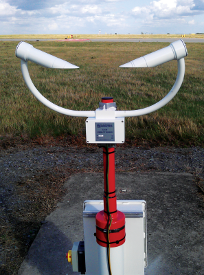
Image disclaimer: For identification and illustration only. It may show a product by another manufacturer and may not depict the exact item described; it is not a statement of any product’s quality, approval or performance. Third-party image and trademark rights belong to their owners. See full notice.
What Is It?
A Visibility Sensor is a meteorological instrument used to measure atmospheric visibility, specifically the Meteorological Optical Range (MOR) and Runway Visual Range (RVR). It is a critical component of airfield weather systems, providing data that determines the operational status of the aerodrome, especially for low-visibility procedures (CAT I, II, III). Visibility sensors operate on the principle of light extinction or scattering: either measuring the attenuation of a light beam over a known distance (transmissometer) or measuring the scattering of light from a small volume of air (forward scatter sensor). The sensor outputs a visibility value in metres or kilometres, which is used by ATC, pilots, and automated systems for safe operations.
Purpose & Function
A visibility sensor exists to give the airfield an objective, continuously updated read on how far a pilot can actually see through the atmosphere, which is the single factor that most directly gates low-visibility operations. Because MOR and RVR values are what set CAT I/II/III minima, an airport's ability to keep operating safely in fog, haze, rain, or snow depends on trusting this number rather than a subjective estimate from a single observer at one point on the field.
The sensor's role becomes most critical exactly when conditions are worst: as visibility drops toward the threshold where an approach can no longer legally continue, accurate, real-time data is what allows ATC and pilots to make that go/no-go call with confidence, rather than discovering the runway environment isn't visible only during the final seconds of an approach.
Where Is It Used?
Installed at airfields as part of the meteorological observation system, typically located near the touchdown zone of each runway, and sometimes at the mid‑point or stop end. Visibility sensors are used for RVR reporting, which is mandatory for precision approach runways. They are also used at remote airstrips, heliports, and offshore platforms where visibility data is essential for flight safety. The sensors are mounted on masts or poles at a height of approximately 2.5 metres above the runway surface, in accordance with ICAO recommendations.
Installation & Location
Mounted on a mast or pole beside the runway strip at each required measurement point, typically the touchdown zone, with additional units at the mid-point and stop end on precision-approach runways, set at approximately 2.5 m above the runway surface in line with ICAO guidance. The sensor's transmitter and receiver (or the forward-scatter sample volume) are aligned along the anticipated line of sight so the reading is representative of the visibility a pilot would experience, and the mast is positioned clear of the obstacle-free zone at the mandated lateral offset from the runway edge. Power and data cabling run underground in duct back to the AWOS/RVR processing cabinet, and the optical heads are orientated to minimise direct low-sun glare, which can otherwise skew scatter-based readings.
How Does It Work?
A forward scatter visibility sensor emits a pulse of infrared or visible light into a small sampling volume of air. A receiver, positioned at a specific scatter angle (typically 35° or 42°), measures the amount of light scattered by atmospheric particles (aerosols, fog, rain, snow). The scattered light intensity is proportional to the extinction coefficient, which is then converted into MOR (Meteorological Optical Range) using the Koschmieder relationship. Transmissometers, on the other hand, use a separate transmitter and receiver separated by a known baseline (typically 30 to 75 metres); the attenuation of the light beam directly yields the visibility. The sensor outputs digital or analogue signals to the weather processing system, which calculates RVR using ambient light and background luminance corrections.
System Architecture & Control Logic
Where a runway has visibility sensors at more than one point, the system's real decision logic sits above the individual sensors, in the AWOS processor that combines them: it selects the controlling value — normally the lowest MOR/RVR among the fitted positions relevant to the operation — rather than reporting each sensor's reading in isolation, since a single obscured section of runway is enough to limit the approach regardless of what the other positions show. Each sensor also continuously self-monitors its own optical path: window contamination, condensation, or heater failure can degrade a reading without an obvious fault, so most units run heated optics and a contamination-check routine, reporting that health status to the processor alongside the raw measurement so a fouled sensor can be down-weighted or excluded rather than silently pulling the controlling value in the wrong direction. From there, the same processor layer that handles RVR calculation distributes the controlling value onward to ATC displays and METAR/ATIS reporting, and — on integrated sites — offers it as an input the ALCMS can use when recommending or auto-selecting a runway lighting intensity step.
Two Ways to Measure the Same Thing
Physical Construction
A visibility sensor is built around either a forward-scatter optical head, with transmitter and receiver arms angled toward a common sample volume, or a transmissometer configuration with transmitter and receiver units mounted a fixed, calibrated baseline distance apart. The optical housings are weatherproof enclosures, typically aluminium or composite construction rated to IP66/IP67, with heated lens hoods or windows to prevent condensation, frost, or precipitation from degrading the optical path. The sensor arms or transmitter/receiver towers are mounted on a rigid pole or frame set at the standard reference height, engineered to hold precise optical alignment against wind loading and vibration, since drift between the transmitter and receiver directly affects measurement accuracy. Internal electronics for signal processing are housed in a sealed enclosure at the base of the mounting structure or integrated into the optical head itself, connected by shielded, weather-rated cable. Corrosion-resistant materials and fasteners are used throughout given the sensor's typically exposed siting close to the runway or in open terrain.
Technical Parameters
| Parameter | Typical Value |
|---|---|
| Measurement Range (MOR) | 10 m – 20,000 m (or 0.005 – 12 miles) |
| Accuracy (MOR) | ±10% (for MOR < 600 m), ±15% (for MOR ≥ 600 m) |
| Wavelength | 880 nm (infrared) or 550 nm (visible, photopic) |
| Scatter Angle (forward scatter) | 35° – 42° (typical) |
| Baseline (transmissometer) | 30 m, 75 m, or 150 m |
| Output Signal | 4–20 mA, 0–10V, RS-232, RS-485, SDI-12, or Ethernet |
| Mounting Height | 2.5 m above runway surface (ICAO) |
| Protection Class | IP66 / IP67 (weatherproof) |
| Operating Temperature | -40°C to +60°C |
Electrical Requirements
| Requirement | Typical Value |
|---|---|
| Power Supply | 100–240V AC, 50/60Hz (or 24V DC on remote-powered installations) |
| Power Consumption | ~50–150W, including optics/window heater load |
| Heater Elements | Integrated anti-icing/anti-condensation heaters on lens/window and transmitter or receiver housing |
| Signal/Data Cable | Shielded twisted-pair, RS-485, or Ethernet run to AWOS/ALCMS data logger |
| Surge Protection | Lightning and surge arrestors on both power and signal lines |
| Earthing/Grounding | Sensor housing and mounting mast bonded to airfield earth grid |
| Backup Power | UPS or battery backup recommended for continuous visibility reporting |
| Power Source | Dedicated circuit from AWOS power distribution panel or airfield electrical supply |
Applicable Standards
ICAO Annex 3
Meteorological service requirements for RVR and visibility reporting
FAA AC 150/5220-16
Airport weather observation systems (AWOS) requirements
WMO No. 8 (Guide to Instruments)
Visibility measurement instrument specifications
ICAO Doc 9328
Manual of Runway Visual Range Observing and Reporting Practices
Installation Requirements
Mast Foundation & Lateral Clearance
CivilSet the mast foundation clear of the obstacle-free zone at the mandated lateral offset from the runway edge.
Measurement Point Positioning
CivilSite sensors at each required measurement point — typically the touchdown zone, with additional units at mid-point and stop end on precision-approach runways.
Cable Route to Processing Cabinet
ElectricalRun power and data cabling underground in duct back to the AWOS/RVR processing cabinet.
Optical Alignment
MechanicalSet the sensor at approximately 2.5 m above the runway surface with the transmitter/receiver or sample volume aligned along the anticipated line of sight.
Baseline Distance Setting
MechanicalFor transmissometer configurations, confirm the transmitter and receiver units are set at the fixed, calibrated baseline distance the design requires.
Sun-Angle Orientation Check
MechanicalOrientate the optical heads to minimise direct low-sun glare, which can otherwise skew scatter-based readings.
Heated Lens Wiring
ElectricalTerminate the heated lens hood/window circuit so condensation, frost, or precipitation cannot degrade the optical path.
Pre-Energisation Sign-off
DocumentationRecord mast position, cable route, and optical alignment as-built for each measurement point before commissioning.
Testing & Commissioning
Insulation Resistance & Continuity Test
Pre-EnergisationMegger-test power cabling and verify signal cable continuity before the sensor is energised, ruling out faults introduced during installation.
Power-Up & Self-Diagnostics
EnergisationEnergise the sensor and confirm it passes its internal self-diagnostic routine with no fault codes before proceeding to calibration.
Forward-Scatter Calibration Check
Functional TestVerify the scatter measurement against a certified reference scatter plate or calibration standard at the specified scatter angle.
Transmissometer Baseline Alignment
Functional TestFor transmissometer types, confirm the transmitter and receiver baseline is correctly aligned and the beam path is free of obstruction.
MOR Accuracy Verification
Functional TestCompare the calculated Meteorological Optical Range against a reference instrument reading across the operating range.
Optics Cleanliness Check
Functional TestInspect and clean sampling volume optics, confirming contamination-compensation readings are within normal range after cleaning.
Communications & Output Interface Test
Final AcceptanceConfirm visibility values report correctly to the weather processing system at the specified reporting interval before handover.
Documentation & As-Built Sign-off
Final AcceptanceRecord calibration, alignment, and communications test results alongside as-built position in the commissioning dossier for handover.
Inspection & Maintenance
Calibration Verification
AnnualCheck sensor output against a certified reference instrument across the measurement range to confirm the ±10%/±15% MOR accuracy specification is still being met.
Optical Window Cleaning
MonthlyClean the forward-scatter or transmissometer optical windows, since dust, insects, or condensation on the optics directly skews visibility readings feeding low-visibility operations.
Sensor Alignment Check
AnnualConfirm the forward-scatter angle or transmissometer baseline alignment remains within tolerance, since drift here degrades measurement accuracy without an obvious fault indication.
Output Signal & Communication Link Test
Semi-annualConfirm the sensor's 4-20mA/0-10V/RS-485/SDI-12/Ethernet output reaches the AWOS or ALCMS correctly and without signal noise.
Heater / De-icing Function Check
AnnualTest any heating elements on the optical housing ahead of the icing season, since frost or ice on the sensor optics can cause false low-visibility readings.
Seal & Weatherproofing Inspection
AnnualCheck housing seals and gaskets for cracking or degradation and confirm the IP66/IP67 rating is still intact.
Mounting Height & Alignment Verification
AnnualConfirm the sensor remains at the ICAO-specified 2.5m mounting height above the runway surface, since ground settlement or resurfacing can shift this over time.
Cable & Connector Inspection
AnnualExamine signal and power wiring for corrosion or loose terminations, a common source of erratic or dropped-out readings.
Common Field Issues
Lens Contamination and Window Fouling
Dust, dirt, bird droppings, and de-icing fluids can accumulate on the optical windows, reducing signal strength and causing underestimation of visibility. Regular cleaning with lens-safe solutions and soft cloths is essential, especially during winter and high‑pollution periods.
Calibration Drift and Alignment
Electronic drift and mechanical misalignment (especially for transmissometers) can lead to measurement errors. Annual calibration using certified reference standards and optical alignment checks are required to maintain accuracy within ICAO tolerances.
Icing and Snow Accumulation
In cold climates, ice can form on the optical windows or the sensor housing, blocking the light path. Heated window options are available, but regular visual inspection and de-icing procedures are recommended to ensure uninterrupted operation.
Lightning and Power Surges
Sensors mounted on masts are susceptible to lightning strikes and voltage surges. Proper surge protection, grounding, and uninterruptible power supplies (UPS) are critical to prevent damage and data loss.
Troubleshooting Guide
One Sensor Excluded from the Controlling MOR/RVR Value
Reported Visibility Lower Than Actual Conditions
Transmissometer Reading Drifting Over Time
Optical Path Blocked by Ice or Snow
Sensor Offline or No Output After Storm Activity
Controlling Value Selection Appears Wrong at AWOS/ALCMS Level
Failure Modes & Root Causes
Optical Window Contamination
Transmissometer Baseline Misalignment
Heated Optics / Hood Failure
Calibration Drift
Lightning / Surge Damage
Safety & Operational Notes
Electrical Isolation Before Servicing
Electrical SafetyDe-energise the sensor's mains supply and the separate optics/window heater circuit before opening the transmitter or receiver housing, and verify zero energy before handling connectors.
Hot Surfaces from Heater Elements
Personnel SafetyAllow the integrated anti-icing/anti-condensation heaters on the lens/window and transmitter or receiver housing to cool before handling after active operation.
Airside Work Coordination
OperationalVisibility sensor sites are within or near the movement area for AWOS/ASOS integration; coordinate with ATC and raise a NOTAM where visibility reporting will be degraded or unavailable during the outage.
Optical Alignment Precision
OperationalWhichever measurement principle the unit uses, confirm alignment and signal strength against the manufacturer's procedure rather than by eye alone, since a subtly misaligned unit can still report plausible but inaccurate values.
Optics Cleanliness and Protection
OperationalCap or shield the optics from direct sunlight and dust ingress whenever the housing is open, since a contaminated or scratched window directly degrades reading accuracy.
PPE and Grounding
Personnel SafetyUse insulated tools on mains-powered connections and confirm the sensor housing bonding and grounding are intact before reconnecting supply.
Restore to Compliant State
ComplianceVerify sensor output against a reference or cross-check with an adjacent sensor before closing out the work, and cancel the associated NOTAM once reporting is confirmed within tolerance.
Engineering & Expert Notes
Window Fouling Biases Visibility Gradually, Not Suddenly
MaintenanceOptical window contamination degrades reported visibility gradually enough that it's easy to miss on a quick visual glance; schedule window cleaning to a defined interval rather than reacting only when a complaint comes in.
A Persistent Disagreement Between Technologies Is Diagnostic
VerificationWhere both a transmissometer and a forward-scatter sensor exist at the same location, a consistent disagreement between the two technologies points to a real calibration issue rather than simple sensor noise; treat cross-technology comparison as a diagnostic tool, not just a redundancy nicety.
Re-Verify Siting Against Nearby Lighting Changes
SitingNew lighting installed near the sensor after commissioning can bias the co-located ambient light measurement; re-check siting against nearby light sources periodically rather than assuming the original commissioning survey still holds.
Check Heater Cycling Behaviour, Not Just That It Turns On
TroubleshootingA defogging heater stuck in the on position can itself introduce a slight bias through localised heat shimmer in extreme cases, while simply confirming the heater powers up doesn't catch a cycling fault; verify the heater's on/off cycling behaviour specifically.
Validate Firmware Updates Against a Known Reference
ConfigurationAn algorithm update that recalculates visibility from raw scatter counts can shift reported values without any physical change at the sensor; validate readings against a known reference immediately after any firmware update rather than assuming continuity.
Tighten the Cleaning Cadence for Seasonal Insect Activity
MaintenanceBird and insect activity around sensor optics in certain seasons fouls the optics faster than the general maintenance calendar assumes; adjust the cleaning schedule seasonally rather than applying one fixed interval year-round.
Frequently Asked Questions
Short answers about visibility sensors: how they work, range, standards and maintenance.
Q1What is a visibility sensor?
A visibility sensor is a meteorological instrument that measures atmospheric visibility, specifically the Meteorological Optical Range (MOR), and supports Runway Visual Range (RVR) reporting as part of an airfield weather system.
Q2How does a forward-scatter visibility sensor work?
It emits a pulse of infrared or visible light into a small sampling volume of air. A receiver at a set scatter angle, typically 35° to 42°, measures the scattered light, which is converted into an extinction coefficient and then MOR.
Q3What is the measurement range of a visibility sensor?
Typically MOR from 10 m to 20,000 m, at an 880 nm infrared or 550 nm visible wavelength. Transmissometer baselines of 30 m, 75 m or 150 m are also used.
Q4Where is a visibility sensor mounted?
At airfields as part of the meteorological observation system, near the runway. The page gives a mounting height of 2.5 m above the runway surface (ICAO).
Q5What is the difference between a visibility sensor and an RVR sensor?
A visibility sensor measures MOR. An RVR system combines that with an ambient light sensor and the runway light intensity setting to report what a pilot can see of the runway lights.
Q6Which standards apply to visibility sensors?
The main references are ICAO Annex 3, ICAO Doc 9328, FAA AC 150/5220-16 and WMO No. 8 (Guide to Instruments).
Q7How often should a visibility sensor be maintained?
Monthly optical window cleaning, and annual calibration verification against a certified reference and alignment checks.
Q8What are the common problems with visibility sensors?
Window fouling from dirt, insects and de-icing fluids, calibration drift and misalignment, ice and snow accumulation in cold climates, and lightning or power surges on masts.
Related Components
Go Beyond the Component. Understand the Complete AGL System.
You have explored the component. Now understand how it works within the complete Airfield Ground Lighting system.
Learn AGL from fundamentals to design, installation, testing, photometry, commissioning, maintenance and troubleshooting through structured technical training at Precision AGL Academy.
Build practical knowledge. Understand the circuit. Read the standards. Troubleshoot with confidence.
Your next step in AGL starts here.
Need expert guidance on visibility sensor selection, installation, or calibration?
Precision AGL Academy provides advice on RVR system design, sensor placement, and compliance with ICAO and FAA requirements.
Follow the Academy
Important Notice, Disclaimer & Limitation of Liability
Please read before relying on any content on this page.
- Purpose and intended users. This page on Visibility Sensor is an independent educational and informational reference for competent, suitably trained and authorised airfield ground lighting (AGL) and aerodrome electrical personnel. It is not professional engineering, legal or regulatory advice, and using it does not create any professional or client relationship.
- Safety. Work on series circuits, constant current regulators (CCRs), isolating transformers, cables, connectors and lighting equipment can be fatal. Always apply the aerodrome’s permit-to-work and isolation/LOTO procedures, prove dead, use correctly rated instruments and PPE, and follow the manufacturer’s instructions. Nothing here authorises work on live equipment or the bypassing of any safety device or interlock.
- Aviation operations. Nothing here authorises installation, modification, energisation, adjustment, return to service, a change of operating category (CAT I/II/III), a NOTAM or any aerodrome certification or approval decision. These rest with the aerodrome operator, the air navigation service provider and the competent regulator.
- Specifications, ratings and typical values. Descriptions, parameters, ratings, dimensions, photometric values, wattages, service lives, maintenance tasks and intervals, failure modes, certifications (for example CE, FCC, UL or IEC marks) and part or type designations are general, typical and indicative. They may not match any particular product, make, model or version, and they are not a datasheet, design, specification, selection, sizing, procurement or acceptance criterion. The manufacturer’s current documents, the approved design and the project specification prevail.
- Standards and regulations. References to ICAO, FAA, IEC, IEEE, ISO, BIS, DGCA and other standards are paraphrased summaries for orientation only. They may be incomplete or out of date, and standards are revised from time to time. Consult the current official editions. Following this content does not guarantee compliance with any law, standard or regulatory approval, and the regulator’s requirements always prevail.
- No warranty. Content is provided “as is” and “as available”, without warranty of any kind, express or implied, including accuracy, completeness, currency or fitness for a particular purpose. Real installations differ in design, equipment make and model, age and condition.
- Limitation of liability. To the fullest extent permitted by applicable law, Precision AGL Academy, Precision AGL Solutions and their owners, authors and contributors are not liable for any injury, death, loss, damage, downtime, penalty or regulatory consequence, whether direct or indirect, arising from the use of, reliance on, or inability to use this content. Nothing in this notice excludes or limits any liability that cannot lawfully be excluded or limited.
- Independence, brands and no endorsement. This is an independent publication. It is not affiliated with, sponsored by or endorsed by ICAO, the FAA, the IEC, DGCA, AAI, any airport, regulator, supplier or equipment manufacturer. Third-party names, product designations, standard designations and trademarks (including Megger®, Siemens, Eaton, Crouse-Hinds, ADB SAFEGATE, Fluke, ABB and Honeywell) belong to their respective owners and are used only for identification and description. Mention of a brand, product or supplier is not a recommendation, and we do not sell, supply or quote for any component described.
- Images and third-party content. Images and illustrations are shown to help identify the type of component. They may show products of various manufacturers, may not depict the exact item described, and are not a statement about any product’s quality, approval or performance. Copyright and trademarks in third-party images, logos and photographs belong to their respective owners and are not claimed as ours. If you are a rights holder and want an image removed, replaced or credited, email precisionaglsolutions@gmail.com with the page address and we will act promptly.
- Training and services. Mentions of training, courses, consultation, advice, selection, installation, calibration or other support, including the “Learn…Certify” pathway, describe learning stages and are not an offer, quotation, tender or promise of any result. Contacting us or our replying creates no engagement or duty of care; an engagement exists only under a written agreement. We are not a regulator or certification body, and completing any course or reading this content is not a certification, accreditation or authorisation to work on any aerodrome.
- Copyright, privacy and corrections. © 2026 Precision AGL Academy. All rights reserved. Text, structure, compilations and diagrams may be viewed for personal reference and internal training only; any other copying, republication or commercial use needs our written permission. If you email, telephone or message us, we use your details only to respond and handle your matter, in line with applicable Indian law including the Digital Personal Data Protection Act, 2023; please do not send confidential or security-sensitive information. To display this page your browser requests fonts, icons and images from third-party servers, which receive your IP address and browser details under their own policies. Content is reviewed periodically with no obligation to update. To report an error, safety concern or rights issue, write to precisionaglsolutions@gmail.com.