ALL ABOUT AIRFIELD GROUND LIGHTING
The complete guide to understanding how an airport's visual lighting system works — from approach to runway, taxiway, electrical infrastructure, control, monitoring, testing and maintenance.
What Is Airfield Ground Lighting?
Airfield Ground Lighting (AGL) is the integrated system of visual aids, lighting equipment, electrical infrastructure, control systems and associated equipment used to provide visual guidance to aircraft during approach, landing, takeoff and movement on the aerodrome surface.
AGL is not simply a collection of lights. It is an engineered system involving light fixtures, electrical power, series circuits, Constant Current Regulators, isolating transformers, primary cables, secondary connections, connectors, control systems, monitoring, visual aids, signs, photometry, inspection and maintenance — all working together as one chain.
Understand how airport ground lighting systems, visual aids, electrical circuits and control equipment fit together in a typical airport layout.
AGL Visual Encyclopedia: What does a complete AGL airport layout look like
Why AGL Is Important
AGL has one primary purpose: to provide reliable visual guidance to pilots.
Approach Guidance
Helps establish visual reference during approach.
Landing Guidance
Provides runway threshold, edge, centerline and touchdown-related visual information.
Taxi Guidance
Helps pilots identify taxi routes and intersections.
Surface Safety
Provides visual information that supports safe movement on runways, taxiways and other movement areas.
The objective of AGL is not brightness alone. It is correct visual information, in the correct location, with the correct colour, intensity, distribution and reliability.
How an AGL System Is Organized
Every AGL installation, whatever its size, follows the same basic logic — from the airfield itself down through visual guidance, fixtures, electrical distribution, control and monitoring, to testing and maintenance.
Control System → CCR
Selects intensity steps and switches circuits on/off from the control tower or lighting control room.
Monitoring System → CCR / Series Circuit
Tracks circuit current, faults and operating status in real time.
PAPI / Signs / Other Visual Aids → Dedicated Arrangements
Run on their own dedicated electrical and control arrangements alongside the main series circuit.
Power flows out to the lights, control sits over the top, and the earthing network runs underneath: the whole system on one page.
AGL Visual Encyclopedia: What does a complete AGL system look like
Where AGL Is Used on an Airport
Approach Area
- Approach lighting systems
- Visual approach aids
- PAPI
- Associated guidance
Runway
- Runway edge lights
- Threshold lights
- Runway end lights
- Runway centreline lighting
- Touchdown zone lighting
- Other runway-specific visual aids
Taxiway
- Taxiway edge lights
- Taxiway centreline lights
- Stop bars
- Runway guard lights
- Taxiway guidance
Apron / Manoeuvring Areas
- Stand guidance
- Apron-related visual aids
- Illuminated signs
- Aircraft movement guidance
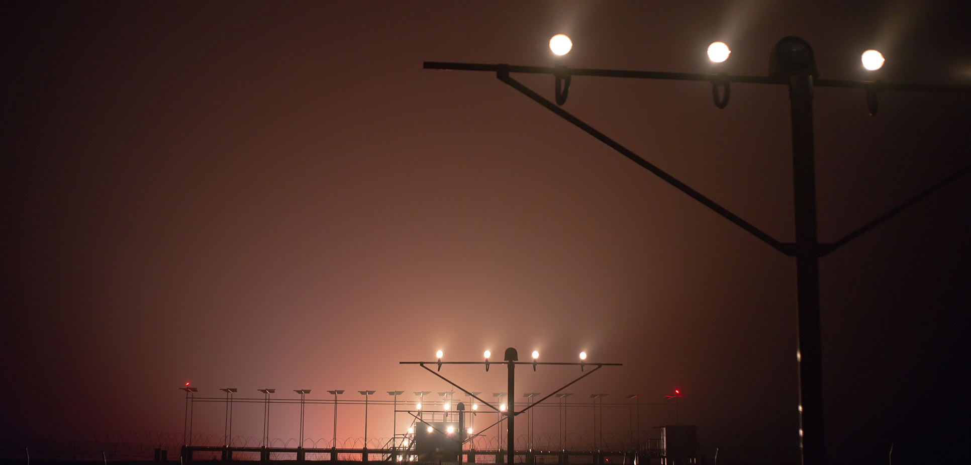
Approach → Runway → Taxiway → Apron — an aircraft passes through every AGL zone on a single arrival
Main AGL Components
Lighting Systems
- Approach Lights
- Runway Lights
- Taxiway Lights
- Stop Bars
- Runway Guard Lights
- PAPI
Electrical Systems
- CCR
- Series Circuit
- Isolating Transformers
- Primary Cable
- Secondary Cable
- Junction / Connection Systems
Connection Systems
- L-823 Plugs
- L-823 Receptacles
- Connector Kits
- Secondary Connectors
Signs
- Mandatory Signs
- Location Signs
- Direction Signs
- Information Signs
- Runway / Taxiway Signs
Control & Monitoring
- AGL Control System
- Remote Control
- Monitoring
- Fault Indication
- Intensity Selection
Testing
- Electrical Testing
- Insulation Resistance
- Continuity
- Transformer Testing
- Photometry
- Functional Testing
The finished unit as it stands on the airfield: a sealed light head, the mounting that fixes it to its base can, and the lead that connects it to power. The next entries take it apart.
AGL Visual Encyclopedia: A complete fixture
The AGL Electrical System
Unlike a conventional parallel lighting installation, many airport lighting circuits use series-circuit architecture, in which the lighting load is connected through isolating transformers and supplied from a Constant Current Regulator.
| Equipment | Main Function |
|---|---|
| CCR | Maintains controlled circuit current |
| Primary Cable | Carries the series-circuit supply |
| Isolating Transformer | Provides electrical isolation and transfers energy to the fixture |
| Secondary Cable | Connects transformer to fixture |
| Connector | Provides field connection |
| Fixture | Produces the required visual signal |
The CCR drives a constant current around the whole loop — every isolating transformer on it taps the same current
Understanding AGL Lighting Systems
Approach Lighting
Visual guidance leading toward the runway.
Runway Lighting
Defines runway geometry and operational areas.
Taxiway Lighting
Provides ground-movement guidance.
PAPI
Provides visual approach-slope information.
Airfield Signs
Provides mandatory, location, direction and information guidance.
Obstacle / Other Visual Aids
Supporting visual systems depending on aerodrome requirements.
Colour is the first thing a pilot reads on an airfield at night. White, yellow, green, red and blue each carry a fixed meaning, so the colour of a light says what kind of surface it marks and what to do next.
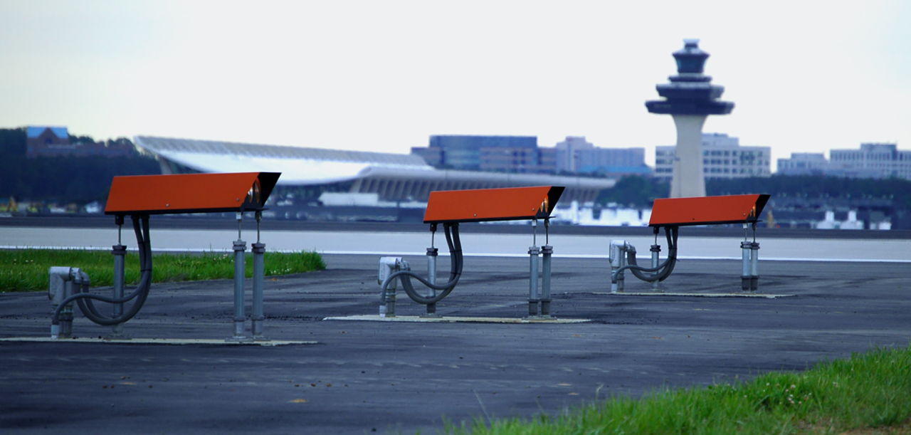
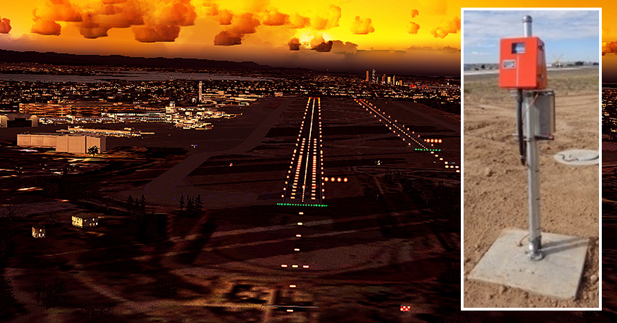
AGL Visual Encyclopedia: What does each AGL colour mean, and where is it used Complete taxiway lighting system Complete approach lighting configuration

AGL Control and Intensity
Why Multiple Intensity Steps?
LOW
MEDIUM-LOW
MEDIUM
HIGH
MAXIMUM
Command flows down from the control source; status and fault data flow back up

AGL Photometry
AGL photometry is the measurement and evaluation of the optical performance of airfield lighting equipment or installed lighting systems against applicable requirements.
Intensity
How much light is produced in the required direction.
Distribution
Where the light is directed and how it is distributed.
Colour
Whether the emitted light falls within the applicable chromaticity requirements.
Alignment
Whether the optical system is correctly oriented.
Intensity, colour and alignment are measured against the beam's design axis; distribution is mapped across the full beam pattern
Why Photometry Matters
A light can appear bright and still fail a photometric requirement.
Explore AGL PhotometryAGL Standards & Compliance
Annex 14 — Aerodromes
Applicable FAA AC 150/5340 and related specifications
Relevant Indian Standards for equipment and electrical requirements
Applicable electrical and equipment standards where specified
Applicable Indian regulatory, airport and project requirements
Ask what the regulator and the contract name, then choose by scope, and record the standard and its edition.
AGL Visual Encyclopedia: How do you choose the standard for an AGL item Standard comparison
AGL Testing, Inspection & Maintenance
Electrical
- Continuity
- Insulation resistance
- Circuit current
- Voltage
- Transformer testing
- Earth-fault investigation
Photometric
- Intensity
- Distribution
- Colour
- Alignment
- Photometric compliance
Mechanical
- Fixture condition
- Housing
- Mounting
- Sealing
- Connector condition
Operational
- CCR operation
- Intensity steps
- Control
- Monitoring
- Fault indications
The planned order of work on a scheduled visit — plan and permit, look while live, isolate, clean, inspect and test, then restore, verify and record, so wear is found and fixed before a light fails.
AGL Visual Encyclopedia: The preventive maintenance sequence
Common AGL Problems
Click a fault to see the areas most likely responsible.
One Light OFF
Possible Areas
- Fixture
- Secondary cable
- Transformer
- Connector
Multiple Lights OFF
Possible Areas
- Series circuit
- Primary cable
- CCR
- Circuit section
Entire Circuit OFF
Possible Areas
- CCR
- Earth fault
- Open circuit
- Short circuit
- Protection trip
Low Intensity
Possible Areas
- CCR output
- Circuit current
- Transformer
- Fixture
- Optical degradation
Flickering
Possible Areas
- Loose connection
- Transformer
- Fixture
- Cable
- CCR instability
High Leakage
Possible Areas
- Cable insulation
- Moisture
- Connector
- Transformer
Match the symptom to the likely places in the loop, then narrow the fault down by section with the circuit isolated.
AGL Visual Encyclopedia: How do you troubleshoot a series circuit
AGL From Design to Operation
This gives the subject a complete engineering lifecycle — from airport requirement through to ongoing inspection and maintenance.
Airport Requirement
Operational need is identified against the aerodrome's category and requirements.
System Design
Lighting layout, circuits and control philosophy are engineered.
Equipment Selection
Fixtures, CCRs, transformers, cables and signs are specified.
Procurement
Equipment is sourced against the approved specification.
Installation
Fixtures, cabling and equipment are installed on the airfield.
Electrical Testing
Continuity, insulation resistance and circuit checks are carried out.
Commissioning
The system is brought into service and verified against design intent.
Photometry
Intensity, distribution, colour and alignment are measured and verified.
Operation
The system enters day-to-day operational service.
Inspection & Maintenance
Ongoing electrical, photometric, mechanical and operational checks keep the system compliant.
The whole life of an AGL asset — from the decision to buy it, through years of service, to renewal or retirement.
AGL Visual Encyclopedia: The asset lifecycle
Explore the AGL Engineering Knowledge Hub
Fundamentals
Standards & Compliance
Runway, Taxiway & Approach Lighting
Surface Movement & Safety
PAPI
Electrical Engineering & Power
Photometry & Testing
Maintenance, Inspection & Safety
Resources, Documentation & Careers
Frequently Asked Questions About AGL
Quick answers about airfield ground lighting, from components and series circuits to photometry, standards and maintenance.
Q1What is Airfield Ground Lighting (AGL)?
Airfield Ground Lighting (AGL) is the integrated system of visual aids, lighting equipment, electrical infrastructure, control systems and associated equipment that gives aircraft visual guidance during approach, landing, takeoff and movement on the aerodrome surface. It is an engineered system, not just a collection of lights: fixtures, series circuits, Constant Current Regulators, isolating transformers, cables, connectors, control, monitoring, photometry, inspection and maintenance all work together as one chain.
Q2Why is AGL important for airport safety?
AGL exists to give pilots reliable visual guidance for approach, landing, taxiing and surface movement. The goal is not brightness alone but correct visual information in the correct location, with the correct colour, intensity, distribution and reliability.
Q3What are the main components of an AGL system?
The main components are the lighting systems (approach, runway and taxiway lights, stop bars, runway guard lights and PAPI), the electrical system (CCR, series circuit, isolating transformers, primary and secondary cables), connection systems (L-823 plugs, receptacles and connector kits), airfield signs, control and monitoring systems, and the testing regime that keeps everything compliant.
Q4Where is airfield ground lighting used on an airport?
AGL is used across four zones an aircraft passes through on every arrival: the approach area (approach lighting and PAPI), the runway (edge, threshold, end, centreline and touchdown zone lighting), the taxiway (edge and centreline lights, stop bars and runway guard lights) and the apron or manoeuvring areas (stand guidance, signs and related visual aids).
Q5What is a Constant Current Regulator (CCR) and why do AGL circuits use it?
A Constant Current Regulator (CCR) is the power source of an AGL series circuit. It maintains controlled circuit current around the whole loop, so every isolating transformer on that loop receives the same current. Many airport lighting circuits use this series architecture instead of a conventional parallel installation.
Q6What does an isolating transformer do in an AGL circuit?
An isolating transformer provides electrical isolation between the primary series circuit and the fixture, and transfers energy to that fixture through the secondary cable and connector. This is what lets each light run from the shared series-circuit current.
Q7How is AGL brightness controlled?
Brightness is set by selecting an intensity step at the CCR from the control tower or lighting control room. Multiple steps exist to suit night and day operations, reduced visibility, pilot visibility, environmental conditions and operational requirements. The actual number of steps and the current at each step depend on the applicable CCR system, design and specification.
Q8What is AGL photometry and why does it matter?
AGL photometry is the measurement and evaluation of the optical performance of airfield lighting against applicable requirements. It checks intensity, distribution, colour and alignment. It matters because a light can look bright and still fail a photometric requirement.
Q9Which standards govern airfield ground lighting?
Commonly applied references include ICAO Annex 14 (Aerodromes), FAA Advisory Circular 150/5340 and related specifications, relevant Indian Standards, applicable IEC electrical and equipment standards, and DGCA and AAI requirements in India. Always verify against the latest edition of the governing standard, the project specification and the equipment-specific requirements.
Q10What are the most common AGL faults and where do they usually originate?
A single light off usually points to the fixture, secondary cable, transformer or connector. Multiple lights off points to the series circuit, primary cable, CCR or a circuit section. An entire circuit off suggests the CCR, an earth fault, an open or short circuit, or a protection trip. Low intensity, flickering and high leakage each have their own likely areas, such as CCR output, loose connections or moisture in cable insulation.
Q11How is an AGL system tested and maintained?
Testing and maintenance cover four areas: electrical (continuity, insulation resistance, circuit current, voltage, transformer testing and earth-fault investigation), photometric (intensity, distribution, colour and alignment), mechanical (fixture condition, housing, mounting, sealing and connectors) and operational (CCR operation, intensity steps, control, monitoring and fault indications).
Q12How can I find a faulty light on an AGL series circuit?
Because the current is fixed and shared by the whole loop, a fault such as an open circuit or failed transformer shows up as a loop-level voltage change, not as a single identified fixture. Further sectionalised testing is then used to pinpoint the exact location.
Engineering & Expert Notes
Think in Systems, Not Single Lights
OverviewEach light depends on a chain of equipment. Understanding the chain makes sense of faults and design choices.
Learn the Standards Hierarchy
StandardsKnow which documents set requirements, which give guidance and which are manufacturer specifications.
Series Circuit Behaviour Is Fundamental
ElectricalConcepts such as constant current and open-circuit protection explain much of AGL practice.
Light Quality Has to Be Measured
OpticsIntensity, colour and alignment are verified through photometry, not assumed from electrical readings.
Maintenance Is Part of the Design
MaintenanceSystems that are easy to inspect and repair remain reliable. Consider access when designing.
Build Knowledge in Layers
LearningStart with principles, then study components, testing and standards. Practical exposure completes the picture.
Understand AGL. Build Your Engineering Skills.
You now understand how Airfield Ground Lighting connects — from approach and runway lighting to electrical systems, CCRs, series circuits, control, monitoring, testing and maintenance.
Take the next step with Precision AGL Academy.
Learn AGL Step by Step
Build your knowledge through structured technical learning covering:
Move from understanding how AGL works to developing the practical knowledge needed to analyse, operate and maintain complete AGL systems.
Go Deeper Into AGL
You now know how the complete AGL system fits together. Explore the detailed engineering resources below.
Follow the Academy
Important Notice, Disclaimer & Limitation of Liability
Please read before relying on any content on this page or on any record downloaded from it.
- Purpose and intended users. This page is an independent educational and informational reference for competent, suitably trained and authorised airfield ground lighting (AGL) and aerodrome personnel. It is not professional engineering, legal or regulatory advice, and using it creates no professional or client relationship. Learning-path and Academy references describe stages of learning only and are not a certification, accreditation or authorisation.
- Safety. Work on series circuits, constant current regulators (CCRs), isolating transformers, cables, connectors and lighting fixtures can be fatal. Always apply the aerodrome’s permit-to-work and isolation/LOTO procedures, prove dead, use correctly rated instruments and PPE, and follow the manufacturer’s instructions. Nothing here authorises work on live equipment or the bypassing of any safety device or interlock.
- Aviation operations. Nothing on this page authorises return to service, the installation, adjustment or modification of any aviation visual aid, a change of operating category (CAT I/II/III), a NOTAM or any aerodrome certification decision. These rest with the aerodrome operator, the air navigation service provider and the competent regulator.
- Standards, regulations and named sources. References to ICAO, FAA, EASA, DGCA, AAI, IEC, IEEE, ISO, BIS and other standards, regulations, AIP material and published sources, and statements about what a named airport, State or authority has published, are summaries for orientation as understood when the page was prepared. They are not official text, may be incomplete, amended or superseded, and have not been independently verified. Consult the current official editions, including the current AIP, AIRAC cycle and NOTAMs. Following this content does not guarantee compliance with any law, standard or approval, and official documents, regulations, the approved design and manufacturers’ instructions always prevail.
- Generic content; no warranty. Values, tolerances, intervals, sequences, examples, checklists and pass/fail or “compliant” wording are generic and indicative; real installations differ in design, make, model, age and condition. Content is provided “as is” and “as available”, without warranty of any kind, express or implied, including accuracy, completeness, currency or fitness for a particular purpose.
- Enquiries and services. The email and call buttons on this page open your own email or telephone application; nothing is sent to us until you send it. Descriptions of consultancy, support, documentation or other services are not an offer, quotation or tender, and contacting us or our replying creates no engagement, duty of care or contract; an engagement exists only under a written agreement. We are not a regulator or certification body, and “support” does not mean certification or approval. Please do not send confidential, classified or security-sensitive information.
- Images, diagrams and credits. Photographs on this page carry a credit line in their caption naming the source and, where stated, the licence (for example U.S. Government public-domain works or openly licensed images). They illustrate a type of equipment or situation, may not show the exact item described, imply no endorsement by or affiliation with any person, organisation or manufacturer shown, and remain subject to their owners’ rights. Diagrams are original schematic illustrations, are not to scale and are not engineering drawings. To request a correction, credit or removal, write to the contact address below.
- Limitation of liability. To the fullest extent permitted by applicable law, Precision AGL Academy and its owners, authors and contributors are not liable for any injury, death, loss, damage, downtime, penalty or regulatory consequence, whether direct or indirect, arising from the use of, reliance on, or inability to use this content. Nothing in this notice excludes or limits any liability that cannot lawfully be excluded or limited.
- Independence and trademarks. This is an independent publication, not affiliated with or endorsed by ICAO, the FAA, EASA, the IEC, DGCA, AAI, any airport, regulator, employer or equipment manufacturer. Third-party names, standard designations and trademarks (including Megger®) belong to their respective owners and are used for identification only.
- Copyright and use. © 2026 Precision AGL Academy. All rights reserved. The text, structure, diagrams and compilation of this page are protected by copyright. You may read it and use it for personal reference and internal training, keeping this notice attached; any other copying, republication, scraping or commercial use needs our prior written permission. Credited third-party photographs remain subject to their owners’ terms.
- Corrections. Content is reviewed periodically, with no obligation to update. To report an error, safety concern, copyright, privacy or other rights issue, write to precisionaglsolutions@gmail.com.