Airfield Lighting Colour Codes
Runway, taxiway and approach lights. What each colour means, where ICAO/Indian and FAA arrangements differ, and why colour must always be read with function, viewing direction and the governing standard.
Why Colour Is Only Part of the Story
Airfield Ground Lighting (AGL) colour codes provide visual information that helps pilots identify runway boundaries, thresholds, runway ends, taxiways, holding positions and other movement-area features.
Different colours serve different purposes. White runway lights provide visual guidance along the runway, green lights identify the runway threshold in the approach direction, red lights indicate the runway end when viewed from within the runway, and blue lights identify taxiway edges.
However, colour alone does not tell the complete story. The position, direction, beam characteristics, operating status and configuration of each light are also important.
This guide explains common runway, taxiway and approach lighting colours, highlights important ICAO/Indian and FAA differences, and provides a practical reference for AGL students, engineers, technicians and maintenance personnel.
AGL Colour Codes at a Glance
The following table provides a general introduction to common airfield lighting colours.
| Lighting element | Typical colour | Main purpose |
|---|---|---|
| Runway edge lights | White; yellow in specified caution zones | Identifies runway edges |
| Runway threshold lights | Green toward the landing approach | Identifies the runway threshold |
| Runway-end lights | Red when viewed from within the runway | Identifies the runway end |
| Runway centreline lights | White, alternating red and white, then red in specified arrangements | Provides centreline guidance and remaining-runway information |
| Touchdown zone lights | White | Provides additional touchdown-zone guidance |
| Taxiway edge lights | Blue | Identifies taxiway edges |
| Taxiway centreline lights | Green, with specified transitional colour arrangements near runways or exits | Provides taxiway centreline guidance |
| Stop bars | Red | Indicates a holding restriction |
| Runway guard lights | Yellow, commonly flashing or in-pavement configurations | Increases the conspicuity of runway holding positions |
| Clearance bars | Yellow where the specified system uses them | Makes designated holding positions or intersections more conspicuous |
| Approach lighting | Predominantly white in many systems; selected configurations include red components | Provides visual guidance toward the runway |
| PAPI | Red and white indications | Provides visual approach-slope guidance |
One plan view of where each AGL colour is used.
AGL Visual Encyclopedia: AGL colour code summary White light Yellow/amber light
Runway Lighting Colour Codes
Runway lighting helps pilots identify the runway's lateral boundaries, threshold, centreline and far end. Certain systems also use changes in colour to provide information about the runway remaining.
2.1 Runway Edge Lights
2.1 Runway Edge Lights
Generally white. On applicable runway configurations, the lights change to yellow or amber within a designated caution zone near the runway end. The exact distance and directional arrangement depend on the applicable design requirements.
FAA caution zone example
FAA guidance for medium- and high-intensity runway edge lighting describes a caution zone on applicable instrument runways extending over the last 2,000 ft (approximately 610 m) or half the runway length, whichever is less. Yellow is shown toward the instrument approach threshold and white in the opposite direction. This is an FAA arrangement and should not automatically be applied to every ICAO-based installation. See FAA AC 150/5340-30J.
Indian airports
Check the current aerodrome information and approved runway design. Published Indian AIP examples commonly specify yellow runway edge lights over the final 600 m, but the applicable runway-specific information must govern.
Runway edge lights define the lateral limits of the runway.
AGL Visual Encyclopedia: Runway edge lights Runway edge caution zone
2.2 – 2.3 Threshold and Runway-End Lights
2.2 Runway Threshold Lights
Show green toward the landing approach to identify the beginning of the usable landing runway. The threshold is an important visual reference during approach and landing; its exact lighting arrangement depends on the runway configuration and approved design. At some runway ends, threshold and runway-end functions use bidirectional fixtures configured to show different colours in opposite directions, so a fixture must be interpreted from the correct viewing direction.
2.3 Runway-End Lights
Show red when viewed from within the runway toward the runway end. They identify the runway's far end and help distinguish the end of the usable runway surface. They should not be confused with green threshold lights viewed from the landing approach. Where combined threshold/runway-end fittings are installed, verify their approved optical arrangement and intended viewing directions.
Green faces the approaching aircraft; red faces aircraft on the runway.
AGL Visual Encyclopedia: Threshold lights Runway end lights
2.4 Runway Centreline Lights
Runway centreline lights provide visual guidance along the runway centreline. On commonly published ICAO/Indian runway configurations with centreline lighting, the colour arrangement is typically:
| Position measured from the runway end | Typical centreline light colour |
|---|---|
| More than 900 m before the runway end | White |
| From 900 m to 300 m before the runway end | Alternating red and white |
| Final 300 m before the runway end | Red |
FAA comparison: FAA aeronautical information describes a different runway centreline transition arrangement: white lights until the last 3,000 ft, alternating white and red over the next 2,000 ft, and red over the final 1,000 ft. See the FAA Aeronautical Information Manual.
The ICAO/Indian and FAA transition distances should not be mixed in the same design.
2.5 – 2.6 Touchdown Zone and Displaced Threshold
The colour change warns how much runway is left.
AGL Visual Encyclopedia: Runway centreline lights Touchdown zone lights
2.5 Touchdown Zone Lights
Where installed, generally white, providing additional visual guidance in the touchdown zone. Arrangement, spacing, length and photometric characteristics depend on the applicable system and runway requirements. Distinguish them from runway centreline lights: although both can be white, they perform different functions and use different installation arrangements.
2.6 Displaced Threshold Lighting
A displaced threshold changes the point at which the runway is available for landing in the relevant direction. Depending on the applicable system, lights associated with the portion before a displaced threshold can use a directional colour arrangement different from the normal runway edge lights. Threshold lighting continues to identify the landing threshold from the applicable approach direction. Always verify the fixture type, direction of emission and installed arrangement against the approved drawing and governing requirements.
Red toward the approach in the displaced area, green where landing begins.
AGL Visual Encyclopedia: Displaced threshold lighting
Taxiway Lighting Colour Codes
Taxiway lights guide aircraft between runways, taxiways and other movement-area locations. Their colours help distinguish taxiway boundaries, centreline guidance and holding restrictions.
3.1 Taxiway Edge Lights — Blue
Typically blue. They outline taxiway edges, particularly during darkness or conditions of restricted visibility. Exact fixture type, spacing and installation arrangement depend on the taxiway design. Blue taxiway edge lights should not be confused with white runway edge lights.
3.2 Taxiway Centreline Lights — Green
Generally green, following the designated taxiway centreline, including curved sections and designated taxiing paths. The colour arrangement can change in specified areas close to runways and runway exits; depending on the applicable system, alternating green and yellow lights may be used for particular transitional sections.
3.3 Green and Yellow Centreline Arrangements
May be used in specified exit, lead-on, lead-off or runway-proximity arrangements. The detailed pattern differs between the applicable ICAO-based design and FAA system provisions. Do not assume that every taxiway centreline is green throughout its entire length. The approved design must define the required locations, colours, directions and transitions.
3.4 Stop Bar Lights — Red
Use red lights across a designated holding position, indicating a holding restriction. Where controlled stop bars are used, operation is coordinated with the relevant control arrangements and associated taxiway lighting. Under FAA guidance, pilots are specifically cautioned not to cross an illuminated red stop bar, even if an ATC clearance has been given. Stop bar operation is safety-critical: control logic, interlocking and associated centreline-light behaviour must follow the approved system design.
3.5 Runway Guard Lights — Yellow
Yellow, increasing the conspicuity of a runway holding position.
- Elevated fixtures with flashing yellow lights.
- In-pavement arrangements using yellow lights across the taxiway.
- Installation depends on runway/taxiway geometry, system type and governing requirements.
- Not stop bars: guard lights use yellow, stop bars use red.
3.6 Clearance Bars and Holding-Position Lighting
May use yellow, depending on the specified system. They serve different purposes and should not be treated as interchangeable with runway guard lights or stop bars. Confirm the name, location and intended function from the approved layout and applicable standard.
Blue marks taxiway edges, spaced closer through the curve.
AGL Visual Encyclopedia: Taxiway edge lights
Green taxiway centreline, alternating green and yellow near the runway.
AGL Visual Encyclopedia: Taxiway centreline lights Taxiway centreline configuration
Taxiway Lighting Quick Reference
| Lighting element | Typical colour | Key distinction |
|---|---|---|
| Taxiway edge lights | Blue | Outlines the taxiway boundary |
| Taxiway centreline lights | Green | Provides centreline guidance |
| Selected runway-exit or runway-proximity centreline sections | Green and yellow in specified arrangements | Identifies designated transition areas |
| Stop bar | Red | Indicates a holding restriction |
| Runway guard lights | Yellow | Increases the conspicuity of runway holding positions |
| Clearance bar | Yellow in applicable configurations | Highlights a designated holding position or intersection |
A red stop bar across the taxiway at the holding position.
AGL Visual Encyclopedia: Stop bar lights Stop bar control
Flashing yellow pairs at the holding position.
AGL Visual Encyclopedia: Runway guard lights
Approach Lighting Colour Codes
Approach lighting provides visual references leading toward the runway threshold. Many systems use white lights, but selected configurations also incorporate red components. The correct arrangement depends on the approach lighting system type, runway category, approach direction, approved layout and applicable specification.
Common Colour Applications
| Approach lighting element | Typical colour application |
|---|---|
| Main approach lighting bars | White in many systems |
| Crossbars | Commonly white, depending on the system |
| Side-row components in selected configurations | May be red |
| Sequenced flashing components | Follow the approved system specification |
| Threshold lighting | Green in the landing approach direction |
When checking an approach lighting layout, verify
- The specified approach lighting system and category.
- The approved layout and location of each bar or light unit.
- The colour and photometric requirements of each component.
- The number and location of sequenced flashing lights, if applicable.
- Required electrical circuits, control arrangements and testing.
- Applicable inspection and commissioning criteria.
White centreline and barrettes, red side rows in the inner approach.
AGL Visual Encyclopedia: CAT II and III approach lighting Side-row bars

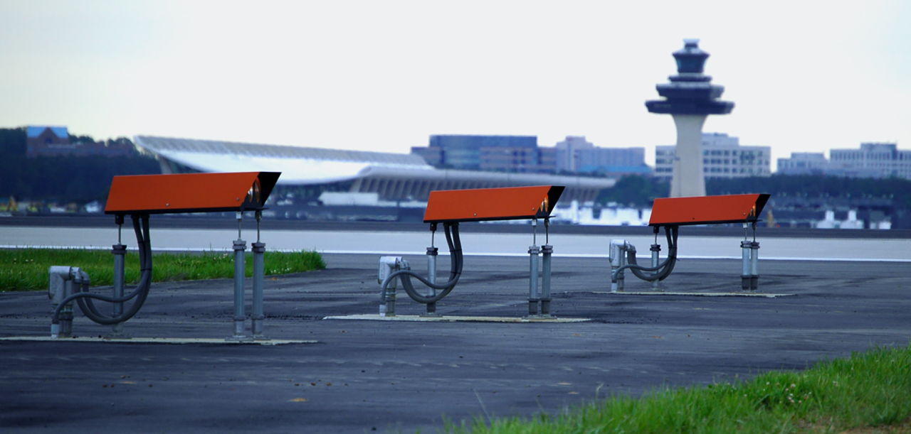
PAPI: Red and White Visual Indications
Precision Approach Path Indicator (PAPI) is a visual approach-slope indicator system. Its lights provide red and white indications according to the aircraft's position relative to the selected visual glide path.
The pattern of red and white indications — not the colour of a single unit viewed in isolation — provides the visual information.
PAPI should therefore be understood separately from fixed runway edge or taxiway lighting colour codes. Its installation, aiming, photometric performance and acceptance checks follow the requirements applicable to the selected system.
A filter over half the beam makes it white above the axis and red below.
AGL Visual Encyclopedia: PAPI optical principle PAPI glide path
ICAO and FAA Colour Requirements: Important Differences
ICAO and FAA provisions share many common colour principles, but specific fixture requirements, installation arrangements and colour-transition distances may differ. A design should use one clearly defined governing basis and include any applicable local requirements.
| Topic | ICAO / Indian airport context | FAA context |
|---|---|---|
| Runway edge lights | Generally white; the approved runway design and aerodrome information define any caution-zone colour arrangement | Applicable instrument runways with specified medium- or high-intensity lighting use yellow in the caution zone, following FAA criteria |
| Runway threshold lights | Green toward the landing approach | Green toward the landing approach |
| Runway-end lights | Red when viewed from within the runway toward the end | Red when viewed from within the runway toward the end |
| Runway centreline lights | A commonly published arrangement uses white, alternating red/white over the next section, and red in the final section | FAA information describes white until 3,000 ft remaining, alternating white/red over the next 2,000 ft, and red over the final 1,000 ft |
| Taxiway edge lights | Blue | Blue |
| Taxiway centreline lights | Green, with applicable runway-exit or runway-proximity transitions | Green, with specified green/yellow lead-on and lead-off arrangements |
| Stop bars | Red where specified | Red where installed |
| Runway guard lights | Yellow in applicable configurations | Yellow, in elevated or in-pavement configurations |
What Should Be Checked Before Applying a Colour Code?
The two systems follow the same idea (white, then alternating red/white, then red) but the transition distances differ.
For ICAO-based projects
Refer to the applicable edition of ICAO Annex 14, Volume I — Aerodrome Design and Operations, including applicable amendments and corrigenda, and the current aerodrome information and approved airport drawings.
For FAA-based projects
Consult the applicable FAA documents, including:
Light Colour, Viewing Direction and Fixture Configuration
A common source of misunderstanding is the assumption that a physical light fitting always displays the same colour from every direction.
Some airfield light fittings are unidirectional, while others are bidirectional or have more complex optical arrangements. A bidirectional fitting may present different colours to aircraft approaching from opposite directions.
For example, a combined threshold/runway-end fitting may display green in the landing approach direction and red in the reciprocal direction.
When interpreting a fixture or drawing, check
- The direction from which the light is intended to be viewed.
- Whether the fitting is unidirectional or bidirectional.
- The intended function of each optical face.
- The exact position of the fixture in the runway or taxiway layout.
- The specified lamp or LED configuration.
- The equipment datasheet and applicable installation requirements.
The same fixture can show different colours to different observers.
AGL Visual Encyclopedia: Beam direction Bidirectional versus unidirectional
Aeronautical Light Colours and Photometry
A light's colour is not defined solely by how it looks in a photograph or on a computer screen. Aeronautical lighting equipment must meet the applicable chromaticity and photometric requirements. Photometric assessment may include checks relating to intensity distribution, beam characteristics and colour characteristics, depending on the equipment and test procedure. When assessing an AGL fixture, distinguish between:
Chromaticity
The defined colour characteristics of the emitted light.
Photometric performance
The intensity and distribution of light in the required directions.
Fixture configuration
The optical arrangement and colour output required for the intended application.
Installation compliance
Whether the installed equipment, orientation and location conform to the approved design.
A light may appear to have the expected colour but still require further checks against its specified photometric or installation requirements.
For product-level requirements, refer to the applicable equipment specification and manufacturer documentation. For design-level requirements, refer to the governing aerodrome standards and approved drawings.
Colour is defined by chromaticity regions, not by how it looks.
AGL Visual Encyclopedia: Chromaticity Colour measurement
AGL Light Colours Are Not Electrical Wiring Colours
The colour of the light emitted by a fixture must not be confused with the identification conventions used for cables, wiring, circuit diagrams or control-system indicators.
For example, a green runway-threshold light does not imply that its associated circuit must use a green cable. Electrical wiring and cable identification must follow the applicable project specification, electrical requirements, approved drawings and manufacturer instructions.
Likewise, a red alarm indicator on a CCR or ALCMS is a control-system status indication. It is not the same thing as a red runway light.
Keep These Categories Separate
| Colour reference | What it describes |
|---|---|
| Aeronautical light colour | The light emitted by a fixture for a defined operational function |
| Electrical cable identification | The identification convention defined by the applicable electrical and project requirements |
| Drawing colour or symbol | The representation specified by the drawing legend |
| Equipment status indication | A display, lamp or alarm defined by the equipment manufacturer and approved control configuration |
Cable tags and route markers identify circuits, not light colours.
AGL Visual Encyclopedia: Cable identification
AGL Colour Code Verification Checklist
Use this checklist as an initial design-review or documentation-review aid.
Design and Documentation
Installation and Inspection
Common Mistakes When Interpreting AGL Colours
Treating every runway edge light as white in every section.
Applicable caution zones may use yellow or amber under the governing requirements.
Applying FAA distances to every ICAO-based runway.
Runway colour transitions must be checked against the specific design and authority.
Assuming that every centreline light is white.
Specified portions of runway centreline systems may use alternating red/white or red arrangements.
Confusing runway threshold lights with runway-end lights.
Their functions and intended viewing directions differ.
Assuming every taxiway centreline remains green.
Selected runway-exit and runway-proximity arrangements may use green and yellow.
Treating stop bars and runway guard lights as the same system.
Stop bars are red; runway guard lights are yellow in applicable configurations.
Assuming all approach lighting systems have the same colours.
The specified system and runway requirements determine which components are installed.
Confusing physical light colours with electrical wiring colours.
Cable and conductor identification follows separate requirements.
Judging compliance from an image alone.
A photograph cannot establish all chromaticity, photometric, installation or acceptance requirements.
Explore the AGL Engineering Knowledge Hub
Fundamentals
Standards & Compliance
Runway, Taxiway & Approach Lighting
Surface Movement & Safety
PAPI
Electrical Engineering & Power
Photometry & Testing
Maintenance, Inspection & Safety
Resources, Documentation & Careers
Frequently Asked Questions
Q1What is the runway lights colour code?
Runway edge lights are generally white, threshold lights show green toward the landing approach, and runway-end lights show red when viewed from within the runway. Runway centreline lights may transition from white to alternating red/white and then red in specified configurations.
Q2Why are taxiway edge lights blue?
Blue taxiway edge lights help identify the boundaries of taxiways. They serve a different function from white runway edge lights.
Q3Why are taxiway centreline lights green?
Green taxiway centreline lights provide guidance along the designated taxiway centreline. Selected runway-exit or runway-proximity arrangements may use alternating green and yellow under the applicable design.
Q4What do red stop bar lights mean?
Red stop bar lights identify a designated holding restriction. Their operation is safety-critical and must be interpreted according to the airport's approved procedures.
Q5What colour are runway guard lights?
Runway guard lights are yellow. Depending on the system, they may use elevated flashing yellow lights or in-pavement yellow lights.
Q6Do runway centreline lights change colour near the runway end?
Yes, where the applicable runway configuration uses colour-transition lighting. Common ICAO/Indian AIP examples use white, alternating red/white, and red in the final sections. FAA guidance uses different transition distances, so the applicable standard must be checked.
Q7Are ICAO and FAA airfield lighting colours identical?
Many basic colour functions are similar, but some fixture arrangements, transition distances and detailed requirements differ. Always verify the applicable standard, airport information and approved design.
Q8Are approach lights always white?
Many approach lighting systems use white lights, but selected configurations include red components. The exact system and its approved layout determine the colour arrangement.
Q9Does a green AGL light mean that its cable must be green?
No. Aeronautical light colours and electrical cable identification are separate systems. Cable and wiring colours must follow the relevant electrical requirements and project documents.
Q10Can AGL colour compliance be confirmed visually?
Visual observation can support an inspection, but it does not by itself establish full compliance. The required assessment may also involve equipment records, approved drawings, specified tests and relevant chromaticity or photometric criteria.
Q11What is the runway lights color code?
The runway lights color code is simple at its core. Runway edge lights are generally white, with amber on part of an instrument runway. Threshold lights are green and runway end lights are red. Centreline lights are white, changing to alternating red and white and then red toward the runway end. Exact zones and chromaticity limits come from ICAO Annex 14, the FAA advisory circulars and the airport's own specification.
Q12What are the runway lighting color code, runway edge lights color code, runway centreline lights color code and threshold lights color code?
As a quick reference, the runway edge lights color code is white (amber in the caution zone of an instrument runway), the runway centreline lights color code is white then red-and-white then red, and the threshold lights color code is green, seen by an approaching pilot. Runway end lights show red when viewed from within the runway. Always confirm the layout and zones against the approved design.
Q13What are the taxiway light colors and the taxiway lighting color code?
The taxiway lighting color code uses blue for taxiway edge lights and green for taxiway centreline lights. Red marks stop bars, and yellow is used for clearance bars and runway guard lights. These taxiway light colors differ from runway colours so pilots can tell taxiways from runways at a glance. Check the airport's approved drawings for the exact lighting types provided.
Q14What is the approach lighting color code?
The approach lighting color code is built mainly on white lights along and across the approach centreline. Depending on the system and category, green threshold lights and red side-row or terminating elements may also appear. The exact arrangement depends on the approach lighting system installed (for example a CAT I or CAT II/III configuration) and on the standard it follows.
Q15What does airport lighting color coding mean?
Airport lighting color coding gives pilots instant visual information. White commonly indicates runway guidance, green the threshold or taxiway centreline, red the runway end or a stop position, blue the taxiway edge and yellow caution or holding-related information. Airport lighting color coding works together with light position, spacing, direction and flashing pattern, not on its own.
Q16What are the airfield lighting color requirements?
Airfield lighting color requirements are set by ICAO Annex 14, the FAA advisory circulars (such as AC 150/5340-30 and AC 150/5345) and national rules such as DGCA requirements in India. They define the colour of each light type and its chromaticity limits, and the airport specification and equipment approvals confirm what is installed. A light that merely looks the right colour has not been proven compliant.
Q17What are the airfield ground lighting color code, airfield lighting color code and airport lighting color code?
The airfield ground lighting color code is the set of colours assigned to each type of light: white, green, red, blue and yellow, with amber used in specific zones. The terms airfield lighting color code and airport lighting color code are used interchangeably for the same system. Use the colour tables above and the relevant standard for the exact assignment of each light.
Q18Is the AGL series circuit color code the same as the light colours?
No. There is no AGL series circuit color code that matches the visible light colours. A series circuit is an electrical loop fed by a constant current regulator, and its cables and connections are identified by the project's cable schedules, labels and standards. Light colour is a photometric property of the fixture, not a wiring code.
Q19Is there a constant current regulator color code?
There is no standard constant current regulator color code for the light colours. CCR terminals, output leads and brightness steps are identified by manufacturer markings, drawings and labels. Do not infer a CCR's function from the colour of the lights it feeds, and always use the approved drawings and the manufacturer's manual.
Q20Is there an airfield lighting isolation transformer color code or airfield lighting cable color code?
The airfield lighting isolation transformer color code and airfield lighting cable color code refer to wiring identification, not the colour the pilot sees. Primary and secondary leads and cores are identified by markings, labels, drawings and the applicable electrical standard. Always follow the approved project documents rather than assuming a colour convention.
Q21Is there an airfield lighting control system color code or ALCMS color code?
An airfield lighting control system color code, or ALCMS color code, usually means the status colours on the operator screen or mimic. These are defined by the project's HMI and alarm philosophy, not by a universal rule, so one airport's red or amber state may not match another's. Check the airport's control system documentation and operator procedures.
Use This Page as a Learning Reference
Airfield lighting colour codes provide important visual information, but their correct interpretation depends on the lighting function, viewing direction, system configuration and governing requirements.
Use this page as a learning reference. For design, installation, inspection, testing and maintenance, follow the applicable standards, current aerodrome information, approved airport drawings and authorized procedures.
Technical References
Specification for Runway, Taxiway, Heliport, and Vertiport Light Fixtures
Engineering & Expert Notes
Colour Alone Does Not Define the Meaning
PrincipleThe meaning of a light depends on its colour together with position, pattern, intensity and direction. Teach and check all of these, not the colour in isolation.
Check Colour From the Pilot's Viewing Direction
ViewingA light can read correctly from one approach and show a different colour or none from the opposite side. Verify from the direction the intended user will see it.
LED Colour Can Shift With Age, Temperature and Dimming
LEDChromaticity should be verified against the specified limits during commissioning and periodic checks, not assumed to stay constant for the life of the fixture.
Replacement Filters and Lenses Must Match the Fixture Approval
SparesUsing a generic coloured lens or filter can alter both colour and intensity. Replace with the approved part for that fixture type and record the change.
Fading and Contamination Create Subtle Misreads
MaintenanceDiscoloured lenses and dirt on optics can make a light appear less saturated or dimmer. Include cleaning and visual colour checks in night inspections.
Record Colour Checks Like Any Other Test
RecordsNote the method, instrument and result for colour verification so later changes in a fixture's output can be compared with the baseline instead of judged by eye.
Understand AGL. Build Your Engineering Skills.
You now know how AGL colour codes work — and why colour must always be read together with function, viewing direction and the governing standard.
Take the next step with Precision AGL Academy.
Follow the Academy
Important Notice, Disclaimer & Limitation of Liability
Please read before relying on any content on this page or on any record downloaded from it.
- Purpose and intended users. This page is an independent educational and informational reference for competent, suitably trained and authorised airfield ground lighting (AGL) and aerodrome personnel. It is not professional engineering, legal or regulatory advice, and using it creates no professional or client relationship. Learning-path and Academy references describe stages of learning only and are not a certification, accreditation or authorisation.
- Safety. Work on series circuits, constant current regulators (CCRs), isolating transformers, cables, connectors and lighting fixtures can be fatal. Always apply the aerodrome’s permit-to-work and isolation/LOTO procedures, prove dead, use correctly rated instruments and PPE, and follow the manufacturer’s instructions. Nothing here authorises work on live equipment or the bypassing of any safety device or interlock.
- Aviation operations. Nothing on this page authorises return to service, the installation, adjustment or modification of any aviation visual aid, a change of operating category (CAT I/II/III), a NOTAM or any aerodrome certification decision. These rest with the aerodrome operator, the air navigation service provider and the competent regulator.
- Standards, regulations and named sources. References to ICAO, FAA, EASA, DGCA, AAI, IEC, IEEE, ISO, BIS and other standards, regulations, AIP material and published sources, and statements about what a named airport, State or authority has published, are summaries for orientation as understood when the page was prepared. They are not official text, may be incomplete, amended or superseded, and have not been independently verified. Consult the current official editions, including the current AIP, AIRAC cycle and NOTAMs. Following this content does not guarantee compliance with any law, standard or approval, and official documents, regulations, the approved design and manufacturers’ instructions always prevail.
- Generic content; no warranty. Values, tolerances, intervals, sequences, examples, checklists and pass/fail or “compliant” wording are generic and indicative; real installations differ in design, make, model, age and condition. Content is provided “as is” and “as available”, without warranty of any kind, express or implied, including accuracy, completeness, currency or fitness for a particular purpose.
- Images, diagrams and credits. Photographs on this page carry a credit line in their caption naming the source and, where stated, the licence (for example U.S. Government public-domain works or openly licensed images). They illustrate a type of equipment or situation, may not show the exact item described, imply no endorsement by or affiliation with any person, organisation or manufacturer shown, and remain subject to their owners’ rights. Diagrams are original schematic illustrations, are not to scale and are not engineering drawings. To request a correction, credit or removal, write to the contact address below.
- Limitation of liability. To the fullest extent permitted by applicable law, Precision AGL Academy and its owners, authors and contributors are not liable for any injury, death, loss, damage, downtime, penalty or regulatory consequence, whether direct or indirect, arising from the use of, reliance on, or inability to use this content. Nothing in this notice excludes or limits any liability that cannot lawfully be excluded or limited.
- Independence and trademarks. This is an independent publication, not affiliated with or endorsed by ICAO, the FAA, EASA, the IEC, DGCA, AAI, any airport, regulator, employer or equipment manufacturer. Third-party names, standard designations and trademarks (including Megger®) belong to their respective owners and are used for identification only.
- Copyright and use. © 2026 Precision AGL Academy. All rights reserved. The text, structure, diagrams and compilation of this page are protected by copyright. You may read it and use it for personal reference and internal training, keeping this notice attached; any other copying, republication, scraping or commercial use needs our prior written permission. Credited third-party photographs remain subject to their owners’ terms.
- Corrections. Content is reviewed periodically, with no obligation to update. To report an error, safety concern, copyright, privacy or other rights issue, write to precisionaglsolutions@gmail.com.